Northern Industrial Tools 998253 User manual

4.1 CU. FT. MIXER
OWNER’S MANUAL
WARNING:
Read carefully and understand all INSTRUCTIONS before
operating. Failure to follow the safety rules and other basic
safety precautions may result in serious personal injury.
Item #998253

Thank you very much for choosing a NORTHERN MIXER + EQUIPMENT CO., INC. Product!
For future reference, please complete the owner’s record below:
Model: _______________ Purchase Date: _______________
Save the receipt, warranty and these instructions. It is important that you read the entire manual
to become familiar with this product before you begin using it.
This machine is designed for certain applications only. Northern Mixer + Equipment strongly
recommends this machine is not modified and/or used for any application other than that for
which it was designed. If you have any questions relative to a particular application, DO NOT
use the machine until you have first contacted Northern Mixer + Equipment to determine if it can
or should be performed on the product.
For technical questions and replacement parts, please call 1-800-222-5381.
INTENDED USE
The Cement Mixer is designed for mixing cement. This particular model is small, efficient, easy to
assemble and transport, making it ideal for both home and jobsite use.
TECHNICAL SPECIFICATIONS
Item Description
Drum Capacity 4.1 Cubic Feet
Drum Opening 17"
Drum speed 30 RPM
Motor
Input Power: 1/2 HP;
Output Power: 1/3 HP
RPM: 1720
Voltage: 120 VAC at 60 Hz,
Overall Dimensions 45.5"(L) x 28"(W) x 55"(H)
Net Weight 132 Lbs.
GENERAL SAFETY RULES
WARNING: Read and understand all instructions. Failure to follow all instructions listed
below may result in electric shock, fire and/or serious injury.
WARNING: The warnings, cautions, and instructions discussed in this instruction
manual cannot cover all possible conditions or situations that could occur. It must be
understood by the operator that common sense and caution are factors which cannot be built into
this product, but must be supplied by the operator.
Page of 132

Page of 13
3
SAVE THESE INSTRUCTIONS
WORK AREA
Keep work area clean, free of clutter and well lit. Cluttered and dark work areas can cause
accidents.
Do not use your mixer where there is a risk of causing a fire or an explosion; e.g. in the
presence of flammable liquids, gasses, or dust. Electric motors may create sparks, which may
ignite the dust or fumes.
Keep children and bystanders away while operating a mixer. Distractions can cause you to
lose control, so visitors should remain at a safe distance from the work area.
Be aware of all power lines, electrical circuits, water pipes and other mechanical hazards in
your work area, particularly those hazards below the work surface hidden from the operator’s
view that may be unintentionally contacted and may cause personal harm or property damage.
Be alert of your surroundings. Using mixers in confined work areas may put you dangerously
close to cutting mixers and rotating parts.
ELECTRICAL SAFETY
WARNING! Always check to ensure the power supply corresponds to the voltage on
the rating plate.
Do not abuse the cord. Never carry or pull a mixer by its power cord, or yank power cords or
extension cords from the receptacle. Keep power and extension cords away from heat, oil,
sharp edges or moving parts. Replace damaged cords immediately. Damaged cords may cause
a fire and increase the risk of electric shock.
Grounded motors must be plugged into an outlet properly installed and grounded in
accordance with all codes and ordinances.Never remove the grounding prong or modify the
plug in any way. Do not use any adapter plugs. Check with a qualified electrician if you are in
doubt as to whether the outlet is properly grounded.
Double insulated electrical motors are equipped with a polarized plug (one blade is wider
than the other). This plug will fit in a polarized outlet only one way. If the plug does not fit fully in
the outlet, reverse the plug. If it still doesn’t fit, contact a qualified electrician to install a polarized
outlet. Do not change the plug in any way.
Avoid body contact with grounded surfaces such as pipes, radiators, ranges, and refrigerators.
There is an increase risk of electric shock if your body is grounded.
When operating a electric mixer outside, use an outdoor extension cord marked “W-A” or
“W.” These cords are rated for outdoor use and reduce the risk of electric shock.
Extension Cord Use.
A. Use only ‘Listed’ extension cords. If used outdoors, they must be marked “For Outdoor
Use.” Those cords having 3-prong grounding type plugs and mating receptacles are to be
used with grounded mixers.
B. Replace damaged or worn cords immediately.
C. Check the name plate rating of your mixer. Use of improper size or gauge of extension cord
may cause unsafe or inefficient operation of your mixer. Be sure your extension cord is
rated to allow sufficient current flow to the motor. For the proper wire gauge for your mixer,

Page of 13
4
see chart.
CHART FOR MINIMUM WIRE SIZE OF EXTENSION CORD:
Nameplate AMPS
CORD LENGTH
25'
50'
100'
150'
0-6
18 AWG
16 AWG
16 AWG
14 AWG
6-10
18 AWG
16 AWG
14 AWG
12 AWG
10-12
16 AWG
16 AWG
14 AWG
12 AWG
12-16
14 AWG
12 AWG
(NOT RECOMMENDED)
If in doubt, use larger cord.
Be sure to check voltage requirements of the mixer to your incoming power source.
Do not expose mixers to rain or wet conditions. Water entering a motor compartment will
increase the risk of electric shock.
Do not let your fingers touch the terminals of plug when installing to or removing from the
outlet.
Ground fault circuit interrupters. If work area is not equipped with a permanently installed
Ground Fault Circuit Interrupter outlet (GFCI), use a plug-in GFCI between mixer or extension
cord and power receptacle.
PERSONAL SAFETY
Stay alert, watch what you are doing and use common sense when operating a mixer. Do not
use a mixer while you are tired or under the influence of drugs, alcohol or medication. A moment
of inattention while operating mixers may result in serious personal injury.
Dress properly. Do not wear loose clothing, dangling objects, or jewelry. Keep your hair,
clothing and gloves away from moving parts. Loose clothes, jewelry or long hair can be caught
in moving parts. Air vents often cover moving parts and should be avoided.
Use safety apparel and equipment. Use safety goggles or safety glasses with side shields
which comply with current national standards, or when needed, a face shield. Use as dust mask
in dusty work conditions. This applies to all persons in the work area. Also use non-skid safety
shoes, hardhat, gloves, dust collection systems, and hearing protection when appropriate.
Avoid accidental starting. Ensure the switch is in the off position before plugging mixer into
power outlet. In the event of a power failure, while a mixer is being used, turn the switch off to
prevent surprise starting when power is restored.
Do not overreach. Keep proper footing and balance at all times.
Remove adjusting keys or wrenches before connecting to the power supply or turning on the
mixer. A wrench or key that is left attached to a rotating part of the mixer may result in personal
injury.
MIXER USE AND CARE
Do not force the mixer to perform an operation other than its intended use. Mixers do a
better and safer job when used in the manner for which they are designed. Plan your work, and
use the correct mixer for the job.
Never use a mixer with a malfunctioning switch. Any mixer that cannot be controlled with the
switch is dangerous and must be repaired by an authorized service representative before using.
Disconnect the power from mixer and place the switch in the locked or off position before
servicing, adjusting, installing accessories or attachments, or storing. Such preventive safety
measures reduce the risk of starting the mixer accidentally.

Page of 13
5
Store idle mixers. When mixers are not is use, store them in a dry, secure place out of the
reach of children. Inspect mixers for good working condition prior to storage and before re-use.
Maintain your mixers. It is recommended that the general condition of any mixer be examined
before it is used. Keep your mixers in good repair by adopting a program of conscientious repair
and maintenance in accordance with the recommended procedures found in this manual. If any
abnormal vibrations or noise occurs, turn the mixer off immediately and have the problem
corrected before further use. Have necessary repairs made by qualified service personnel.
Keep mixer blades clean. Properly maintained mixing blades are less likely to fail and will
perform the job required. Keep handles dry, clean, and free from oil and grease.
Cleaning and Lubrication. Use only soap and a damp cloth to clean your mixers. Many
household cleaners are harmful to plastics and other insulation. Never let liquid get inside the
motor compartment.
Use only accessories that are recommended by the manufacturer for your model.
Accessories that may be suitable for one mixer may create a risk of injury when used on
another mixer.
Keep guards in place and in working order.
Never leave mixer running unattended.
ASSEMBLY
1. Place Stand (1) into Hinge Bracket (2) so that bolt holes line up as shown in photo below (also
see Assembly Drawing on last page).
2. Insert Hex Bolts (3) through holes from one side, then Flat Washer (4), Spring Washer (7) and
Hex Nut (5) from the other side, and tighten with a wrench.
3. Insert Support Bracket (6) onto Stand (1) so that bolt holes line up.
4. Insert Hex Bolts (3) through holes from one side, then Flat Washer (4), Spring Washer (7) and
Hex Nut (5) from the other side, and tighten with a wrench.
5. Place Stand upright as shown in the photo below.
6. Place Flat Washer (11) onto Hinge Bracket axle, then the Wheel (10), and another Flat Washer
(11).
7. Insert (split) Pins (12) into the Hinge Bracket (2) axle holes, outside each Flat Washer. That is,
each Flat Washer should be touching the wheel, not the pin.

Page of 13
6
8. Bend each side of the Pins outward so they do not fall out.
9. With two people, set the Lower Drum (17) with attached Support Arm (13) assembly into Stand
assembly. See photo below.
10. Insert Hex Bolts (8) through holes from one side, then Flat Washer (4), Spring Washer (7) and
Hex Nut (5) from the other side, and tighten with a wrench.
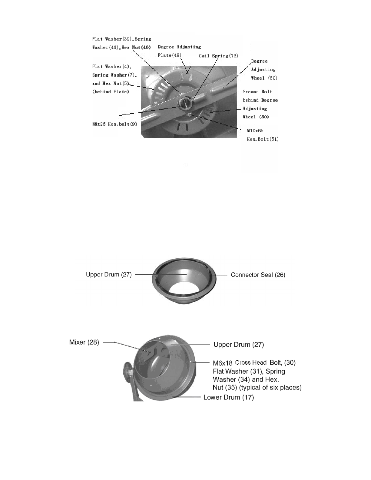
11. Mount Degree Adjusting Plate (49) to Iron Tube Fixture(R.H.) (38) using two M8x25 Hex. Bolts
(9) from the outside. Secure from the inside with a Flat Washer (4), Spring Washer (7), then Hex.
Nut (5).
Page of 13
7
12. Attach Degree Adjusting Wheel (50) to Iron Tube - R.H. (15) shaft as shown above.
a.) Insert Coil Spring (73) into lower hole of Degree Adjusting Wheel (50).
b.) Press down on Arm until holes align on the Iron Tube -R.H.(15).
c.) Insert the M10x65 Hex. Bolt (51) and on the other side secure with Flat Washer (39), Spring
Washer (41) and Hex. Nut (40).
d.) Tighten to a point where the Arm can still move.
13. Glue the Connector Seal (26) to the Upper Drum (27), making sure that the holes in both align.
The Connector Seal must be flat on the Upper Drum to ensure a proper seal.
14. Place the Upper Drum (27) on the Lower Drum (17), making sure the mounting holes align in
both.
15. Insert the six M6x18 Cross Head Bolts (30) with six Flat Washer(31) into each mounting hole.
Under the Drum, secure each Bolt with a Spring Washer (34) and Hex. Nut (35).
16. Mount each Mixer (28) inside the assembled drum with the pointed end facing downward
(See photo at bottom of previous page). Also, the V-shaped bend in the Mixers should

Page of 13
8
pointed in the direction of the Drum rotation (clockwise). When correct Mixer (28) position is
found, go ahead to fix it. First, put one M8x25 Cross Head Bolt (32) from outside of the drum
upper (or lower), and insert one Leather Washer (29) to the Bolt (32) from inside of the Drum.
Then, put the Mixer (28) next to the Leather Washer (29) . Finally, put Flat Washer (4) ,Spring
Washer (7) to the Bolt (32) and fix with the Hex Nut (5). To repeat this procedure, and fix the
other 3 Bolts.
17. Mount the inner Motor Base Cover (58) to the Iron Tube Fixture (L.H.) (37) bearing using two
M8x25 Hex Bolts (9), Flat Washer (4), Spring washers (7) and Hex Nuts (5).
18. Attach the Motor Mount Plate (55) to the inner Motor Base Cover (58) using the Hex. Bolt (46),
Flat Washer (31), Spring Washer (34), Hex. Nut (35), and Strap (61). Tighten sufficiently to hold
in place. See photo above.
Note: Once the Motor (52) is mounted, the Motor Mount Plate must be adjusted up or down to
tighten the Belt (68).
19. Place the Motor (52), attached by power cable to the outer Motor Base Cover (64), on top of the
Motor Mount Plate (55). Refer to the photo on the top of the next page.
20. Secure the Motor to the Motor Mount Plate using M8x20 Hex. Bolt (56), Flat Washer (4), Spring
Washer (7) and Hex. Nut (5). Tighten all four Hex. Nuts hand-tight. The Motor will be adjusted
forward or backward later.
21. Clean the pinion shaft of all plastic protective material and other debris. Also clean out debris
from Pulley (45) center hole.
22. Squarely push the Pulley center onto the pinion shaft so that the groove in the pulley engages
the Key (53). The Pulley should be flush with the step on the pinion shaft.
Cautio n: Do not pound the Pulley onto the pinion shaft. Damage can occur causing a loose fit.

Page of 13
9
23. Once the Pulley is pushed in all the way, use an Allen wrench to tighten the Set Screw (70) on
the side of the Pulley hub.
24. Install the pulley Belt (68). Place Belt around Motor drive Pulley (54), then over the belt Pulley
(45). Push the Motor inward until the drive pulley is directly under the belt Pulley. Tighten the four
Bolts securing the Motor to the Motor Mount Plate.
25. Push the Motor downward until the Belt tension is tight. This step may require tapping down the
Strap (61) behind the Inner Motor Base Cover (58). Refer to the photo at the top of the previous
page. When proper tension is achieved, tighten the Hex. Nuts on the Strap (61).
26. Check if Motor and belt turns true. Hand turn the belt Pulley and verify that the Motor drive
pulley and belt pulley does not rub against any other part, and that the pulleys turn true. Make
adjustments to Motor location as required.
27. Mount the Outer Motor Base Cover (64) to the Inner Motor Base Cover (58) using three M5x10
Screws (65), Flat Washer (59), Spring Washers (66) and Hex Nuts (67). Make sure that the
power cord from the Motor to the Switch (71) does not come in contact with moving parts.
28. The Cement Mixer assembly is complete. Go back and retighten all screws, nuts, and bolts.
OPERATION
1. Place the Cement Mixer on a solid, even surface.
2. Connect the Power Cord (72) to an electrical outlet (or properly rated extension cord) with a
third, ground prong.
3. Add material to the Drum. Typical maximum quantities include: 2 gallons water, 3 shovels
cement, 15 shovels aggregate rock using a size 3 shovel.
Warning: Do not attempt to move the Cement Mixer when it is full and/or in operation. Injury to
personnel could occur.
4. Adjust the Drum angle by pulling out on the Degree Adjusting Arm (50), disengaging the locking
pins, and push on Arm until the desired angle is reached. Reengage the locking pins.
5. Flip the Switch (71) to the (I) or On position.

Page of 13
10
6. Filling and emptying the Drum is best done with the Drum rotating.
Warni ng: Never leave the Cement Mixer running while unattended. Do not turn Mixer Off while full
of cement.
7. When finished, flip the Switch to the (O) or Off position, and disconnect the Power Cord.
8. Turn the Drum angle as far down as possible to drain all fluids from Drum.
MAINTENANCE
1. After use, immediately wash out all debris from the inside and outside of the Cement Mixer.
Make sure the Power Cord is disconnected.
2. Do not apply water in or around the Motor Base Cover.
3. Retighten belt after the first 25 hours of use. The belt should be able to be pressed in no more
that 1/4".
4. Periodically recheck all nuts, bolts, and screws for tightness.
Switch Assembly (71)
Motor Base Cover
Page of 13
11
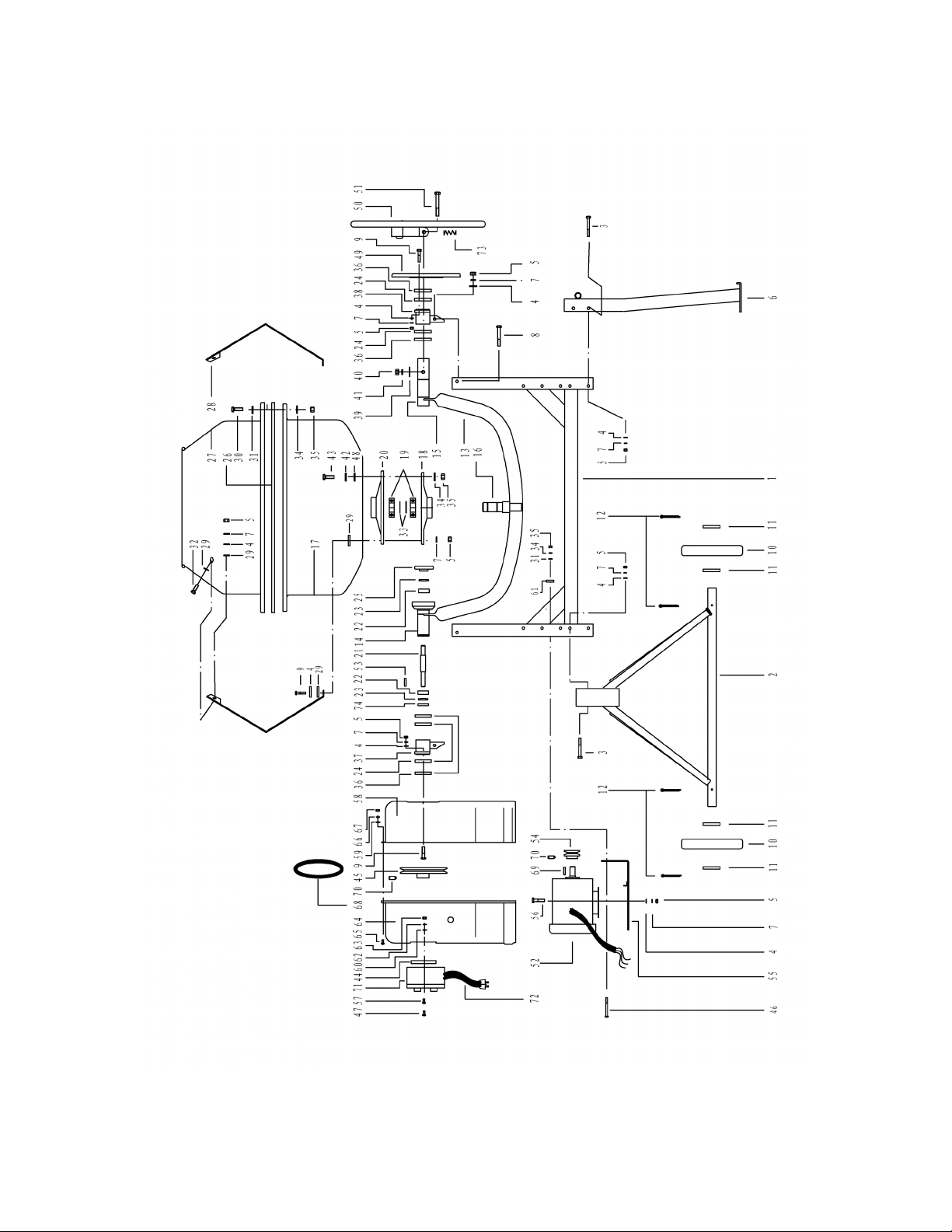
DIAGRAM & PARTS LIST

Page of 13
12
Item
Description
Qty
Item
Description
Qty
1
Stand
1
38
Iron Tube Fixture (R.H.)
1
2
Hinge Bracket
1
39
Flat Washer 10
1
3
Hex. Bolt M8x70
4
40
Hex. Nut M10
1
4
Flat Washer 8
20
41
Spring Washer 10
1
5
Hex. Nut M8
20
42
Flat Washer 6
8
6
Support Bracket
1
43
Hex Bolt M6x20
8
7
Spring Washer 8
20
44
Switch Mount Plate
1
8
Hex. Bolt M8x65
2
45
Pulley (L)
1
9
Hex. Bolt M8x25
6
46
Hex. Bolt M6x65
2
10
Wheel
2
47
Screw M4x12
4
11
Flat Washer
4
48
Leather Washer 6
8
12
Pin 5x40
4
49
Degree Adjusting Plate
1
13
Support Arm
1
50
Degree Adjusting Wheel
1
14
Iron Tube (L.H.)
1
51
Hex. Bolt M10x65
1
15
Iron Tube (R.H.)
1
52
Motor
1
16
Shaft Assembly
1
53
Key 5x35
1
17
Drum, Lower
1
54
Pulley(s)
1
18
Washer Cover, Lower
1
55
Motor Mount Plate
1
19
Ball Bearing 6206-2RS
2
56
Hex. Bolt M8x20
4
20
Washer Cover, Upper
1
57
Screw M4x16
2
21
Shaft
1
58
Motor Base Cover, Inner
1
22
Ball Bearing 6002-2RS
2
59
Flat Washer 5
3
23
Bearing Shell
2
60
Flat Washer 4
6
24
Adjusting Flat Washer
4
61
Strap
1
25
Gear
1
62
Spring Washer 4
4
26
Connector Seal
1
63
Hex. Nut M4
6
27
Drum, Upper
1
64
Motor Base Cover, Outer
1
28
Mixer
2
65
Screw M5x10
3
29
Leather Washer 7
4
66
Spring Washer 5
3
30
Cross Head Bolt M6x18
6
67
Hex. Nut M5
3
31
Flat Washer 6
8
68
Belt
1
32
Cross Head Bolt M8x25
4
69
Key 5x30
1
33
C-clip 30
2
70
Set Screw M5x30
2
34
Spring Washer 6
8
71
Switch Assembly
1
35
Hex. Nut M6
8
72
Power Cord
1
36
C-clip 38
4
73
Coil Spring
1
37
Iron Tube Fixture (L.H.)
1
74
C-clip 15
1

Page of 13
13
WARNING
Some dust created by power sanding, sawing, grinding, drilling, and other construction activities contains
chemicals known to the State of California to cause cancer, birth defects or other reproductive harm.
Some examples of these chemicals are:
• lead from lead-based paints,
• crystalline silica from bricks and cement and other masonry products, and
• arsenic and chromium from chemically-treated lumber.
Your risk from these exposures varies, depending on how often you do this type of work. To reduce your
exposure to these chemicals: work in a well ventilated area, and work with approved safety equipment,
such as those dust masks that are specially designed to filter out microscopic particles.
Northern Mixer + Equipment Co.,
2800 Southcross Drive West
P.O. Box 1499 Burnsville, MN 55337-0499
Made in China.
Table of contents
Other Northern Industrial Tools Mixer manuals


