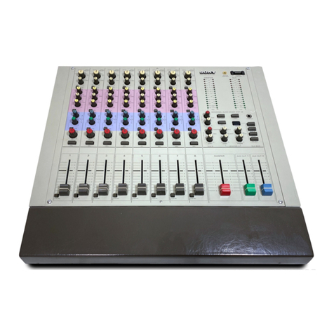
Sony SRP-V200 User manual

1
Table of Contents
Warning
Notice for the Customers in the United Kingdom
IMPORTANT
The wires in this mains lead are coloured in accordance with the
following code:
Blue:Neutral
Brown:Live
As the colours of the wires in the mains lead of this apparatus may
not correspond with the coloured markings identifying the terminals
in your plug, proceed as follows:
The wire which is coloured blue must be connected to the terminal
which is marked with the letter N or coloured black. The wire which
is coloured brown must be connected to the terminal which is
marked with the letter L or coloured red. Do not connect either wire
to the earth terminal in the plug which is marked by the letter E or
by the safety earth symbol Y or coloured green or green-and-yellow.
AUDIO MIXER
SRP-V200
Operating instructions
Beforeoperatingtheunit,pleasereadthismanualandthesupplied“WARNING”
thoroughly and retain it for future reference.
Precautions
On safety (Refer to the supplied “WARNING”.)
• Should any liquid or solid object fall into the cabinet, unplug the unit and
have it checked by qualified personnel before operating it any further.
•Unplug the unit from the wall outlet if it is not to be used for an extended
period of time. To disconnect the cord, pull it out by grasping the plug.
Never pull the cord itself.
On installation
• Do not install the unit in a location near heat sources such as radiators or
air ducts, or in a place subject to direct sunlight, excessive dust, mechanical
vibration or shock.
On operation
• Before making program source connections, be sure to turn the power
switch off and unplug the unit.
• When the unit is not used, turn the power off to conserve energy and to
extend the useful life of your unit.
On cleaning the cabinet
Clean the cabinet, panel and controls with a soft cloth lightly moistened with
mild detergent solution. Do not use any type of abrasive pad, scouring powder
or solvent such as alcohol or benzine.
On repacking
Do not throw away the carton and the packing material. It makes an ideal
container for transporting the unit.
When shipping the unit for repair work or to another location, repack it as it
was.
If you have any questions or problems concerning your unit, please contact
your nearest Sony dealer.
©1999 by Sony Sound Tec Corporation
2-346-938-11 (2)
Warning............................................. 2
Main characteristics......................... 3
Dimensions....................................... 3
System Configuration ...................... 14
Video Editor Connection ................. 18
Block diagram................................... 24
Main specifications .......................... 25
Name and function of each parts.... 4
MONO INPUT section......................... 4
STEREO INPUT section ..................... 6
MONITOR section............................... 8
MASTER section ................................ 10
INTERFACE section ........................... 11
BACK PANEL...................................... 12

2
Nederlands
WAARSCHUWING
Stel het apparaat niet bloot aan regen of vocht, om
gevaar van brand of een elektrische schok te
voorkomen.
Open niet de behuizing, om gevaar van elektrische
shokken te vermijden. Laat reparatiles aan de erkende
vakhandel over.
Português
ADVERTÊNCIA
Para evitar o risco de incêndio ou de choques
eléctricos, não exponha o aparelho à chuva nem à
humidade.
Para evitar descargas eléctricas, não abra o aparelho.
Peça assistência somente a técnicos especializados.
Dansk
ADVARSEL
For at undgå faren for brand eller elektrisk stød må
udstyret ikke udsættes for regn eller kraftig fugt.
Åbn ikke kabinettet, da der er risiko for elektriske stød.
Overlad alle reparationer til kvalificeret
servicepersonale.
Suomi
VAROITUS
Tulipalon ja iskuvaaran välttämiseksi ei laitetta saa
altistaa sateelle ja kosteudelle.
Sähköiskun välttämiseksi ei koteloa saa avata. Anna
vain asiantuntijan suorittaa huolto.
WARNING
English
WARNING
To prevent fire or shock hazard, do not expose the unit
top rain or moisture.
To avoid electrical shock, do not open the cabinet.
Refer servicing to qualified personnel only.
This unit can be used in a commercial district or a light
industrial area. This unit conforms with the limits for the EN
55022 Class B.
Svenska
VARNING
Utsätt inte apparaten för regn och fukt för att undvika
riskerna för brand och/eller elektriska stötar.
Öppna inte höljet. Det kan resultera i risk för elektriska
stötar. Överlåt allt reparations- och underhållsarbete till
fackkunniga tekniker.
Italiano
ATTENZIONE
Per evitare il pericolo di incendi o scosse elettriche,
l’apparecchio non deve essere esposto alla pioggia o
all’umidià.
Per evitare scosse elettriche, non aprire l’apparecchio.
Per le riparazioni rivolgersi solo a personale qualificato.
Français
AVERTISSEMENT
Afin d’éviter tout risque d’incendie ou d’électrocution,
ne pas exposer l’appareil à la pluie ou à l’humidité.
Afin d’écarter tout risque d’électrocution, garder le
coffret fermé. Ne confier l’entretien de l’appareil qu’à un
personnel qualifié.
Deutsch
VORSICHT
Um die Feuergefahr und die Gefahr eines elektrischen
Schlages zu vermeiden, darf das Gerät weder Regen
noch Feuchtigkeit ausgesetzt werden.
Um einen elektrischen Schlag zu vermeiden, darf das
Gehäuse nicht geöffnet werden. Überlassen Sie
Wartungsarbeiten stets nur einem Fachmann.
Dieses Produkt kann im kommerziellen und in begrenztem
Maße auch im industriellen Bereich eingesetzt werden. Das
Gerät hält die für EN 55022 Klasse B vorgeschriebenen
Grenzwerte ein.
Español
ADVERTENCIA
Para evitar incendios o el riesgo de electrocución, no
exponga la unidad a la lluvia ni a la humedad.
Para evitar descargas eléctricas, no abra la caja. En
caso de avería solicite los servicios de personal
cualificado solamente.
Norsk
ADVARSEL
For å hindre brann og støtfare må enhetens overflate
ikke utsettes for regn eller fuktighet.
For å unngå elektrisk støt må kassen ikke åpnes.
Service må bare utføres av kvalifisert personell.

3
Main characteristics
The SRP-V200 is a compact audio mixer designed for use in
a small or medium-size video edit suite. Mounted in a 19" rack
and controlled from the video editor, the SRP-V200 enables
audio editing in synchronization with video images.
Versatile Inputs/Outputs
The SRP-V200 provides 4 channels of mono inputs and 6
channels of stereo inputs. Outputs include 4 channels of
master, AUX and monitor outputs, plus a PFL output and a TB
output. The mono input channels can accept either line or
microphone level signals. They also feature switchable A and
B inputs in addition to an individual low-cut filter and 3-band
equalizer.
DC +48V Power Supply for Condenser Microphones
The mono input channels incorporate a DC +48V power supply
(phantom powering) for biasing condenser microphones.
Remote Control from Video Editor
Connected to a video system via Sony-standard parallel
interface, the SRP-V200 can be remote controlled from a video
editor. Editor-controllablefunctionsincludecrossfading,preview
monitoring, and recorder (VTR) assignment. Initial settings
necessary for matching the mixer to the video environment are
simple and easy.
Easy Mounting into 19" EIA Standard Rack (8U Size)
MU-200TK Table Kit Optionally Available for Desktop
Installation
Dimensions
Unit : mm
A
A
A
A
A
A
A
A
A
A
A
A
A
A
A
A
A
A
A
A
A
A
A
A
A
A
AA
AA
A
A
A
A
A
A
AA
AA
AA
AA
AA
AA
A
A
AA
AA
A
A
A
A
AA
AA
A
A
A
A
AA
AA
A
A
A
A
1
481
424
355
130 10
337
349
57

4
Name and function of each parts
AA
AA
AA
AA
AA
AA
AA
AA
AA
AA
AA
AA
AA
AA
AA
AA
AA
AA
AA
AA
A
AA
AA
AA
AA
AA
AA
AA
AA
AA
A
A
A
A
AA
A
AA
AA
A
A
AA
AA
AA
AA
A
A
AA
AA
MONO INPUT section
B
HIGH
MID
LOW
PRE
AUX
PAN
LOCAL
PFL
PEAK
AA
MUTING
1
1
3
2
4
3-4
1-2
LEVEL
LCF
LINE
MIC/+48V
MIC
-60
-30
-17
+13
+15
-15
+15
-15
+15
-15
1/3
AUX
2/4
0
-∞
0
-∞
EVEN
ODD
C
10
5
0
20
30
+
-∞
10
5
5
3
2
6
4
1
9
7
8
10
11
12
13
14
15
16
17
18

5
Input-A Level Switch
Controls the signal level at the mono input connector A.
Thethree switchpositionscanbeused asfollows according
to the connected source unit.
LINE:
When connecting a line signal from a CD or MD player.
MIC:
When connecting a microphone.
MIC +48V:
When it is necessary to externally power the connected
microphone.
LEVEL (Input-A Level) Control
Adjusts the level of the signal supplied through the mono
input connector A. The adjustable range is +13 to -30 dBu
when the LEVEL control is set to LINE and -17 to -60 dBu
when it is set to MIC or MIC +48V.
B (Input-B Selector) Button
Press to select the signal supplied through the mono input
connector B instead of the one through A.
LCF (Low-Cut Filter) Button
Activates the low-cut filter to roll off low frequencies below
100 Hz at 12 dB/oct.
HIGH (High Frequency Equalizer) Control
Controls the level of the shelving-type high frequency
equalizer in a range from -15 to +15 dB. The turnover
frequency is 10kHz.
MID (Mid Frequency Equalizer) Control
Controls the level of the peaking-type mid frequency
equalizer in a range from -15 to +15 dB. The center
frequency is 2.5 kHz.
LOW (Low Frequency Equalizer) Control
Controls the level of the peaking-type low frequency
equalizer in a range from -15 to +15 dB. The center
frequency is 60 Hz.
PEAK Indicator
Illuminateswhentheinputsignallevel,afterpassingthrough
the equalizer, has reached 3 dB below the maximum level.
When this LED is lit, the input level is too high, so adjust
using the LEVEL control. If it is impossible to decrease to
an appropriately low level, set the Input-A switch to the
LINE position and adjust again with the LEVEL control.
AUX 1/3 (AUX Output 1/3 Level) Control
Controls the level of the signal to be routed to AUX output
1 or 3. The reference level can be obtained by setting the
control to the "0" (maximum) position.
AUX 2/4 (AUX Output 2/4 Level) Control
Controls the level of the signal to be sent to AUX output 2
or 4. The reference level can be obtained by setting the
control to the "0" (maximum) position.
PRE (Pre-Fader) Button
Used to assign either pre-fader or post-fader signal to the
AUX outputs. The pre-fader signal is the signal before
passing through the channel fader. The post-fader signal
is the one after passing through it. The pre-fader signal is
selected when the PRE button is pressed.
1-2/3-4 (AUX Output Selection) Button
Press this button to send the signal to AUX outputs 3 and
4. Releaseitto sendthe signaltoAUX outputs1 and 2. The
AUX outputs are pre-grouped, making it impossible to send
the signal from one input channel simultaneously to other
combinations such as AUX 1 and 4 or AUX 2 and 3. The
signal level is controlled by the AUX 1/3 or AUX 2/4 control.
PAN (Pan Pot ) Control
To adjust sound definition, this control allows continuous
panning of the input signal between MASTER outputs 1
and 3 (odd channels) and 2 and 4 (even channels). When
rotated to the maximum position marked ODD or EVEN,
the level of the corresponding MASTER output signals is 3
dB higher than at the center position.
1, 2, 3, 4 (MASTER Output Channel Selection)
Buttons
Press to select the MASTER output channel. The signal is
transmitted to the channel corresponding to the pressed
button.
MUTING Button
Press to mute the MASTER output. Unless the PRE button
is pressed, the post-fader output to the AUX output channel
is also muted.
LOCAL Button
Disconnects the video editor and REMOTE connections.
When the LOCAL button is pressed, the signal level is
placed under the sole control of the mixer's channel fader.
PFL (Pre-Fader Listening) Button
While this button is kept pressed, the pre-fader signal is
supplied to the PFL OUT connector and the MONITOR
SOURCE section.
Channel Fader
Providescontroloverthechanneloutputlevel. Thereference
level is marked by "0" on the fader scale. The channel fader
also provides the fader start function. As the fader is
pushed up from the - ∞position, the fader start signal is
output from the REMOTE connector.
* 0dBu=0.775V
3
11
14
15
16
17
18
1
2
4
5
6
7
8
9
10
12
13

6
Name and function of each parts
AA
AA
AA
AA
AA
AA
AA
AA
AA
AA
AA
AA
AA
AA
AA
AA
AA
AA
AA
AA
A
AA
AA
AA
AA
AA
AA
AA
AA
AA
A
A
A
A
AA
A
STEREO INPUT section
HIGH
MID
LOW
PRE
AUX
BAL
LOCAL
PFL
PEAK
A
A
MUTING
ST1
1-2
3-4
3-4
1-2
LCF
-10dBu
+15
-15
+15
-15
+15
-15
BAL
AUX
LVL
0
-∞
EVEN
ODD
C
10
5
0
20
30
+
-∞
10
5
+4dBu
600Ω
+4dBu
LR
L+R
EVEN
ODD
C
5
3
2
6
4
1
9
78
10
11
12
13
14
15
16
17

7
Input Level Switch
Allows adjustment of the signal level at the STEREO
INPUT connector according to the input source unit.
+4dBu:
For connecting a line signal from a CD or MD player.
Input impedance: more than 10k ohms
Reference input level: +4 dBu
+4dBu 600Ω:
For connecting a unit such as a professional VTR that
provides a reference level output at 600-ohm load
impedance.
Input impedance: 600 ohm
Reference input level: +4 dBu
-10dBu:
For connecting a line signal from a CD or MD player.
Input impedance: more than 10k ohms
Reference input level: -10 dBu
L,R Buttons
Used to obtain a mono signal from a stereo signal.
When the L button is pressed : L-channel mono signal
When the R button is pressed : R-channel mono signal
When both buttons are pressed : Mixed (L+R) mono
signal
When neither button is pressed : Normal stereo signal
LCF (Low-Cut Filter) Button
Activates the low-cut filter to roll off low frequencies below
100 Hz at 12 dB/oct.
HIGH (High Frequency Equalizer) Control
Controls the level of the shelving-type high frequency
equalizer in a range from -15 to +15 dB. The turnover
frequency is 10 kHz.
MID (Mid Frequency Equalizer) Control
Controls the level of the peaking-type mid frequency
equalizer in a range from -15 to +15 dB. The center
frequency is 2.5 kHz.
LOW (Low Frequency Equalizer) Control
Controls the level of the peaking-type low frequency
equalizer in a range from -15 to +15 dB. The center
frequency is 60 Hz.
PEAK Indicator
Illuminateswhentheinputsignallevel,afterpassingthrough
the equalizer, has reached 3 dB below the maximum level.
If this LED is lit, the input level is too high, so adjust using
the LEVEL control. When the level cannot be lowered
appropriately, set the Input-A switch to the LINE position
and re-adjust with the LEVEL control.
AUX BAL (AUX Output Balance) Control
Allows location of the sound image anywhere between the
odd(1and 3)and even (2and4) AUXoutputchannels. The
sound image moves in the rotational direction of the AUX
BAL control in proportion to the degree of rotation. The
maximum position marked ODD or EVEN provides the
output level 3 dB higher than the center position.
AUX LVL (AUX Output Level) Control
Controls the level of the signal to be sent to the AUX
outputs. The reference level can be obtained by setting the
control to the "0" (maximum) position.
PRE (Pre-Fader) Button
Used to assign either pre-fader or post-fader signal to the
AUX outputs. The pre-fader signal is the signal before
passing through the channel fader. The post-fader signal
is the one after passing through the fader. The pre-fader
signal is selected when the PRE button is pressed.
1-2/3-4 (AUX Output Selection) Button
Press this button to send the signal to AUX outputs 3 and
4. Releaseitto sendthe signaltoAUX outputs1 and 2. The
AUXoutputcombinationsarepre-fixed,makingitimpossible
to send the signal from one input channel simultaneously to
other combinations such as AUX 1 and 4 or AUX 2 and 3.
The signal level is adjusted by the AUX LVL control.
BAL (Balance) Control
Used to control the output signal position in the sound field.
Thesoundimagemovestowardstheodd(1and3)MASTER
output channels when the BAL control is rotated in the ODD
direction. Alternatively, it moves towards the even (2 and
4) MASTER output channels when the BAL control is
rotatedintheEVENdirection. Whenrotatedtothemaximum
position in either direction, the corresponding MASTER
output level is 3 dB higher than the center position.
1-2, 3-4 (MASTER Output Channel Selection)
Buttons
Used to select the MASTER output channels for sending
the signal.
MUTING Button
Press to mute the MASTER output. Unless the PRE button
is pressed, the post-fader output to the AUX output channel
is also muted.
LOCAL Button
Disconnects the video editor and REMOTE connections.
When the LOCAL button is pressed, the signal level can be
controlled only by the mixer's channel fader.
PFL (Pre-Fader Listening) Button
While this button is kept pressed, the pre-fader signal is
supplied to the PFL OUT connector and the MONITOR
SOURCE control section.
Channel Fader
Providescontroloverthechanneloutputlevel. Thereference
level is indicated by the "0" position on the fader scale. The
channel fader also provides the fader start function. As the
fader is pushed up from the -∞ position, the fader start
signal is output from the REMOTE connector.
* 0dBu=0.775V
1
2
3
4
5
6
7
8
9
10
11
12
13
14
15
16
17

8
Name and function of each parts
MONITOR section
AA
AA
AA
AA
AA
AA
A
A
A
A
A
A
A
AA
AA
AA
AA
AA
AA
AA
AA
AA
AA
AA
AA
A
A
A
A
A
A
A
AA
AA
AA
AA
AA
AA
AA
AA
AA
AA
AA
AA
A
A
A
A
A
A
A
AA
AA
AA
AA
AA
AA
A
A
A
A
A
A
A
A
A
A
A
A
A
A
A
A
A
A
A
AA
AA
A
A
AA
AA
AA
AA
A
A
AA
AA
1-2
3-4
AUX1
AUX3
AUX2
AUX4
SOURCE MONITOR
1234
1
2
3
4
EDITOR
PFL
12
A
A
A
A
A
A
+3
+2
+1
0
-1
-3
-5
-10
-20
VU
-2
-7
A
A
A
A
A
A
A
A
A
A
A
A
A
A
A
A
A
A
34
RETURN
MONI1-2
MONI3-4
AA
EDIT
FIX2CH
FREE2CH
FREE4CH
FIX4CH
2CH
METER
MONITOR
MASTER
RETURN
BAL TALKBACK PHONES
1-2
TBOUT
1-2
3-4 3-4
1-2
MUTING
A
OUTPUT OUTPUT
OSC
ON
POWER
-∞
A
A
A
A
A
A
A
A
REC MODE
MONITOR
AA
AA
A
A
A
0
-∞
0
-∞
1-2
3-4
0
-∞
EVEN
ODD
C
LEVEL
0
-∞
LEVEL
0
-∞
LEVEL
5
3
2
6
4
1
9
7
8
10
11
12 13
14
15
16
17

18
19
20

9
Power Switch
Turns on the power when set to the "I" position.
Level Meters
With the use of the METER switch, these meters can be
switched to show either MASTER or MONITOR output
levels. After the power is turned on, the lowest LED
indicating the -∞ level stays lit on each meter.
MONITOR SOURCE Selector Buttons
Allow selection of the signal to be routed to the MONITOR
matrix switcher. More than two signals selected at a time
are mixed.
AUX 1 to 4 Buttons:
Pressing either AUX 1 or 2 button supplies the same AUX
1 or 2 signal simultaneously to both matrix inputs 1 and 2.
When both buttons are pressed, the AUX 1 signal is sent
to matrix input 1, while the AUX 2 signal is sent to matrix
input 2. The AUX 3 and 4 buttons operate in the same way.
RETURN Button:
Supplies the RTN IN 1 and 2 signals to matrix inputs 1 and
2. The RETURN LEVEL control is bypassed, so its setting
has no effect on these signals.
PFL Button:
Connects the PFL signal to matrix inputs 1 and 2.
1-2 Button:
Connects the post-fader MASTER 1 and 2 output signals
to matrix inputs 1 and 2.
MONI 1-2 Button:
Supplies the signals from the MONITOR INPUT 1 and 2
connectors to matrix inputs 1 and 2.
3-4 Buttons:
Connects the post-fader MASTER 3 and 4 output signals
to matrix inputs 3 and 4.
MONI 3-4 Buttons:
Supplies the signals from the MONITOR INPUT 3 and 4
connectors to matrix inputs 3 and 4.
EDIT Button:
Allows remote control of MONITOR SOURCE selection
from the video editor. Pressing the EDIT button invalidates
the settings of all MONITOR SOURCE selector buttons
except PFL.
2CH Button:
Mixes the matrix input 3 and 4 signals with the matrix input
1 and 2 signals.
MONITOR Matrix Switcher Buttons
Used to control the built-in 4-input/4-output matrix switcher
capable of sending any matrix input to any MONITOR
OUTPUT connector. The MONITOR SOURCE selector
buttons are used to select the inputs to this switcher.
EDITOR Indicator
Remains lit as long as the mixer is placed under the control
of the video editor.
MONITOR OUTPUT 1-2/3-4 Controls
Each provides control over the output level from the
MONITOR OUTPUT connectors 1 and 2 or 3 and 4. The
maximum position ("0" position) is the reference level.
MUTING Button
Cuts the signals to the MONITOR OUTPUT connectors.
RETURN BAL (Return Balance) Control
Controls the sound image definition of the RTN IN signal.
The sound image moves towards MASTER (or MONITOR)
output channels 1 and 3 when the RETURN BAL control is
rotated in the ODD direction. Alternatively, the image
moves towards MASTER (or MONITOR) output channels
2 and 4 when this control is rotated in the EVEN direction.
The MASTER (or MONITOR) output level at the maximum
position is 3 dB higher than at the center position.
RETURN LEVEL Control
Controls the RTN IN signal level. The maximum position
("0" position) is the reference level.
1-2,3-4 (MASTER Output Channel Selection)
Buttons
Press to select the MASTER output channels for
sending the RETURN signals. The signals are sent to
the channels indicated by the pressed button.
REC MODE (Recorder Assignment) Switch
Used to set the recorder assignment mode of the mixer
according to the video editor's control capabilities.
FIX 2CH:
Allows fixed assignment of a specific VTR as the
recorder.Select this position when a VTR with two audio
channels is used.
FIX 4CH:
Allows fixed assignment of a specific VTR as the
recorder.Select this position when a VTR with four audio
channels is used.
FREE 2CH:
Allows free recorder assignment. When this position is
selected, any VTR with two audio channels can be used as
the recorder.
FREE 4CH:
Allows free recorder assignment. When this position is
selected, any VTR with 4 audio channels can be used as
the recorder.
METER Switch
Used to select the input signals to the level meters.
MONITOR:
The meters display the MONITOR matrix switcher input
levels.
MASTER:
The meters display the post-fader MASTER output
signal levels.
1
2
3
4
5
6
7
8
9
10
11
12

10
MASTER section
A
A
A
A
A
A
AAAAA
A
AAA
A
A
AAA
A
A
AAA
A
AAAAA
AA
AA
AA
AA
AA
AA
AA
AA
AA
AA
AA
AA
AA
AA
AA
AA
AA
AA
AA
AA
AA
AA
AA
AA
AA
AA
AA
AA
AA
AA
AA
AA
AA
AA
AA
AA
AA
AA
AA
AA
AA
AA
AA
AA
AA
AA
AA
AA
AA
AA
AA
AA
AA
AA
AA
AA
AA
AA
AA
AA
AA
AA
AA
AA
A
AA
AA
AA
AA
A
A
A
A
A
A
AA
AA
AA
AA
AA
AA
AA
AA
A
A
A
A
AA
AA
AAA
A
A
A
A
A
A
AAA
AA
AA
AA
AA
AA
AA
AA
AA
AA
A
AA
A
A
A
A
AA
AA
AA
AA
AA
AA
AA
AA
AA
A
A
A
A
A
A
A
A
A
A
A
A
A
AA
AA
A
A
A
A
A
A
AA
AA
A
A
A
AA
A
A
A
AA
AA
AA
AA
AA
AA
AA
A
A
A
A
A
A
A
AA
AA
AA
AA
AA
AA
AA
AA
AA
AA
AA
AA
A
A
A
A
A
A
A
AA
AA
AA
AA
AA
AA
AA
AA
AA
AA
AA
AA
A
A
A
A
A
A
A
AA
AA
AA
AA
AA
AA
A
A
A
A
A
A
A
A
A
A
A
A
A
A
A
A
A
A
A
AA
AA
A
A
AA
AA
AA
AA
A
A
AA
AA
A
AA
AA
AA
AA
AA
AA
AA
AA
AA
AA
AA
AA
AA
AA
AA
AA
AA
AA
AA
AA
AA
AA
AA
AA
AA
AA
AA
AA
AA
AA
AA
AA
AA
1 2 3 4
AUX MASTER 4321
+10
-∞
0
+10
-∞
0
+10
-∞
0
+10
-∞
0
10
5
0
20
30
+
-‚∞
15
10
5
0
20
30
+
-∞
15
10
5
0
20
30
+
-‚∞
15
10
5
0
20
30
+
-∞
15
2
1
Name and function of each parts
MONITOR section
OSCILLATOR Switch
Pressing this switch supplies a reference-level oscillator
signal (1kHz, +4dBu, sine-wave test signal) to MASTER
OUTPUT channels 1 through 4.
MIC
Built-in microphone for talkback communication.
LEVEL Control
Adjust the built-in microphone's output signal level.
1-2 Switch
The signal from the built-in microphone is output from
MASTER OUTPUT channels 1 and 2 while this switch is
kept pressed.
TB OUT (Talkback Output) Switch
The signal from the built-in microphone is output from the
TB output connector.
PHONES (Headphone) Jack
Stereo phone jack (chip: L, ring: R, sleeve: ground)
for connecting headphones.
LEVEL Control
Adjusts the headphone listening level.
PHONES Output Selector Switch
Without pressing this switch, the MONITOR 1 and 2 output
signals can be monitored through the headphones.
Pressing the switch enables headphone monitoring of the
MONITOR 3 and 4 output signals.
AUX MASTER (AUX Output) Controls
Each controls the output level at the corresponding AUX
OUTPUT connector. The "0" position is the reference level.
MASTER Faders
EachcontrolstheoutputlevelatthecorrespondingMASTER
OUTPUT connector. The "0" position is the reference level.
13
14
15
16
17
18
20
19
1
2

11
INTERFACE section
The SRP-V200 uses parallel interfaces for connection to
the video editor.
A1/A2 and A3/A4 Connectors
When the FREE 2CH or FREE 4CH mode is selected,
these connectors are used to connect the A/B/C/D signals
for controlling the preview or review monitor signals. They
need not be used in the FIX 2CH or FIX 4CH mode.
VCA Connector
Used to connect the VCA control signal from the video
editor.
REMOTE Connector
Used to output the fader start signal that makes it possible
to start playing a CD or MD using the mixer's channel fader.
This connector also functions as the VCA control point
jack, allowing remote control of channel levels.
1
2
3
MONOINPUTSTEREOINPUT
EDITOR
A1/A2A3/A4
REMOTE
VCA
600Ω
ON
OFF
A
B
1234
ST1ST2ST3ST4
L
R
3
2
1
ST5

12
Name and function of each parts
BACK PANEL
STEREOI
N
MASTER
RTN IN
PFL
OUT
MONITOR OUTPUTMASTER OUTPUT
A3/A4
31
24
31
24
31
24
1
2
600Ω
ON
OFF
MONITOR
AUX OUTPUT
TB OUT
VOLTAGE
SELECTOR
230V
120V
IN
OUT
ST4ST5ST6
L
R
1
3
4
2
56
9
7
8
10
11 12
13
14
MONO INPUT-A Connectors
XLR-3-31 type
Balanced(Pin 1: ground, Pin 2: hot, Pin 3: cold)
Reference level: +13 to -30 dBu (LINE),
-17 to -60 dBu (MIC/MIC +48V)
By changing the Input-A level switch setting, these
connectors for MONO INPUT channels can accept both
microphone and line level signals. The MIC +48V position
of the Input-A level switch is used to externally power a
condenser microphone through the connector.
MONO INPUT-B Connectors
XLR-3-31 type
Balanced(Pin 1: ground, Pin 2: hot, Pin 3: cold)
Reference level: +4 dBu
Used to connect a VTR in the FIX 4CH or FREE 4CH mode.
The audio outputs from the VTR are supplied through these
connectors to the MONO INPUT channels when the B
button is pressed.
600Ω Switch
The input impedance at the MONO INPUT-B connectors
can be switched to 600 ohm by turning on this switch.
STEREO INPUT Connectors
XLR-3-31 type
Balanced(Pin 1: ground, Pin 2: hot, Pin 3: cold)
Reference level: +4 dBu/-10 dBu
Accept VTR line output signals and pass them to the
STEREOINPUTchannels. Using the inputlevelswitch, the
input reference level can be switched between +4 dBu and
-10 dBu, with the input impedance set at 600 ohm at the
+4dBu 600Ωposition.
MONITOR INPUT Connectors
XLR-3-31 type
Balanced(Pin 1: ground, Pin 2: hot, Pin 3: cold)
Reference level: +4 dBu
In the FIX 2CH and FIX 4CH mode, the audio outputs of the
recorder VTR are returned to these connectors.
600ΩSwitch
The input impedance at the MONITOR INPUT connectors
can be switched to 600 ohm by turning on this switch.
BALANCED MASTER OUTPUT Connectors
XLR-3-32 type
Balanced(Pin 1: ground, Pin 2: hot, Pin 3: cold)
Reference level: +4 dBu
Used to connect the MASTER OUTPUT signals to the line
input connectors of the recorder VTR. The reference output
level is obtained at 600-ohm load impedance.
1
2
3
4
5
6
7

13
MONOINPUTINPUT
EDITOR
A1/A2
REMOTE
VCA
600Ω
ON
OFF
A
B
1234
ST1ST2ST3
3
2
4
1
VOLTAGE Selector
Before making AC connection, set this selector to the
position of your local power line voltage. If the plug of the
AC cord does not fit the wall outlet, use the supplied plug
adapter.
UNBALANCED MASTER OUTPUT Connectors
Phono jack
Unbalanced
Reference level: -5 dBu
Provide connection to the line input connectors of the
recorder VTR. The MASTER OUTPUT signals sent out
from these connectors are the same as those obtained at
the BALANCED MASTER OUTPUT connectors.
MONITOR OUTPUT Connectors
Phono jack
Unbalanced
Reference level: -5 dBu
Used for outputting the signals selected in the MONITOR
matrix switcher.
PFLOUT(Pre-FaderListeningOutput)Connector
Phono jack
Unbalanced
Reference level: -5 dBu
Used to output the pre-fader signal of the input channel the
PFL switch is kept pressed.
TB OUT (Talkback Output) Connector
Phono jack
Unbalanced
Reference level: -5 dBu
Sends out the talkback microphone output while the TB
OUT switch is kept pressed.
RTN IN Connectors
Phono jack
Unbalanced
Reference level: -10 dBu
Usedtoconnectthesignalsfeedbackfromeffectsmachines
such as a reverberator.
AUX OUTPUT Connectors
Phono jack
Unbalanced
Reference level: -5 dBu
After the level adjustment by the AUX MASTER control, the
AUX signals are routed through these connectors to the
inputconnectorsofeffectsmachinessuchasareverberator.
* 0dBu=0.775V
8
10
11
12
13
14
9

14
System Configurations
Editing System Using 2-channel VTR (Fixed Recorder Assignment)
Set the REC MODE switch to the FIX 2CH position. The LEVEL controls for stereo
input signals (ST3 to 6) and the 600Ω switch for MONITOR INPUT connectors must
be set according to the connected VTR.
The SRP-V200 can be adapted to different video systems by setting the REC MODE
switch according to the number of VTRs used in the system as well as the number
of audio channels offered by each VTR.
ST3-L
ST3-R
ST4-L
ST4-R
ST5-L
ST5-R
ST6-L
ST6-R
SRP-V200
VTR1
VTR2
VTR3
VTR4
RECORDER
MASTER
OUTPUT
MONITOR
INPUT
1(A1)2(A2)
1(A1)2(A2)
AUDIO
OUTPUT
A2 A1
A2 A1
A2 A1A2 A1
A1A2
A1A2
AUDIO
OUTPUT
AUDIO
INPUT
Editing control unit
PVE-500 or BVE-2000
PVE-500:MIXER connector
BVE-2000:PARALLEL MIXER connector
Cable
PVE-500:RCC-5AA
BVE-2000:RCC-5A/11A/30A
VCA connector

15
Editing System Using 4-channel VTR (Fixed Recorder Assignment)
Press the B buttons on all mono input channels 1 through 4 and set the REC MODE
switch to the FIX 4CH position. The 600Ωswitches for MONO INPUT B and
MONITOR INPUT connectors, as well as the LEVEL controls for stereo input signals
(ST1 to 6), must be set according to the connected VTR.
ST3-L
ST3-R
ST4-L
ST4-R
ST5-L
ST5-R
ST6-L
ST6-R
SRP-V200
VTR1
VTR2
VTR3
VTR4
RECORDER
MASTER
OUTPUT
MONITOR
INPUT
1(A1)2(A2)
AUDIO
OUTPUT
A2
A2 A1
A1
A1A2
A1
A2
AUDIO
OUTPUT
AUDIO
INPUT
Editing control unit
PVE-500 or BVE-2000
PVE-500:MIXER connector
BVE-2000:PARALLEL MIXER connector
Cable
PVE-500:RCC-5AA
BVE-2000:RCC-5A/11A/30A
VCA connector
ST1-L
ST1-R
ST2-L
ST2-R
A3A4
A3A4
A2 A1A3A4
A2 A1A3A4
A3A4
3(A3)4(A4)
A3A4
2134
1(A1)2(A2)3(A3)4(A4)

16
System Configurations
Editing System Using 2-channel VTR (Free Recorder Assignment)
Set the REC MODE switch to the FREE 2CH position. Which VTR to use as the
recorder is determined by the settings on the video editor. The LEVEL controls for
stereo input signals (ST3 to 6) must be set according to the connected VTR.
ST3-L
ST3-R
ST4-L
ST4-R
ST5-L
ST5-R
ST6-L
ST6-R
SRP-V200
VTR1
VTR2
VTR3
VTR4
MASTER
OUTPUT 12
AUDIO
OUTPUT
A2 A1A2 A1
A2 A1A2 A1
Editing control unit
BVE-2000
PARALLEL MIXER connector
Cable
RCC-5A/11A/30A
VCA connector
MONITOR SWER connector
A1/A2 connector
INPUT
OUTPUT
Audio
distribution
amplifier

17
Editing System Using 4-channel VTR (Free Recorder Assignment)
Press the B buttons on all mono input channels 1 through 4 and set the REC MODE
switch to the FREE 4CH position. Which VTR to use as the recorder depends on the
settings on the video editor. The 600Ω switch for MONO INPUT B connectors and
the LEVEL controls for stereo input signals (ST1 to 6) must be set according to the
connected VTR.
ST3-L
ST3-R
ST4-L
ST4-R
ST5-L
ST5-R
ST6-L
ST6-R
SRP-V200
VTR1
VTR2
VTR3
VTR4
MASTER
OUTPUT 1(A1)2(A2)
AUDIO
OUTPUT
A2
A2 A1
A1
ST1-L
ST1-R
ST2-L
ST2-R
A3A4
A3A4
A2 A1A3A4
A2A1A3A4
2134
INPUT
OUTPUT
A2 A1A3A4
A2A1A3A4 A2 A1A3A4
A2 A1A3A4
AUDIO
INPUT
Audio
distribution
amplifier
3(A3)4(A4)
Editing control unit
BVE-2000
PARALLEL MIXER connector
Cable
RCC-5A/11A/30A
VCA connector
MONITOR SWER connector
A1/A2 connector

18
Video Editor Connection
• On the assignment menu of the BVE-2000, set the mixer cross points (MIXER
XPT) as shown below.
Coupled to the BVE-2000 video editor, the SRP-V200 can be used for either 2 or
4 channel audio editing in either fixed or free recorder assignment mode.
Fixed Recorder Assignment
•For connections, refer to Editing System Using 2-channel VTR (Fixed Recorder
Assignment) or Editing System Using 4-channel VTR (Fixed Recorder
Assignment).
• Set the REC MODE switch of the SRP-V200 to FIX 2CH or FIX 4CH according
to the number of audio channels of the VTR.
• On the setup menu of the BVE-2000, set the mixer configuration as shown below.
Connection to BVE-2000
The SRP-V200 can be combined with the PVE-500 video editor to set up an editing
system that allows fixed assignment of a 2-channel VTR as the recorder.
•For connections, refer to Editing System Using 2-channel VTR (Fixed Recorder
Assignment).
• Set the REC MODE switch of the SRP-V200 to FIX 2CH. Also set the mixer remote
control mode selector of the PVE-500 to PARALLEL.
• The table below shows the relationship between the source selector buttons (P1,
P2, AUX 1 and AUX 2) of the PVE-500 and the input channels of the SRP-V200.
Connection to PVE-500
005-EVP nottuBrotceleSecruoS 002V-PRS lennahCtupnI
1P3TS
2P4TS
1XUA5TS
2XUA6TS
0002-EVB metIputeS gnitteS
EDOMNOM)XIM(HTOB
EDOMWVPLLUF
EPYTREXIM10
TROPDIRTVTPXREXIMskrameR
-R XERTVREDROCER
- 1P101RTV
- 2P202RTV
- 3
P303RTV
- 4P404RTV
# 3
X3A90LANGISKCALB
FFE- NEIL-

19
• Tabulated below is the relationship between the mixer cross points (MIXER
XPT) of the BVE-2000 and the input/output channels of the SRP-V200.
• In order to monitor the audio channel 3/4 signals of the recorder VTR (MONITOR
INPUT 3/4 signals to the SRP-V200) under control from the BVE-2000 in the FIX
4CH mode, the jumper switches on the IF-391 board of the BVE-2000 must be set
as follows.
JW20/22: Open
JW21/23: Shorted
Note:
When the EDIT button is turned on without changing the jumper switch settings, the
MASTER OUTPUT 3 signal will be sent to MONITOR matrix input 3, while the audio
channel 4 signal from the recorder VTR (MONITOR INPUT 4 signal ) is sent to
MONITOR matrix input 4.
Free Recorder Assignment
• For connections, refer to Editing System Using 2-channel VTR (Free Recorder
Assignment)orEditing SystemUsing 4-channelVTR(Free RecorderAssignment).
• SettheREC MODEswitchof theSRP-V200to FREE2CHor FREE4CHaccording
to the number of audio channels of the VTR.
• On the setup menu of the BVE-2000, set the mixer configuration as shown below.
• On the assignment menu of the BVE-2000, set the mixer cross points (MIXER
XPT) and audio monitor switcher cross point (MON-A) as shown below.
0002-EVB metIputeS gnitteS
EDOMNOMNOM
EDOMWVPNOM
EPYTREXIM10
edoMHC2XIFedoMHC4XIFTPXREXIM
2,1TUPNIROTINOM4-1TUPNIROTINOMTXE
3TSTUPNIOERETS4-1TUPNIONOM10
4TSTUPNIOERETS2,1TSTUPNIOERETS20
5TSTUPNIOERETS4,3TSTUPNIOERETS30
6TSTUPNIOERETS6,5TSTUPNIOERETS40
2,1TUPTUORETSAM4-1TUPTUORETSAMENIL
TROPDIRTVTPXREXIMA-NOMskrameR
R1T- P1/R 01 03 V
R2T- P2/R 02 04 V
R3T- P3/R 03 05 V
R4T- P4/R 04 06 V
ALNGISKCAL#3 AX3 09 01 B
FEF- LINE 02 -

20
Video Editor Connection
• Tabulated below is the relationship between the mixer cross points (MIXER
XPT) and audio monitor switcher cross points (MON-A) of the BVE-2000 and
the input/output channels of the SRP-V200.
Note:
In the FREE 4CH mode, it is impossible to monitor the audio channel 3/4 signals by
remote controlling the mixer from the BVE-2000.
VCA Connector Pin Assignment
Editor Connectors
edoMHC2XIFedoMHC4XIFTPXREXIMA-NOM
FFOFOF- 01
TUPTUORETSAMTU-PTUORETSAM02
3TSTUPNIOERETS4-1TUPNIONOM1030
4TSTUPNIOERETS2,1TSTUPNIOERETS2040
5TSTUPNIOERETS4,3TSTUPNIOERETS3050
6TSTUPNIOERETS6,5TSTUPNIOERETS4060
.onniP noitcnuF
edoMHC2XIFedoMHC4XIFedoMHC4EERF/HC2EERF
11ACV1ACV1ACV
2 - - -
33ACV3ACV3ACV
4 - - -
55ACV5ACV5ACV
6 - - -
77ACV7ACV7ACV
8- - -
9DNGDNGDNG
011TUPNIROTINOM1TUPNIROTINOM-
112TUPNIROTINOM2TUPNIROTINOM-
21rotacidnIROTIDErotacidnIROTIDErotacidnIROTIDE
31gnituM1TUPTUOROTINOMgnituM4-1TUPTUOROTINOM-
41gnituM2TUPTUOROTINOM3TUPNIROTINOM-
15- TUPNIROTINOM-
Table of contents
Other Sony Music Mixer manuals

Sony
Sony SRP-X700P User manual

Sony
Sony SRP-X500P User manual

Sony
Sony SRP-X100 User manual

Sony
Sony mxp-29 User manual

Sony
Sony SRP-X351P User manual

Sony
Sony XDCAM User manual

Sony
Sony SRP-X100 User manual

Sony
Sony SRP-X700P User manual

Sony
Sony Anycast station AWS-G500 User manual

Sony
Sony SRP-V110 User manual

Sony
Sony XV-C700 User manual

Sony
Sony MX-650 Setup guide

Sony
Sony DMXP01 User manual

Sony
Sony MXP-S390 User manual

Sony
Sony MX-P21 User manual

Sony
Sony PS4 CUH-1006A A Installation and operating manual

Sony
Sony SRP-V110 User manual

Sony
Sony OXF-R3 User manual

Sony
Sony SRP-X100 Installation and operation manual

Sony
Sony PLAYSTATION VR User manual