Digicom Archimede SMS User manual

1
Archimede SMS
Remote Alarm System
Operational Handbook
Rev 1.1 02/2003

2
INDEX
1. INTRODUCTION ……………………………………………………………………… 4
1.1 TECHNICAL CHARACTERISTICS ……………………………………………… .4
FORWARD…………………………………………………………………………………5
1.2 IMPORTANT………………………………………………………………………… 6
2. INSTALLATION ……………………………………………………………………… 7
2.1 HARDWARE INSTALLATION …………………………………………………… 7
2.2 LED INDICATORS ………………………………………………………………….10
3. SOFTWARE CONFIGURATION…………………………………………………….11
3.1 CONFIGURATION MESSAGES…………………………………………………..11
3.2 VERIFICATION and ACTIVATION MESSAGES………………………………...19
4. ALARM MESSAGES…………………………………………………………………21
4.1 ALARM INPUT MESSAGES………………………………………………………..21

3
1. INTRODUCTION
Congratulations in having chosen the Digicom Archimede SMS Alarm Unit
The Archimede SMS Alarm Unit utilizes the latest GSM Dual Band Modem Technology to detect
any alarm state occurring on up to 8 inputs and generates an SMS message accordingly. .
This SMS message can be sent up to a maximum of 3 seperate mobile telephones indicating
clearly the Alarm origin for example Smoke, Gas, Fire, Water, Unlawful Entry etc. also it is
possible to send an SMS message from a remote mobile telephone in order to close a contact
thereby resetting an alarm or closing/opening a circuit breaker which in turn can control valves,
turn on water sprinkler systems, activate door openers etc. For instance the Archimede can
monitor the electricity supply and inform you immediately of any failure which could cause
refrigerated goods damage or burst water pipe damage. The unit can be used in Agriculture and
Zoological applications to monitor and control irrigation, feeding and heating operations from a
remote source. In the event of a general power failure the Archimede will use its internal standby
battery to send a "Power Down" signal before automatically closing down.
The unit has been designed to operate over most GSM networks utilizing a normal SIM readily
available from local operators.
The Archimede SMS Alarm Unit conforms to class 4 (900 Mhz) and Class 1 (1800 Mhz)
1.1TECHNICAL CHARACTERISTICS
Power
12V DC ± 20% or 12V AC ± 20% (the unit has a built in regulator).
Dimensions
The unit is housed in a DIN EN50022 container equivalent to 4 DIN modules
(71x90x73mm) ensuring easy placement alongside contact breakers, fuses and alarm
modules in a DIN rail assembly.
Weight 200 Gr
Operating Temperature
From –10°C to + 50°C
Antenna Connection
SMA Female (supplied with Stub Antenna.Optional 2 meter Antenna is available on
request
Input/Output and Power Connection
Screw terminal block accepting up to 0,75mm (AWG18) cabling.

4
Warning
It is strictly forbidden to copy this document in part or whole in electronic or any other
media without the express written permission of Digicom Spa. The contents of this manual
may be modified by Digicom without any notification.
In order to achieve satisfactory and secure working the unit must be installed by a
competent and qualified person taking into consideration the following criteria:
Ambient Conditions
Ambient Temperature between –10°C to +50°C
Relative Humidity between 20 and 80% non condensing
•It is advisable to avoid rapid changes in temperature or humidity
•The system comprising the unit and its associated cabling should be installed in a
location free from dust, humidity high temperature and exposure to direct sunlight.
•It should not be placed near to any heating or cooling apparatus or any device
producing high electromagnetic radiation (HiFi Speakers etc)
•Avoid corrosive atmospheres.
Cleaning the Outside Cover
Use a clean dry cloth without any liquid or cleaning solvents
Vibration and Shocks
Avoid placing in environments where the unit could be subject to vibration and mechanical
shocks.
Important Notice this device conforms to Class A
In a residential environment this device can cause radio disturbance and steps should be
taken to avoid use in which these disturbances can be annoying and/or dangerous.
Installers and operators are advised to take all steps to avoid or minimize this interference.
Declaration of Conformance
We Digicom SpA via Volta 39 21010 Cardano al Campo (Varese Italy) declare that under
our responsibility the product:
Name Archimede SMS Type Modem Dual-Band EGSM 900/1800Mhz satisfies the
following Directive.
•1999/5/CE of 9 March 1999, R&TTE (regarding radio apparatus and terminal
apparatus and reciprocal recognition of conformity)
•The design is in conformity with the reference standards EN60950, EN 301 489-1,
EN301-419-1, EN301-511

5
1.2Warning
Information on Security
Read carefully the instructions and regulations in this manual before installing and
connecting power to the Archimede SMS.
Violation of regulations and/or installation instructions could infringe the law and put people
and or property at risk.
The Archimede SMS is a low power radio transmitter/receiver and when powered on
sends and receives radio energy.
The unit produces magnetic fields and for this reason should be kept clear of magnetic
storage devices such as tapes, diskettes etc
Using Archimede near to radio or television receivers can cause disturbance.
Interference
Archimede SMS in common with other wireless devices can have its performance affected
by radio interference from other devices.
Use in Vehicles
Do not use the Archimede SMS in a vehicle without a checking that electronic systems
within the vehicle are not affected by radio emissions. Do not install Archimede in any
position it is liable to interfere with operation of safety devices (Airbags and Safety belts
etc).
Use in Aircraft
Ensure that the Archimede SMS is turn off before boarding any aircraft. (It is illegal in most
countries to use a GSM or any other radio device on board an aircraft)
Use in Medical Environments
Archimede SMS in common with other radio devices can cause malfunction of medical
equipment and cardio pace makers when used in close proximity to these devices. Always
ensure that the Archimede SMS is turn off before placing it in the vicinity of any medical
facility either by personal or vehicle movement.
Use in Explosive Environments
Do not use the Archimede SMS in petrochemical plants , in explosive gas environments or
where explosives are being used (quarries etc) without expert advice from responsible
persons.
General Use
Do not use Archimede in contact with body or touch the antenna unless necessary.
Use only approved accessories and if required consult this manual or contact the
manufacturer before attaching any device.

6
2 Installation
The installation of the Archimede is extremely easy and fast. The configuration is made by
sending SMS messages from a normal GSM phone.
2.1Before configuration of the unit it is necessary to install it and connect the power as
well as the inputs to be monitored and the output to be controlled. If the unit is required
to send a message in the event of a power failure then a 9 Volt standard battery type
(6LR61) must be inserted.
Attention to prolong the life of the battery it is recommended that it is inserted only
after installation and programming.
2.1.1 Connection Information
The unit is easily incorporated into panels and other enclosures having a size of 35mm x
&.7.5mm to fit on any DIN EN50022 rail system alongside circuit breakers, switches or
fuses etc.
Front View PIN DESCRIPTION
1
2
Power
12Vdc ±20% or 12Vac ±20%
3 Input 1 ( + )
4 Input 1 ( - )
5 Input 2 ( + )
6 Input 2 ( - )
7 Input 3 ( + )
8 Input 3 ( - )
9 Input 4 ( + )
10 Input 4 ( - )
11 Input 5 ( + )
12 Input 5 ( - )
13 Input 6 ( + )
14 Input 6 ( - )
15 Input 7 ( + )
16 Input 7 ( - )
17 Input 8 ( + )
18 Input 8 ( - )
19
20
Output 1
Normally Open Contact
For each input two states are permitted input open or input closed.
All inputs are protected against accidental voltage up to 15V

7
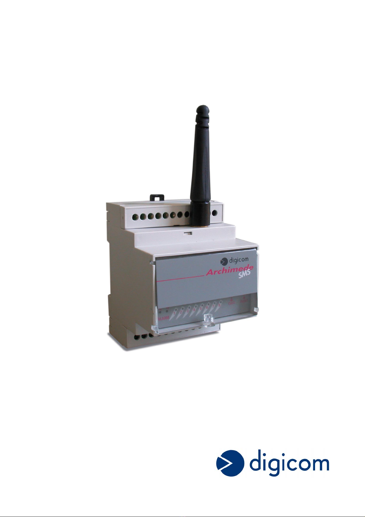
Alarm Input Characteristics
Permitted States
- Input Open
- Input Closed to Ground (0volt)
(with the input closed the maximum leakage current is
approx 1mA)
The maximum resistance between input
and ground 8 KΩ
Voltage Maximum Permitted +15 Vdc
Voltage Minimum Permitted -0,5 Vdc
Control Output Characteristics
Output 1 Dry Contact Normally Open
Max Current 3 A
2.1.2 Connecting the external antenna
After connecting the alarm inputs and if required the control output cabling the supplied
stub antenna can be fitted carefully positioning it and turning the SMA connector in a
clockwise direction.. In case of difficulty do not force it but ensure correct alignment.
Attention.
Best transmission and reception results are attained through placing the unit and its
antenna in a vertical direction and ensuring that no enclosure is shielding the radio
operation. In the event that the Archimede is installed in an enclosure or panel which
affects operation the use of a external antenna is recommended. Digicom Part no 8D4272
3.2 Metre External Antenna or 8E4150 0.8 Metre External Antenna can be supplied on
request.
2.1.3 Inserting the Subscriber Information Module (SIM)
The Archimede SMS functions using the Short Message Service (SMS) offered by most
mobile telephone operators. It is advisable to check with the supplier of your SIM that it is
enabled for SMS service. Some operators also offer EMS (Extended Message Service)
but this is not required for the Archimede SMS.
The SIM is a delicate item and should be handled with care never touching the gold
contact side as this can be damaged and cause faulty operation.
It is good practice to insert the new SIM into a normal telephone first to check functionality
and to disable the request for a PIN (Personal Identification Code) every time to SIM is
powered up.
A test SMS message should also be send to confirm the service is enabled and in the
case of prepaid SIM that sufficient credit airtime remains.
Ensure the Archimede is powered OFF
The SIM holder of the Archimede can be removed from the unit by pressing the latch with
a pencil or pen and carefully pulling out.
The SIM should be inserted into the holder ensuring the contacts are facing upwards and
that the bevelled edge opdf the SIM fits in the correct position.
Carefully insert the SIM holder into the Archimede and push gently until it is completely
home.

8
2.1.4 Power Requirements
The Archimede SMS can be powered by any DC or AC supply providing a range of 9.6 to
14.4 Volt is maintained.
Attention: In no circumstances must the power exceed 14.4 volts as serious damage will
occur to the unit and void all warranty.
2.1.5 Powering up for the first time
After installing the unit, connecting all alarm and control cables, inserting the SIM and
BEFORE connecting power it is necessary position the dipswitch in the Config position
and then the power can be connected.
Verify that the Pwr and Status LED’s are lit and that the 8 LED’s associated with the alarm
inputs go through a cyclic check.
After a few seconds the Archimede SMS will register with the mobile network and the
status LED should start to flash. In the event that it remains lit constantly it is an indication
that the unit has not registered with the network and the following items should be
checked:
•The SIM is inserted correctly and the holder pushed in.
•The PIN has been disabled
•The signal is insufficient in that area (check with another phone)
The configuration of the Archimede SMS is memorised on to the SIM used and for that
reason the self test and memory store can take around a minute.
In the event that the Archimede SMS was previously configured this configuration will be
memorised on the new SIM . (This eliminates to need to reconfigure alarms when a SIM is
replaced).
At the termination of this cyclic check only those inputpsut not yet configured remain lit. (In
the event of a new installation all will remain lit)
LED Indicators
LED STATE
PWR Off No Power
On Power present
Flashing Receiving an SMS Message
Status
On
-Searching for network
-SIM not present
-PIN requested (not disabled)
Flashing Registered on Network
1…8 Off Configuration phase = Input configured
Normal phase=Input NO alarm
On Configuration phase= Input not configured
Normal phase= Input= Alarm

9
3.Software Configuration
The programming of the Archimedes is carried out by sending SMS messages from a
normal cellular phone to the number of the SIM inserted in the unit. In this way the
Archimedes SMS stores the telephone numbers of the cellular phones to be informed in
the event of an alarm as well as the message to be sent for each alarm.
The programming will only be accepted by the unit if the dip switch is in the config position.
It is not advisable to use the SIM one uses every day as all the telephone numbers and
config can be overwritten easily. Each Archimede should have its own SIM and telephone
number.
3.1 Configuration Messages
The first thing to do is to label the Archimede and give it a name or identification number.
This identification will be sent by the Archimede whenever is sends alarm messages in
order that the receiver can identify the origin.
To configure the Archimede with its identification it must be sent the following SMS
message to the telephone number on its SIM.
# 0 # Identification Name #
Field Quantiy Characters Description
# 1 Delimit Character
0 1 Memory Location in Archimede
# 1 Delimit Character
Identification Max 20 Unit Name or Number
# 1 Delimit Character
For example the message #0#My House# would designate the unit to be in My House and
any messages sent from it would contain this information.
After sending this message the receiving Archimedes Pwr LED will flash for 5 secs to
indicate the message has been received and stored.
3.1.2 Configuration of the 8 Inputs
In order to configure the inputs of the Archimedes SMS it is necessary to assign:
•The name of the alarm
•Change of state to signal* or on a transition *
•To where the message should be sent
*As explained below the message will be sent on the change of state ie open to closed or
alternatively closed to open or just when transition occurs ei from closed to shut or vice
versa
The Archimede can be configured to send a message Alarm On when the alarm contact is
closed and send Alarm Off when the alarm contact is open again, or send a message
Alarm On only.

10
The former can be used to monitor door opening and closing for example whilst the latter
can be used for photoelectric alarm systems etc.
Firstly before carrying out this programming ensure that none of the inputs are in the alarm
condition.
Messages on Transitions Messages on Change of State
To configure each alarm it is necessary to send a message to the Archimedes as follows
# Number of
Contact
# Message # Transition # Tel 1 # Tel 2 # Tel 3 #
Field Quantiy Characters Description
# 1 Delimit Character
Contact No 1 1…8 Dependant on Contact No
# 1 Delimit Character
Message Max 20 Message to be sent to identify alarm
# 1 Delimit Character
Transition
1
Type of Transition/Change of State
T=Transition
S=StateChange
# 1 Delimit Character
No Tel 1 20 Max First Tel Number to send the Alarm Message
# 1 Delimit Character
No Tel 2 20 Max Second Tel Number to send the Alarm
Message
# 1 Delimit Character
No Tel 3 20 Max Third Number to send the Alarm Message
# 1 Delimit Character
•Note * The telephone number must always be inserted with its international code ie
+44 for UK, +49 for Germany , +33 for France etc
•All SMS messages must end with a # sign

11
Examples of configuration messages are as follows :
#1#Alarm Gas#T#+44123456789123#
#2#Gate Intrusion #S#+445678925567#+44567894567899#
#3#Water ON#T#+4467895657488#+4473263748596#+445476576879888#
After sending this message the receiving Archimedes Pwr LED will flash for 5 secs to
indicate the message has been received and stored.
A few moments after the alarm LED’s will turn off to indicate those alarms have been
configured.
If any of the alarms have been configured previously they will turn on briefly and then turn
off when they have been reconfigured..
In the case that the Archimede SMS receives a message (Pwr LED flashes) but alarm
LED’s stay on check the SMS message for any Syntax errors.
3.1.3 Alarm Configuration for Interuption of Power
In the event of power failure the Archimede SMS uses its internal battery to send a
message in order to inform users that a power failure has occurred.
After sending the message the Archimedes switches off to conserve the battery.
On return of the power the Archimedes sends a message informing the return of power
and recommences to check the status of alarm and report accordingly.
As an additional security measure the small battery inside the Archimedes is checked
regularly for charge and a message if the charge is below 8VDC. Under normal
circumstances the battery should last for a period of about 12 months before changing.
After the insertion of a new battery the unit should be reset by sending the following SMS
message to the Archimede SIM number.
# 9 # Message # Tel 1 # Tel 2 # Tel 3 #
Field Quantiy Characters Description
# 1 Delimit Character
9 1 9 is the memory location for Power Loss
# 1 Delimit Character
Message Max 20 Message to be sent to identify Power Alarm
# 1 Delimit Character
No Tel 1 20 Max First Tel Number to send the Pwr Alarm
Message
# 1 Delimit Character
No Tel 2 20 Max Second Tel Number to send the Pwr Alarm
Message
# 1 Delimit Character
No Tel 3 20 Max Third Number to send the Pwr Alarm Message
# 1 Delimit Character
•Note * The telephone number must always be inserted with its international code ie
+44 for UK, +49 for Germany , +33 for France etc
•All SMS messages must end with a # sign

12
Example of a configuration message is as follows :
#9#Power Failure #T#+4467895657488#+4473263748596#+445476576879888#
After sending this message the receiving Archimedes Pwr LED will flash for 5 secs to
indicate the message has been received and stored .This follows by a rapid flashing of the
Pwr Led for a further 5 secs then constantly on. In the event that the Pwr LED continues
to flash check the SMS message for any Syntax errors.
3.1.4 Configuring the Output Relay
The Archimede SMS has the capability of controlling an external device via an internal
relay whose contact outputs are on pins 19 and 20. This contact is normally open and can
be closed when the correct SMS message is received by the unit. This can be used via a
contact breaker or switch to shut a valve or turn on/off a switch .
To configure the output relay function an SMS message of the following structure must be
sent to the Archimede.
# 10 # Name # Tel 1 # Tel 2 # Tel 3 # Tel 4 # Tel 5 # Tel 6 #
Field Quantiy Characters Description
# 1 Delimit Character
10 2 10 is the memory location for Output relay
# 1 Delimit Character
Name of contact Max 20 Name (Message) to be sent to operate contact
# 1 Delimit Character
No Tel 1 20 Max 1st Tel Number allowed to send control
message
# 1 Delimit Character
No Tel 2 20 Max 2nd Tel Number allowed to send control
message
# 1 Delimit Character
No Tel 3 20 Max 3rd Tel Number allowed to send control
message
# 1 Delimit Character
No Tel 4 20 Max 4th Tel Number allowed to send control
message
# 1 Delimit Character
No Tel 5 20 Max 5th Tel Number allowed to send control
message
# 1 Delimit Character
No Tel 6 20 Max 6th Tel Number allowed to send control
message
# 1 Delimit Character
•Note * The telephone number must always be inserted with its international code ie
+44 for UK, +49 for Germany , +33 for France etc
•All SMS messages must end with a # sign

13
Example of a configuration message is as follows :
#10#Airconditioner#+4467895657488#+4473263748596#+445476576879888#
Note as with all commands the Archimede will only accept and act on messages
originating from predesignated telephones with Caller Identify enabled.
3.1.5 Conguration in Standby Mode
As previously stated the Archimede SMs must be powered in order to operate. However
there are instances where it is necessary to inhibit sending of SMS messages
automatically (for instance where the unit is used in an intrusion alarm system and the unit
must be activated/deactivated via a hidden switch or a timer).
Contacts 3 & 4 can be configured to toggle the unit into active or standby mode on any
transition across these inputs. In this case the number of alarm inputs managed is reduced
to 7.
When brought into active mode the Archimede executes a reset of all of the inputs states.
The Archimede can also be placed into STANDBY mode remotely by sending the following
message.
# 1 # STANDBY # Tel 1 # Tel 2 # Tel 3 # Tel 4 # Tel 5 # Tel 6 #
In the Standby mode the unit can be interrogated from a remote cellular phone using the
#TEST# message.
#TEST#
Field Quantiy Characters Description
# 1 Delimit Character
1 1 Contact 1 is used for Standby Function
# 1 Delimit Character
STANDBY 7 Enables Standby function
# 1 Delimit Character
No Tel 1 20 Max First Tel Number allowed to send control
message
# 1 Delimit Character
No Tel 2 20 Max First Tel Number allowed to send control
message
# 1 Delimit Character
No Tel 3 20 Max First Tel Number allowed to send control
message
# 1 Delimit Character
No Tel 4 20 Max First Tel Number allowed to send control

14
message
# 1 Delimit Character
No Tel 5 20 Max First Tel Number allowed to send control
message
# 1 Delimit Character
No Tel 6 20 Max First Tel Number allowed to send control
message
# 1 Delimit Character
•Note * The telephone number must always be inserted with its international code ie
+44 for UK, +49 for Germany , +33 for France etc
•All SMS messages must end with a # sign
Example of configuration messages are as follows :
#1#STANDBY#
(Use this message if the STANDBY function is to be executed locally only via Contacts
3&$)
#1#STANDBY#+4467895657488#+4473263748596#+445476576879888#
(Use this message if the STANDBY function is to be executed locally and remotely)
Note as with all commands the Archimede will only accept and act on messages
originating from predesignated telephones with Caller Identify enabled
3.1.6 Cancelling the Configuration
After initial configuration there may be circumstances when reconfiguration is necessary
due to change of names, alarm changes or remote authorised telephone numbers etc.
To cancel a particular alarm configuration it is sufficient to send a message to the alarm
number.
# CONTACT No #
Field Quantiy Characters Description
# 1 Delimit Character
Configuration
Address’s
2 Configuration Address’s
•0: Archimede Unit Name
•1…8 Alarm inputs
•9 Power Indication
•10 Output Contact
•99 Cancellation of entire configuration
# 1 Delimit Character

15
Examples:
#2# will cancel configuration for Alarm Input 2
#99# will cancel all configuration and restore factory defaults
#9# will cancel Pwr configuration
3.1.7 Verifying the Configuration.
To check the configuration in the Archimede SMS it is sufficient to send the following
message from an authorised cellular telephone.
#CONFIG#
After some seconds the Archimede will send the following configuration read type of
message:
ARCHIMEDE HOME
1) STANDBY
+44357839303999
+44546478390467
+44657494033300
2) ALARM GAS T
+44384759688493
+44364758697888
+44546389203444
3) N.C.
4) N.C.
5) N.C.
6) N.C.
7) N.C.
8) N.C.
9) Power ON
+44347586970000
+44435475869977
+44546778398993
10)AIR CONDITIONER
+44568765437896
+44568432786888
BATTERY CHARGED

16
3.1.8 Verify the GSM Signal Strength
To verify the GSM signal strength #CONFIG1# is sent to the ArchimedeSMS.
The unit will respond back with a message similar to this example.
ARCHIMEDE HOME
I VODAPHONE
GSM SIGNAL: GOOD
The signal strength can vary from EXCELLENT, GOOD and POOR and in the event
that the signal is POOR it is advisable to move the position of the unit or substitute
antenna for a higher gain one. (Contact Digicom).
In the event that the Archimede SMS is operated out of the SIM suppliers area it may
go into roaming in which case the message would indicate for example I VODAFONE
ROAMING.
Please note roaming charges can be substantially higher than normal.
3.2 Verifying and Alarm, Control and Battery Status.
To control the status of all the inputs, outputs and battery it is sufficient to send the
following message.
#TEST#
The Archimede after a few seconds will respond with the following type of message.
ARCHIMEDE HOME
1) STATE: ACTIVE
2) ALARM DOOR OFF
3) N.C.
4) ALARM GATE OFF
5) N.C.
6) ALARM GARAGE OFF
7) ALARM WINDOWS OFF
8) N.C.
9) POWER ON
10)AIR CONDITIONER ON
BATTERY: CHARGED
3.2.2 Management of the Control Relay
The control relay in the Archimede can be opened and closeed by sending an SMS
message as follows:
#OUTPUT ON#
(This causes the relay to close)
#OUTPUT OFF#
(This causes the relay to open)

17
After receipt of either of these messages the Archimede SMS will respond back with an
SMS message as follows:
ARCHIMEDE HOME
10) AIR CONDITIONER ON.
3.2.3 Management of Standby Function
To activate or deactivate the standby mode it is sufficient to send the following messages:
#DEACTIVATE#
(This will put the Archimede in Standby mode)
#ACTIVATE#
(This will put the Archimede in Active mode)
The unit wil then send a confirmation message as follows:
ARCHIMEDE HOME
STATE: DEACTIVATED
Note Archimede SMS will only accept SMS messages from authorised cellular telephones
with CLI enabled.
4. Signalling of Alarms
The Archimede SMS recognises a change of state on any of its alarm inputs and sends a
prewritten SMS message to any authorised cellular telephone in its configuration. It also
lights the corresponding LED associated with the specific input.
The procedure that the Archimede uses to send an SMS message is identical to that of a
normal cellular telephone in that it is sent to the telephone operators SMS service centre.
This service centre then relays the SMS message to the cellular telephone involved.
When using a normal cellular telephone to send an SMS message the telephone company
sends a “MESSAGE SENT” confirmation or a “MESSAGE FAILED” indication.
In the case of the Archimede if it receives a “MESSAGE FAILED” message it will await
approximately 1 minute before trying to send the message again. It will repeat this attempt
3 times to the first cellular telephone number and then proceed to make the attempt to the
second cellular number repeating the same procedure. This will continue on all available
cellular telephone numbers in the configuration.
In the case that the power is interrupted during the sending of an SMS message the
battery will continue for a maximum of 3 minutes after which the Archimede is turned off.
Alarm inputs to the unit can sometimes be intermittent due to bad contacts or other
galvanic disturbance causing multiple transitions. To avoid this type of malfunction
generating multiple SMS messages with associated cost the Archimede will only accept up
to 5 transitions on any one input in the period of 60 minutes. After this the particular input
is isolated and local intervention is required to reset the input circuitry by pressing the
associated reset button.
The user when receiving any indication of alarm will normally investigate locally and if
needs be rectify the cause of the alarm. Upon resetting any alarm the LED will be turned
off. If the LED remains on an alarm state continues to be present.

18
Note: SMS Alarm indications can differ dependant of the selection of State or Transition
Mode.
4.1 Alarm Input Messages
4.1.1 Example of alarm on contact 1
ARCHIMEDE HOME
1) ALARM GAS ON
(This type of alarm can be received whether the alarm mode is in the State or Transition
Mode)
4.1.2 Example of alarm termination on contact 1
ARCHIMEDE HOME
1) ALARM GAS OFF
(This type of alarm can only be received if the alarm mode is Transition Mode)
4.1.3 Alarm for power supply failure
ARCHIMEDE HOME
9) POWER SUPPLY OFF
BATTERY: CHARGED
(the battery can indicate CHARGED or UNCHARGED and in the case of UNCHARGED it
is necessary to replace the battery)
4.1.4 Alarm for power supply restored
ARCHIMEDE HOME
9) POWER SUPPLY ON
BATTEY CHARGED
4.1.5 Alarm for battery discharged
ARCHIMEDE HOME
BATTERY: DISCHARGED
For further information consult your local Digicom reseller or send an e-mail to
Table of contents
Other Digicom Security System manuals