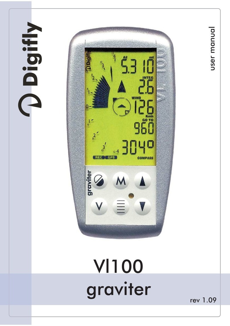
Digifly AIR-SE User manual

AIR_Manual_506a_ENG_rev_1.pdf Page 1/96
OWNER’s MANUAL
DIGIFLY AIR-SE AIR-BT AIR-BT-PITOT
Ver. 506a – English - Rev.1

AIR_Manual_506a_ENG_rev_1.pdf Page 2/96
CONGRATULATIONS
Thank you for choosing Digifly!
You have purchased a high technology instrument designed expressly for free-flight. The multiple functions
and flight data it provides effectively make it an on-board computer. Learning to use this instrument will
make your flying easier in terms of performance and safety; it will enable you to improve your flying
technique and make quicker piloting decisions thanks to the comprehensive flight information that is
provided. Another benefit is the ability to download and analyze your flight data afterwards.
The instrument has been designed to allow for future software developments to be easily incorporated via the
Internet.
Before you get started, make sure you have downloaded the free Digifly software for your AIR’s management,
AirTools
,
AirPages
and
AirUpdater
, from our website www.digifly.com
DIGIFLY INTERNATIONAL GUARANTEE
Dear Customer,
Thank you for purchasing this Digifly product which has been designed and
manufactured to the highest quality standards. Digifly warrants this product to be
free from defects in materials and workmanship for 3 years from the date of
purchase.
The Digifly guarantee applies provided the product is handled properly for its intended
use, in accordance with its operating instructions and upon presentation of the
original invoice or cash receipt, indicating the date of purchase, the dealer’s name,
the model and the serial number of the instrument.
The customer is however, responsible for any transportation costs. The unit must be
securely packaged for return.
The Digifly guarantee may not apply if:
- The documents have been altered in any way or made illegible.
- Repairs or product modifications and alterations have been executed by unauthorized person or service.
- Damage is caused by accidents including but not limited to lightning, water or fire, misuse or neglect, or
every malfunction not related to manufacturing defects of your instruments.
If your Digifly product is not working correctly or is defective, you must first contact your dealer, in order to
avoid unnecessary inconvenience. Please do not send the instrument back before previous approval.
Digifly Offices
Corporate Headquarters
Digifly Europe Srl
Bologna
Italy
Phone : +39 370 1167217
Web : www.digifly.com
E-mail : info@digifly.com
North, Central and South American Headquarters
Digifly USA
St. Augustine, FL
USA
Phone : +1 (240) 343-5987
Web : www.digiflyusa.com
E-mail : flydigifly@gmail.com

AIR_Manual_506a_ENG_rev_1.pdf Page 3/96
1
INDEX
1
INDEX .................................................................................................................................................3
2
GETTING STARTED ..............................................................................................................................7
2.1 CONNECTIONS, SENSORS AND AIR MANAGEMENT SOFTWARE............................................................................7
2.2 BATTERY ...............................................................................................................................................................7
2.2.1 BATTERY RECHARGE...................................................................................................................................7
2.2.2 EXTERNAL POWER SUPPLY.........................................................................................................................8
2.3 KEYBOARD -NORMAL OR LONG KEY PRESS ........................................................................................................8
2.4 POWER ON &OFF .................................................................................................................................................8
2.5 DISPLAY CONTRAST ADJUSTMENT.......................................................................................................................8
2.6 MENU ...................................................................................................................................................................8
2.6.1 STANDARD FIELDS EDITING ........................................................................................................................9
2.6.2 ALPHANUMERICAL FIELDS EDITING............................................................................................................9
2.7 MULTI LANGUAGE HELP .......................................................................................................................................9
2.8 RESTORE FACTORY SETTINGS.............................................................................................................................9
2.9 RESET...................................................................................................................................................................9
3
QUICK REFERENCE GUIDE ................................................................................................................ 10
3.1 SYMBOLS ...........................................................................................................................................................10
3.2 PAGES ................................................................................................................................................................11
3.2.1 CONFIGURABLE PAGES ............................................................................................................................11
3.2.2 MANUAL PAGE SWITCHING .......................................................................................................................12
3.2.3 AUTOMATIC PAGE SWITCHING (INTELLIFY) ...............................................................................................12
3.3 COMPETITION PAGES .........................................................................................................................................13
3.3.1 PAGE 1 COMP FLIGHT (THERMAL) AND PAGE 2 COMP FLIGHT (GLIDE) ..................................................13
3.3.2 PAGE 3 COMP START (THERMAL) AND PAGE 4 COMP START (GLIDE).....................................................14
3.3.3 PAGE 5 COMP GOAL (THERMAL) AND PAGE 6 COMP GOAL (GLIDE)........................................................15
3.4 CROSS COUNTRY (XC) PAGES.............................................................................................................................16
3.4.1 PAGE 7 XC (THERMAL) ..............................................................................................................................17
3.4.2 PAGE 8 XC (GLIDE).....................................................................................................................................18
3.5 PAGE 9COMPASS..............................................................................................................................................19
3.6 PAGE 10 RELAX ..................................................................................................................................................20
3.7 PAGE 11 AHRS....................................................................................................................................................20
3.8 PAGE 12 MAP .....................................................................................................................................................21
3.9 PAGE 13 MASTER INFO GPS PAGE .....................................................................................................................22
3.9.1 GPS STATUS INFORMATION ......................................................................................................................23
3.9.2 LATITUDE & LONGITUDE COORDINATES ...................................................................................................23
3.9.3 LATITUDE & LONGITUDE COORDINATES OPTIONS ...................................................................................23
3.9.4 GPS SIGNAL QUALITY (HDOP)....................................................................................................................23
3.9.5 GPS ALTITUDE............................................................................................................................................
23
3.9.6 GPS DIRECTION (TRK) ...............................................................................................................................23
3.9.7 GPS GROUND SPEED.................................................................................................................................23
3.9.8 REAL TIME NAVIGATION MANAGER / SKIP WAYPOINT .............................................................................23
3.9.9 CREATING A NEW WAYPOINT USING THE CURRENT POSITION (MARK) ...................................................24
3.9.10 NAVIGATION TO “HOME” WAYPOINT (GOTO HOME)..................................................................................24
3.9.11 DEACTIVATING THE CURRENT NAVIGATION (CLEAR NAV) ........................................................................24
3.9.12 DATE & TIME..............................................................................................................................................24
4
MAIN FUNCTIONS............................................................................................................................. 25
4.1 ALTIMETERS .......................................................................................................................................................25
4.1.1 AGL ALTIMETER.........................................................................................................................................25
4.1.2 ALTIMETERS’ SETTINGS ..........................................................................................................................25
4.1.3 ALTIMETERS’ SETTINGS ...........................................................................................................................25
4.1.4 MAXIMUM ALTITUDE ALARM.....................................................................................................................26
4.2 VARIOMETERS....................................................................................................................................................27
4.2.1 11-SENSORS VARIOMETER WITH SELF - ADAPTIVE SENSITIVITY .........................................................27
4.2.2 DIGITAL VARIO ...........................................................................................................................................27
4.2.3 ANALOGICAL VARIO ...................................................................................................................................27

AIR_Manual_506a_ENG_rev_1.pdf Page 4/96
4.2.4 INTEGRATED (AVERAGE) VARIO ................................................................................................................27
4.2.5 NET VARIO (WITH OPTIONAL PITOT TUBE).................................................................................................27
4.2.6 INTEGRATED VARIO / NET VARIO AUTOMATIC SWITCH ............................................................................28
4.2.7 McCREADY (WITH OPTIONAL PITOT TUBE) ................................................................................................28
4.2.8 EQUIVALENT McCREADY (WITH OPTIONAL PITOT TUBE) ..........................................................................28
4.2.9 TOTAL ENERGY COMPENSATION (WITH OPTIONAL PITOT TUBE)..............................................................29
4.2.10 ACOUSTIC VARIO........................................................................................................................................30
4.2.11 ACOUSTIC VARIO PRE-THERMAL TONE .....................................................................................................30
4.2.12 VARIO SIMULATOR.....................................................................................................................................30
4.3 AIRSPEED (WITH OPTIONAL PITOT TUBE) ...........................................................................................................31
4.3.1 SPEED TO FLY (WITH OPTIONAL PITOT TUBE) ...........................................................................................31
4.3.2 SPEED DIFFERENCE (WITH OPTIONAL PITOT TUBE) .................................................................................32
4.3.3 STALL ALARM (WITH OPTIONAL PITOT TUBE) ...........................................................................................32
4.3.4 AIRSPEED CALIBRATION (WITH OPTIONAL PITOT TUBE)...........................................................................32
4.4 POLAR (WITH OPTIONAL PITOT TUBE) .................................................................................................................33
4.5 BAROMETER.......................................................................................................................................................34
4.6 TIME ...................................................................................................................................................................34
4.7 CHRONOGRAPH..................................................................................................................................................34
4.8 PILOT’S NAME &GLIDER’S INFO ........................................................................................................................34
5
ADVANCED FUNCTIONS .................................................................................................................... 35
5.1 MAGNETIC COMPASS (HEADING) .......................................................................................................................35
5.2 G-METER ............................................................................................................................................................35
5.3 INERTIAL PLATFORM (AHRS) ..............................................................................................................................35
5.3.1 PITCH .........................................................................................................................................................35
5.3.2 ROLL ..........................................................................................................................................................35
5.3.3 YAW............................................................................................................................................................35
6
GPS FUNCTIONS............................................................................................................................... 36
6.1 INTEGRATED GPS RECEIVER WITH 99 CHANNELS .............................................................................................36
6.2 GPS STATUS INFORMATION...............................................................................................................................36
6.3 GPS SIGNAL QUALITY (HDOP) .............................................................................................................................36
6.4 EARTH MODEL USED FOR DISTANCE CALCULATION ..........................................................................................36
6.5 TOLERANCE USED FOR DISTANCE CALCULATION ..............................................................................................36
6.6 LATITUDE &LONGITUDE COORDINATES.............................................................................................................36
6.7 LATITUDE &LONGITUDE COORDINATES OPTIONS .............................................................................................36
6.8 GPS ALTITUDE ....................................................................................................................................................36
6.9 GPS GROUND SPEED........................................................................................................................................36
6.10 GPS DIRECTION (TRK) ........................................................................................................................................37
6.11 GROUND EFFICIENCY (GLIDE RATIO) ..................................................................................................................37
6.12 WIND SPEED AND DIRECTION INDICATION USING GPS .................................................................................37
6.13 LAST THERMAL POSITION, DISTANCE &HEIGHT INFORMATION.........................................................................38
6.14 THERMAL ASSIST...............................................................................................................................................38
6.15 THERMAL TUTOR ................................................................................................................................................38
6.16 PLOTTER.............................................................................................................................................................39
6.17 MAP ....................................................................................................................................................................40
6.17.1 TERRAIN (first layer): .................................................................................................................................
40
6 .17. 2 NAV (second layer).....................................................................................................................................42
6 .17. 3 FAI-TRANGLE ASSISTANT (third layer) ......................................................................................................43
6 .17. 4 AIRSPACE CTR (fourth layer)......................................................................................................................44
6.18 3D AIRSPACE MANAGER (CTR) ...........................................................................................................................44
6.18.1 UPLOAD AND ENABLE AIRSPACE CTRs TO THE DIGIFLY AIR ....................................................................44
6.18.2 VISUAL AND ACOUSTIC DISTANCE WARNING TO THE CTR .......................................................................46
6.18.3 CTR’s HORIZONTAL DISTANCE INDICATOR ...............................................................................................46
6.18.4 CTR’s VERTICAL DISTANCE INDICATOR .....................................................................................................46
7
WAYPOINT MANAGEMENT ................................................................................................................ 47
7.1 WAYPOINT DATABASES: COMPETITION &USER ................................................................................................47
7.1.1 MANUALLY CREATING A NEW WAYPOINT..............................................................................................47
7.1 . 2 CREATING A NEW WAYPOINT USING THE CURRENT POSITION (MARK) ...........................................47
7.1 . 3 EDIT WAYPOINT.........................................................................................................................................47

AIR_Manual_506a_ENG_rev_1.pdf Page 5/96
7.1 . 4 DELETE WAYPOINT ...................................................................................................................................47
8
NAVIGATE TO A SINGLE WAYPOINT (GOTO)..................................................................................... 48
8.1 ACTIVATING NAVIGATION TO AWAYPOINT (GOTO) ..........................................................................................48
8.1.1 NAVIGATION TO WAYPOINT HOME (GOTO HOME) .................................................................................48
8.1.2 NAVIGATION TO THE NEAREST LANDING ZONE (GOTO LANDING)............................................................48
8.1.3 NAVIGATION TO THE NEAREST WAYPOINT (GOTO NEAREST) ..............................................................48
8.1.4 NAVIGATION TO A GENERIC WAYPOINT (GOTO)....................................................................................49
8.1.5 DEACTIVATING NAVIGATION TO A WAYPOINT (CLEAR NAV) ..................................................................49
8.2 NAVIGATION FUNCTIONS TO ASINGLE WAYPOINT (GOTO) .................................................................................50
8.2.1 DIRECTION, DISTANCE & HEIGHT TO THE CURRENT WAYPOINT .............................................................50
8.2.2 COMPASS TO THE CURRENT WAYPOINT...................................................................................................50
8.2.3 REQUIRED GLIDE RATIO TO THE CURRENT WAYPOINT.......................................................................50
8.2.4 ARRIVAL HOUR, ARRIVAL TIME TO THE CURRENT WAYPOINT ...........................................................50
8.2.5 HSI GRAPHIC INDICATION TO THE CURRENT WAYPOINT ....................................................................50
9
ROUTE MANAGEMENT ..................................................................................................................... 51
9.1 ROUTES OVERVIEW............................................................................................................................................51
9.2 VISUALIZING WAYPONT INFO OF AROUTE.......................................................................................................51
9.3 INSERT AWAYPOINT IN AROUTE ....................................................................................................................51
9.4 SUBSTITUTING AWAYPOINT IN AROUTE ........................................................................................................51
9.5 MODIFY AWAYPOINT IN AROUTE (PARAMETER CHANGE)..............................................................................52
9.6 DELETE AWAYPOINT OF AROUTE ....................................................................................................................53
9.7 DELETING AROUTE...........................................................................................................................................53
10
ROUTE NAVIGATION.......................................................................................................................... 54
10.1 ACTIVATING AROUTE ........................................................................................................................................54
10.2 DE-ACTIVATING AROUTE (CLEAR NAV)..............................................................................................................54
10.3 OPTIMIZED NAVIGATION....................................................................................................................................54
10.4 NAVIGATION TO ASTANDARD WAYPOINT ...........................................................................................................55
10.4.1 DIRECTION, DISTANCE & HEIGHT OVER THE CURRENT WAYPOINT..........................................................55
10.4.2 COMPASS TO THE CURRENT WAYPOINT ...................................................................................................56
10.4.3 REQUIRED GLIDE RATIO TO CURRENT WAYPOINT .............................................................................56
10.4.4 ARRIVAL TIME & TIME TO CURRENT WAYPOINT .......................................................................................56
10.4.5 HSI GRAPHIC NAVIGATION TO CURRENT WAYPOINT...............................................................................56
10.4.6 DISTANCE & HEIGHT OVER THE ARRIVAL WAYPOINT (GOAL)..................................................................56
10.4.7 REQUIRED GLIDE RATIO TO GOAL............................................................................................................57
10.4.8 ARRIVAL TIME & TIME TO GOAL ................................................................................................................57
10.4.9 CROSS TRACK ERROR (XT)........................................................................................................................57
10.5 NAVIGATION TO THE START WAYPOINT (GATE) .................................................................................................58
10.5.1 STARTING TIME (TSTART) ..........................................................................................................................59
10.5.2 REMAINING TIME TO START (CSTART) .....................................................................................................59
10.5.3 EXPECTED ARRIVAL TIME TO START LINE (ESTART)................................................................................59
10.5.4 REQUIRED SPEED TO START THE CYLINDER LINE (STS) .........................................................................59
10.5.5 CHOOSING A DIFFERENT START GATE TIME IN A COMPETITION ROUTE..................................................59
10.6 SKIP WAYPOINT SHORTCUT................................................................................................................................59
10.7 OPERATION CHECKLIST BEFORE ATASK .........................................................................................................60
11
FLIGHT RECORDER........................................................................................................................... 61
11.1 ACTIVATING /DE-ACTIVATING THE FLIGHT RECORDER ......................................................................................61
11.1.1 RECORDING MODE: AUTOMATIC START “AUT” .........................................................................................61
11.1.2 RECORDING MODE: ALWAYS ACTIVE “ALW” .............................................................................................61
11.1.3 RECORDING MODE “OFF”..........................................................................................................................61
11.2 RECORDING RATE..............................................................................................................................................62
11.3 LOG BOOK MANAGEMENT (LOG BOOK) ...........................................................................................................62
11.4 INTEGRATED IGC FILE.........................................................................................................................................62
12
ADDITIONAL MEMORY CARD ............................................................................................................. 63
12.1 MICRO SD MANAGER..........................................................................................................................................63
13
CONNECTIONS & INTERFACES .......................................................................................................... 64
13.1 USB CABLE CONNECTION...................................................................................................................................64

AIR_Manual_506a_ENG_rev_1.pdf Page 6/96
13.2 BLUETOOTH CONNECTION (AIR BT ONLY) .........................................................................................................66
13.2.1 BLUETOOTH “PAIRING”..............................................................................................................................66
14
SOFTWARE....................................................................................................................................... 67
14.1 AIR MANAGEMENT SOFTWARE...........................................................................................................................67
14.1.1 DIGIFLY AIRTOOLS SOFTWARE (PC / Mac)................................................................................................67
14.1.2 DIGIFLY AIRPAGES SOFTWARE (PC / Mac) ...............................................................................................68
14.1.3 GPSDUMP SOFTWARE (PC, Mac, ANDROID) .............................................................................................71
14.2 DIGIFLY AIRUPDATER SOFTWARE FOR FIRMWARE UPDATE (PC, MAC) ...............................................................74
14.2.1 FIRMWARE UPDATE PROCEDURE .............................................................................................................74
15
LIVE TELEMETRY WITH THE INTEGRATED DIGI-FLYBOX ...................................................................... 76
15.1 ACTIVATING THE DIGIFLY’S TELEMETRY DATA OUTPUT DIGI-FLYBOX ..................................................................76
15.1.1 Digi-FLYBOX TELEMETRY DATA TYPE SELECTION.....................................................................................77
15.2 DIGI-FLYBOX TELEMETRY TO LK8000 .................................................................................................................79
15.3 DIGI-FLYBOX TELEMETRY TO XCSOAR .................................................................................................................81
15.4 DIGI-FLYBOX TELEMETRY TO XCTRACK ...............................................................................................................83
15.5 DIGI-FLYBOX TELEMETRY TO TOPHAT ..................................................................................................................85
15.6 DIGI-FLYBOX LIVE TRACK &TELEMETRY TO GPSDUMP.......................................................................................87
15.7 DIGI-FLYBOX LIVE TRACK &TELEMETRY TO TTLIVETRACK24..............................................................................89
16
APPENDIX ........................................................................................................................................ 91
16.1 DIGIFLY AIR STANDARD ACCESSORIES............................................................................................................91
16.2 OPTIONAL ACCESSORIES...................................................................................................................................91
16.3 TECHNICAL FEATURES.......................................................................................................................................91
16.3.1 STANDARD FUNCTIONS.............................................................................................................................91
16.3.2 ADVANCED FUNCTIONS .............................................................................................................................92
16.3.3 GPS FUNCTIONS ........................................................................................................................................92
16.3.4 GENERAL SPECIFICATIONS........................................................................................................................92
16.4 MAIN SET UP MENU PARAMETERS.....................................................................................................................94
16.5 ADV-SETUP PARAMETERS MENU (ADVANCED SETUP)......................................................................................95
16.6 VARIOMETER SETUP PARAMETERS ..................................................................................................................95

AIR_Manual_506a_ENG_rev_1.pdf Page 7/96
2
GETTING STARTED
2.1
CONNECTIONS, SENSORS and AIR MANAGEMENT SOFTWARE
Main Features :
oDual purpose mini USB socket allows the Digifly AIR to be recharged with the supplied Digifly 5v charger and,
additionally, to be connected to a personal computer or Mac for configuration & flight data management.
oMicro SD card slot; use Class 10 cards with 8 to 32GB formatted FAT32.
oBluetooth System -AIR BT model only- for wireless communication with other electronic devices
oIntegrated Digi-FlyBox to send its Telemetry to another electronic device, via USB cable or via Bluetooth. This
means sending the information from its sensors through a wireless communication system.
oGPS receiver - 99 channels
oBarometer (atmospheric pressure sensor)
oIntegrated anemometer – pitot tube (optional)
oAHRS – 3-axis inertial platform: Spatial position and direction vectors
relative to the 3 spatial axes.
o3-axis magnetic compass
o3-axis accelerometer
oFree digital worldwide topographic maps.
oAirspace upload and management.
oThree Free management software programs both for PC or Mac: AirTools, AirPages and AirUpdater.
Optional Features:
oIntegrated anemometer – Pitot Tube System
2.2
BATTERY
The main power is supplied by an internal rechargeable high capacity lithium battery, which has no memory
effect, so it can be partially recharged, without affecting the battery’s life. It also has a very low self-discharge
rate (about six months) and works very well at low temperatures. A fully charged battery will power the
instrument for over 30 hours: when the battery icon starts to flash, you have approximately 4 hours left of
battery power.
Make sure your instrument is fully charged any time you put store it for a longer period of time (e.g. end of the
flying season) or any time you know you won’t be using it for a while.
To avoid permanent battery damage, you must ensure that it receives a full charge within 3 months of the last
full charge.
2.2.1
BATTERY RECHARGE
To recharge the instrument, connect it to a power source with the USB cable.
Input: DC 5v is required and a 1A is recommended.
The required time for a full charge is about 8 hours.
There are no problems if you leave the vario charging for more than 8 hours, as the vario automatically switches
to a “maintain mode” preventing the battery from being overcharged.
The Digifly AIR’s lithium battery has no “memory effect”, so it can be also partially charged.
miniUSB
microSD slot

AIR_Manual_506a_ENG_rev_1.pdf Page 8/96
2.2.2
EXTERNAL POWER SUPPLY
The mini USB socket can be used to power the instrument and simultaneously charge the internal battery.
An external stabilized 5VDC power supply (e.g. a solar panel, external power bank, etc.) with a minimum of
150mA is necessary to turn the instrument on; any excess power will be used to charge the internal lithium
battery. Proper solar panels are suitable to power the instrument.
Important Notice
: do not keep your Digifly AIR connected to its USB port in flight or in any situation where the
USB cable could create an undesired movement to the charging port, applying force on the soldered connection
of the mini USB, resulting in its detachment from the board. This also applies when you carry your AIR in your
harness or a backpack: do not have the USB cable connected to it.
2.3
KEYBOARD - NORMAL OR LONG KEY PRESS
The time length you keep the keys pressed on your Digifly instrument selects the available functions.
For a
normal press:
press the button for less than a second
For a
LONG PRESS:
keep the button pressed down for at least 2 seconds
Note
: When not specified, the key press has to be considered as a normal key press (less than a second).
2.4
POWER ON & OFF
To
turn
your Digifly AIR
on
, press the key for at least 4 seconds, until you hear it “beep”.
To
turn
your Digifly AIR
off
, press the key for at least 4 seconds, until you hear it “beep”. If the logger is
recording, you will be prompted to confirm your choice by pressing the key or, to cancel, press the key;
it will automatically cancel the request within 3 seconds of no input.
After switching your Digifly off, wait at least 5 seconds before attempting to turn it on again; this prevents
unwanted operation.
After turning your Digifly on, the first screen briefly shows the vario model, pilot name (if set), microSD status,
logger status, vario serial number, firmware version and battery voltage.
2.5
DISPLAY CONTRAST ADJUSTMENT
To change the contrast of the display, press the key to enter the “MAIN
SETUP” menu, select CTRS (
MAIN SETUP \ n. 1 CTRS)
, go to the edit mode
pressing the key, set the preferred contrast using the keys: ‘arrow UP’
or ‘arrow DOWN’ , then save the changes by pressing the key.
2.6
MENU
To navigate the menus of your instrument, press the key (“MENU”
function).
To select the sub-menus, scroll UP or DOWN the list using the arrow
keys, then confirm your choice pressing the key (“ENT” function).
To exit and get back to the main screen press the key (“ESC” function).

AIR_Manual_506a_ENG_rev_1.pdf Page 9/96
2.6.1
STANDARD FIELDS EDITING
To change parameters and settings, select the parameter you want to change by scrolling UP or DOWN using the
keys, press the key (“EDIT” function) to enter in the edit mode.
To change the value of the selected parameter, use the keys to select the new value, each parameter’s
change is automatically saved (“AUTOSAVE” function) when you exit; keeping the , keys pressed
activates the quick parameter change (“AUTOREPEAT”) function.
To exit from the edit function, press the key (“ESC” function).
2.6.2
ALPHANUMERICAL FIELDS EDITING
Changing the alphanumerical fields is different from the normal editing described above, because it is possible
to modify every single character of the field.
To modify the field, press the key (“EDIT” function) that activates the edit mode.
Use the arrow keys to change the character shown in reverse mode on the display. Each parameter’s
change is automatically saved (“AUTOSAVE” function) when you exit; a LONG PRESSof the arrow keys activates
the quick parameter change (“AUTOREPEAT”) function. Pressing will take you straight to the alphabet.
By pressing the key, you will shift to the character on the right and edit it; by pressing the key repeatedly
you will scroll towards the right through all the individual fields until you go back to the first one. A LONG PRESS of
the key moves back to the left; to exit press the key.
2.7
MULTI LANGUAGE HELP
“Help” texts are available in the setup menus to guide you through the parameters. It is possible to set a
language for these texts on the MAIN SETUP menu (
MAIN SETUP \ n. 2 LANG
) by selecting the preferred
language. The change will be automatically saved when you exit.
Another option is for you to create your own files using AirTools, save it and then upload it to the instrument.
You cannot upload one single line at a time, you upload all the helps contained in a menu (Main, Advanced or
Variometer).
Important
: after every firmware update, it is necessary to update the help file containing the help messages as
well. The help file update can be performed from your PC/Mac using Digifly AirTools, function: “upload HELP”.
2.8
RESTORE FACTORY SETTINGS
To restore the factory settings (default values for all parameters), with the instrument OFF, simultaneously hold
down the & keys, until the message “FACTORY SET?” appears. Confirm with or cancel with .
2.9
RESET
If a system crash occurs (resulting in the instrument freezing), press the (arrow down) and the (power)
buttons at the same time for at least 5 seconds; this will force the instrument to turn off and reset, then turn
your instrument back on normally. This reset will
not
erase any data or settings from your instrument.

AIR_Manual_506a_ENG_rev_1.pdf Page 10/96
3
QUICK REFERENCE GUIDE
3.1
SYMBOLS
Battery level
Bluetooth activated
Static icon = GPS FIX valid (GPS position available)
Blinking icon = low GPS signal (GPS position NOT available)
Flight recorder on
Volume level
Direction towards the center of the current Waypoint
Direction towards the optimized point of the current WP’s cylinder
Direction towards the optimized point of the current WP’s cylinder
Last thermal position
Wind direction (from where it is coming)

AIR_Manual_506a_ENG_rev_1.pdf Page 11/96
3.2
PAGES
The Digifly AIR features 13 pages: 12 configurable pages and one main page with GPS info, called the “
MASTER
INFO GPS PAGE
" which, for safety reasons, cannot be changed or disabled.
3.2.1
CONFIGURABLE PAGES
There are 12 configurable pages; each one is linked to one of the 12 configurable parameters (from
MAIN
SETUP\ n. 26 PG01
till
MAIN SETUP\ n. 37 PG12
) and for each page it is possible to configure a different layout:
OFF
= the layout view of the page is disabled (the page will be skipped)
STD
= it will show the corresponding Digifly standard layout
USR
= it will show the corresponding user layout created and uploaded by the user using the
free
Digifly
program
AirPages
(for more details about software usage refer to chapter 14.1.2).
REFERENCE TO NAME AND CONTENT OF CUSTOMIZABLE PAGES
PG01 page_1_IntelliComp_flight_thermal
OFF
/STD/USR
PG02 page_2_IntelliComp_flight_glide
OFF
/STD/USR
PG03 page_3_IntelliComp_start_thermal
OFF
/STD/USR
PG04 page_4_IntelliComp_start_glide
OFF
/STD/USR
PG05 page_5_IntelliComp_goal_thermal
OFF
/STD/USR
PG06 page_6_IntelliComp_goal_glide
OFF
/STD/USR
PG07 page_7_IntelliXc_cross_thermal OFF/
STD
/USR
PG08
page_8_IntelliXc_cross_glide
OFF/
STD
/USR
PG09 page_9_compass OFF/
STD
/USR
PG10 page_10_relax OFF/
STD
/USR
PG11 page_11_ahrs OFF/
STD
/USR
PG12 page_12_map OFF/
STD
/USR
Default page settings (in bold type) : PG1=OFF, PG2=OFF, PG3=OFF, PG4=OFF, PG5=OFF, PG6=OFF, PG7=STD,
PG8=STD, PG9=STD, PG10=STD, PG11=STD, PG12=STD

AIR_Manual_506a_ENG_rev_1.pdf Page 12/96
3.2.2
MANUAL PAGE SWITCHING
To manually change the pages, press the key to go forward or the key to go back.
You can manually switch pages even if you are in “Intellifly” mode.
3.2.3
AUTOMATIC PAGE SWITCHING (INTELLIFY)
The automatic page-switching among the different pages is automatically managed by the
Intellifly
system,
which recognizes the type of in-flight situation you are in at all times.
Each type of in-flight situation is associated to a different set of pages (2 per set):
Pages 1 and 2 are associated to a “Competition flying while navigating towards a standard waypoint” situation.;
Pages 3 and 4 are associated to a “Competition flying while navigating towards a Start waypoint”;
Pages 5 and 6 are associated to a “Competition flying while navigating towards a Goal waypoint”;
Pages 7 and 8 are associated to a “Free Cross Country flying” situation;
Each set of pages is formed by a “THERMAL” and a “GLIDE” version. The automatic page switching within each
set of pages follows these criteria: It will switch to the “THERMAL” page when it notices a thermal that lasts
longer than the value set on the
VARIOMETER SETUP\ n. 17 THET
parameter (default setting 2 seconds) and
you make a turn to fly into it; it will switch to the “GLIDE” page when you fly “straight” for a period of time,
longer than the value set on the
VARIOMETER SETUP\ n. 16 CRUT
(default setting 15 seconds).
The
MAIN SETUP\ n. 38 IFLY
parameter sets the mode in which the Intellifly system will work :
o
IFLY=OFF
: automatic page switching is disabled.
o
IFLY=CMP
:
automatic page switching is in “Competition” mode
:
when your current wpt is a standard one, it will automatically switch between PG01 and PG02;
when your current wpt is the START, it will automatically switch between PG03 and PG04;
when your current wpt is the one before last on your route (GOAL), it will automatically switch between
PG05 and PG06.
If I manually switch to a page outside the PG01-PG06 range, while on IFLY = CMP mode, the automatic
switching will be paused until I manually switch back to one of the pages of the PG01-PG06 range.
Remember to verify that all 6 competition pages are active:
MAIN SETUP\ n.26 PG01
to
MAIN SETUP\
n.31 PG06
=
STD
or
USR
(in case you have uploaded your own pages).
o
IFLY=XC
: automatic page switching will be on “Cross Country” mode (default setting): it will automatically
switch between PG07 e PG08.
PG07 is the XC – Thermal page and PG08 is the XC – Glide page.
If I manually switch to a page different from PG07 or PG08, the automatic page switching mode will be
paused until I manually switch back to a page among PG07 or PG08.
Remember to check that the 2 Cross Country pages are active:
MAIN SETUP\ n.32 PG07
and
MAIN
SETUP\ n.33 PG08
on
STD
or
USR
(in case you have uploaded your own pages).

AIR_Manual_506a_ENG_rev_1.pdf Page 13/96
3.3
COMPETITION PAGES
Pages 1-6 are designed for competition flying:
opages 1 and 2 provide information regarding navigation towards a standard waypoint;
opages 3 and 4 provide information regarding navigation towards the START;
opages 5 and 6 provide information regarding navigation to the final waypoint (GOAL);
N.B. Pages 1 to 6 are disabled by default, in order to activate them, you must set their 6 parameters (
MAIN
SETUP\ n. 26 PG01
to
MAIN SETUP\ n. 31 PG06
) to
STD
(to display the standard page your Digifly comes with)
or on
USR
(to display the custom pages called “USER” previously uploaded to the Digifly using our free software
AirPages).
3.3.1
PAGE 1 COMP FLIGHT (THERMAL) AND PAGE 2 COMP FLIGHT (GLIDE)
Pages 1 and 2 provide information regarding navigation toward a standard waypoint:
oyour current waypoint’s name
oflight direction towards the optimized point of the current waypoint’s cylinder(
FOLLOW ME
)
orequired glide to reach the optimized point of your current waypoint’s cylinder
oshortest distance to the current’s waypoint cylinder (
D0
)
odistance to the optimized point of the current waypoint’s cylinder (
D1
)
oexpected height of arrival to the optimized point of the current waypoint’s cylinder (
H1
)
oCross Track error regarding the route connecting the centers of the waypoint cylinders (
XT
)
When the instrument recognizes a thermal and you make a turn to fly into it, the automatic page switching
feature will take you to PG01
COMP FLIGHT (THERMAL), which besides the navigation info will also display the
information regarding the thermal itself: Thermal Assist
will help you center the thermal’s core better, (DT) will
show you the distance to the thermal’s core and the A3 Altimeter which will show you the altitude difference as
you thermal and will automatically reset (go to zero) when you enter the thermal.
When flying “on a straight line” for a period of time greater to the value set in the
VARIOMETER SETUP\ n. 16
CRUT
parameter (default 15sec) the instrument will automatically switch to PG02
COMP FLIGHT (GLIDE)
PAGE 1 COMP FLIGHT (THERMAL) PAGE 2 COMP FLIGHT (GLIDE)

AIR_Manual_506a_ENG_rev_1.pdf Page 14/96
3.3.2
PAGE 3 COMP START (THERMAL) AND PAGE 4 COMP START (GLIDE)
Pages 3 and 4 provide information regarding the navigation towards the START Waypoint of your route:
oCurrent waypoint’s name
oFlight direction towards the optimized point of the current waypoint’s cylinder (
FOLLOW ME
)
oRequired glide ration to reach the optimized point on the current waypoint’s cylinder
oRequired speed to reach to the Start line (cylinder) exactly a the Start Gate’s opening time (
SS
)
oShortest distance to the nearest point on the current waypoint’s cylinder (
D0
)
oDistance to the optimized point on the current waypoint’s cylinder (
D1
)
oCurrent time (
RT
)
oTime remaining (countdown) to the Start Gate opening time (
CS
)
oApproximate time of arrival to the cylinder line of the Start waypoint l (
ES
)
When the Digifly recognizes a thermal and you make a turn to fly into it, the Digifly will automatically switch to
PG03
(THERMAL)
, which besides the navigation information, will also display the
Thermal Assist
instrument for
thermal core centering.
When you fly “on a straight line for a period of time greater than the value set on the
VARIOMETER SETUP\ n. 16
CRUT parameter
(default 15sec), the instrument will automatically switch to PG04
COMP START (GLIDE)
PAGE 3 COMP START THERMAL PAGE 4 COMP START GLIDE

AIR_Manual_506a_ENG_rev_1.pdf Page 15/96
3.3.3
PAGE 5 COMP GOAL (THERMAL) AND PAGE 6 COMP GOAL (GLIDE)
Pages 5 and 6 provide information regarding navigation towards the arrival waypoint (GOAL) of your route:
oCurrent waypoint’s name
oFlight direction towards the optimized point of the current waypoint’s cylinder (
FOLLOW ME
)
oRequired glide ration to reach the optimized point on the current waypoint’s cylinder
oShortest distance to the nearest point on the current waypoint’s cylinder (
D0
)
oDistance to the optimized point on the current waypoint’s cylinder (
D1
)
oRequired glide to reach the cylinder of the route’s last waypoint (GOAL)
oEstimated arrival height over the cylinder of the route’s last waypoint (GOAL) (
HA
)
oDistance to the cylinder of the route’s last waypoint (GOAL) (
DA
)
When the Digifly recognizes a thermal and you make a turn to fly into it, the Digifly will automatically switch to
PG05
PAGINA 5 COMP GOAL (THERMAL),
which besides the navigation information, will also display the
instruments for thermal flying:
Thermal Assist
will help you center the thermal’s core better, (DT) will show you
the distance to the thermal’s core and the A3 Altimeter which will show you the altitude difference as you
thermal and will automatically reset (go to zero) when you enter the thermal.
When you fly “on a straight line for a period of time greater than the value set on the
VARIOMETER SETUP\ n. 16
CRUT
parameter (default 15sec) the instrument will automatically switch to PG06
COMP GOAL (GLIDE)
PAGE 5 COMP GOAL THERMAL PAGE 6 COMP GOAL GLIDE

AIR_Manual_506a_ENG_rev_1.pdf Page 16/96
3.4
CROSS COUNTRY (XC) PAGES
Pages 7 and 8 provide information regarding navigation during Cross Country (XC) flying and provides
information regarding navigation towards the active waypoint:
oActive waypoint’s name
oFlight direction to reach the active waypoint
oRequired glide to reach the active waypoint’s cylinder
oDistance to the active waypoint (
D1
)
oEstimated height at arrival to the active waypoint’s cylinder (
H1
)
When the Digifly recognizes a thermal and you make a turn to fly into it, the Digifly will automatically switch to
PG07
XC (THERMAL),
which besides the navigation information, will also display the instruments for thermal
flying:
Thermal Assist
will help you center the thermal’s core better and (DT) will show you the distance to the
thermal’s core.
When you fly “on a straight line for a period of time greater than the value set on the
VARIOMETER SETUP\ n. 16
CRUT parameter
(default 15sec) the instrument will automatically switch to PAGE0
8 XC (GLIDE)
PAGE 7 XC (THERMCAL) PAGE 8 XC (GLIDE)

AIR_Manual_506a_ENG_rev_1.pdf Page 17/96
3.4.1
PAGE 7 XC (THERMAL)
● = Normal ● ● = LONG press (2 seconds)
Micro SD memory card slot
Tracklog recorder ON
Direction to next WP
Digital anemometer
GPS Groundspeed
Wind speed and
direction
Speed to Fly (STF)
Distance to the thermal
(DT)
Battery level
Wind speed and
direction
Wind direction (from
where it’s coming )
● Menu / Return
● Change Page forward
● ● Reset A2 Altimeter /
SKPW fwd
A2 Altimeter
Analogical anemometer
Estimated arrival height
to the WP’s cylinder
GPS signal
Height above ground
miniUSB socket
Charger / PC / MAC
Digital vario
Equivalent McCready
A1 Altimeter
Analogical vario average
/ netto values
Thermal Assist
Analogical vario
Optimized route to the
waypoint
McCready
Compass and navigation
Volume level
● Synchronizes A1 with
GPS
● ● Power On/Off
● Change Page back
● ●
Volume levels 1-2-Off /
SKPW back
Thermal Tutor’s trace
Active Bluetooth
Analogical vario scale
Analogical G-meter
Required glide to the WP
cylinder

AIR_Manual_506a_ENG_rev_1.pdf Page 18/96
3.4.2
PAGE 8 XC (GLIDE)
Memory card slot for
micro SD
Flight recorder ON
Estimated arrival height
over the WP cylinder
Digital Airspeed
GPS Ground Speed
HSI
Optimal speed to fly STF
Required glide ratio to
WP cylinder
Battery level
Wind direction and Wind
speed
Wind and Direction
(from where it is coming)
● Menu / Return
● Change Page fwd.
● ● Reset A2 Altimeter /
SKPW fwd
Distance to WP cylinder
Analogical Airspeed
Navigation Compass
GPS signal
● = Normal key pressure ● ● = Long key pressure (2 seconds)
Mini USB connector
Batt. charger / PC / Mac
Digital Vario
McCready equivalent
A1 Altimeter
Analogical Average.Vario
/ Net Vario
Current glide ratio
Analogical Vario
Optimized route to WP
McCready
WP name
Volume level
● Synch A1 with GPS
● ●
Instrument On/Off
● Change Page back
● ●
Volume level 1-2-Off /
SKPW back
Thermal Tutor track
Bluetooth ON
Analogical vario scale
Analogical G-meter

AIR_Manual_506a_ENG_rev_1.pdf Page 19/96
3.5
PAGE 9 COMPASS
● = Normal key pressure ● ● = Long key pressure (2 seconds)
System icons:
Recorder, GPS, Battery
GPS Ground Speed
Chronometer
Optimal speed to fly STF
Distance to WP cylinder
Required glide ratio to
WP cylinder
Estimated arrival height
over the WP cylinder
Analogical Airspeed
Clock
Digital Airspeed
WP name
Current glide ratio
● Menu / Return
● Change Page fwd.
● ● Reset Altimeter A2 /
SKWP fwd
Compass main points
McCready equivalent
Digital Vario
Analogical A1 Altimeter
Digital A1 Altimeter
McCready
Volume level
Analogical vario scale
Analogical Average Vario
/ Net Vario
Direction to WP icons
● Synch A1 with GPS
● ●
Instrument On/Off
● Change Page back
● ●
Volume level 1-2-Off /
SKPW back
Position of last thermal
Bluetooth ON
Wind Speed and
Direction (from where it’s
coming )
Analogical G-meter
Analogical Vario

AIR_Manual_506a_ENG_rev_1.pdf Page 20/96
3.6
PAGE 10 RELAX
Page 10 "
RELAX
" displays the most important information in very LARGE font size: A1 barometric altimeter,
Variometer , A2 barometric altimeter.
3.7
PAGE 11 AHRS
Page 11 "
AHRS
" displays, from top to bottom, the following parameters:
Polar data (if the Polar is enabled)
Airspeed
G-meter
Pitch
Roll
Yaw
Magnetic compass
Battery level
This manual suits for next models
2
Table of contents
Other Digifly Measuring Instrument manuals

