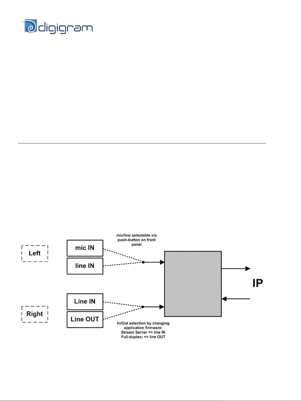
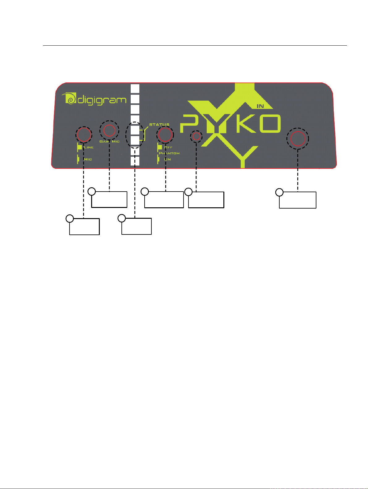
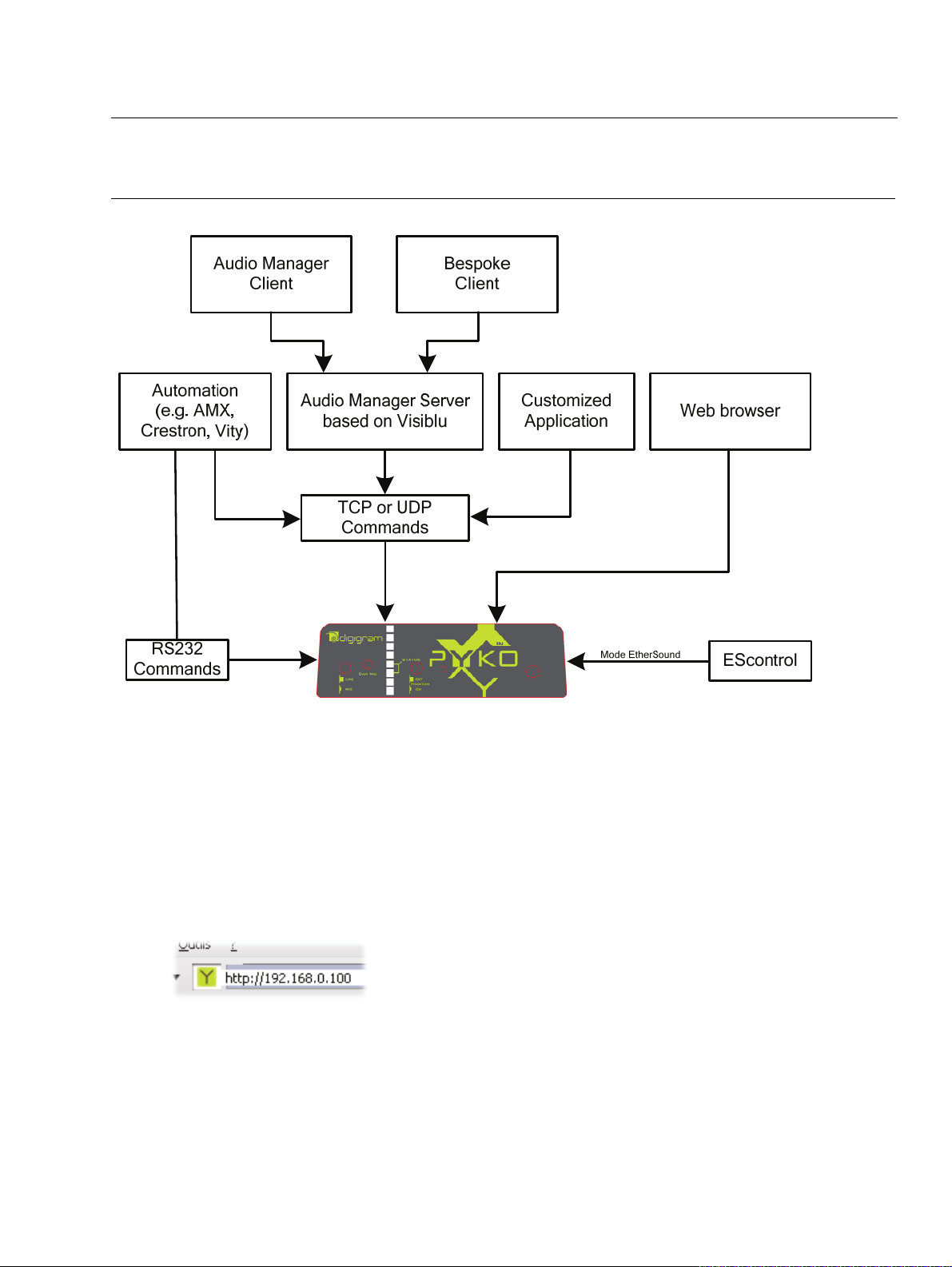
Digigram PYKO-in User manual

t
PYKO-in
Professional IP ÙAudio Endpoint
User manual

PYKO-in
Professional IP
Ù
Audio Endpoint
1
ied personnel only after disconnecting the power
o be connected only to a
ied in this manual
r shock, do not expose this
ure. Do not place objects filled
n of the building should dispose
the legal standards in the country of use is
ocations, or
oist or humid locations.
f this product to an IT power supply system
latile cleaning agent. Do not use abrasive
ther
illed, the apparatus has
in or moisture, does not operate
Before moving the unit, be certain to disconnect any
cables that connect with other components.
par du per
cordon d’ali câbles réseaux !
ée dans ce manuel d´utilisateur et sur
aucune ouverture de ventilation !
e placez pas
sur l’appareil.
accessible et à proximité immédiate de
régime
n IT n’est possible qu’en Norvège.
uis rincez le á l´aide
dommager
étalliques ou d´autres pièces.
n ainsi
que tous les câbles la reliant à d´autres appareils.
n der Strom-
und Netzwer werden.
angegebenen Stromversorgung betrieben
rdecken!
euchtigkeit in Berührung kommen.
e das Gerät auf einen festen,
inen eventuellen Problemfall leicht
e IT-
ur in Norwegen genehmigt.
n, da
uren nur von qualifizierten
so ist es von qualifizierten Fachleuten zu
reparieren.
Important Safety Information
read carefully before using this equipment!
Follow these instructions and keep them in a safe place! Keep in mind that damages due to failure to
observe the instructions contained in this manual are not covered by warranty.
Instructions importantes de sécurité
lire soigneusement avant d’utiliser l’équipement!
Lisez et suivez ces instructions. Conservez les pour consultation ultérieure! Les dommages dus au non-
respect des instructions contenues dans ce manuel ne sont pas couverts par la garantie.
Wichtige Sicherheitshinweise
vor Inbetriebnahme des Gerätes sorgfältig lesen!
Befolgen Sie die Anweisungen und bewahren Sie sie für spätere Fragen auf! Bei Schäden, die durch
Nichtbeachten dieser Bedienungsanleitung verursacht werden, erlischt der Garantieanspruch!
Throughout this manual,
the lightning bolt triangle is
used to alert the user to the
risk of electric shock.
The exclamation point
triangle is used to alert the
user to important operating
or maintenance
instructions.
Do Not Open the Cabinet
There are no user-serviceable components
inside this product. Opening the cabinet
may present a shock hazard, and any
modification to the product will void your warranty. If it
is necessary to open the device for maintenance or
advanced configuration purposes, this is to be done by
qualif
cord and network cables!
Power supply
The device is t
power supply as specif
and marked on the equipment.
ent must be earthed!
This equipm
Do not block any of the ventilation openings!
Humidity
To reduce the risk of fire o
device to rain or moist
with liquid on this device.
Installation Location
To ensure proper operation and to avoid safety hazards,
the device must be installed in a 19“ rack mount chassis.
The electrical installatio
of easily accessible disconnecting means in the immediate
vicinity of the device.
If rack installation is not possible, place it on a firm and
level surface. The use of a supply lead with a power plug
respecting
obligatory. The plug shall be easily accessible in case of a
problem.
Avoid installation in extremely hot or cold l
in an area that is exposed to direct sunlight or heating
equipment. Avoid m
Connection o
is only in Norway.
Cleaning
Clean only with a soft, dry cloth. If necessary, after
disconnecting the unit’s cables, wipe it with a soft cloth
dampened with mild soapy water, then with a fresh cloth
with clean water. Wipe dry immediately with a dry cloth.
NEVER use benzene, aerosol cleaners, thinner, alcohol or
any other vo
cleaners, which may damage the finish of metal or o
parts.
Refer all servicing to qualified service personnel.
Servicing is required when the apparatus has been
damaged in any way, such as power supply cord or plug
is damaged, liquid has been sp
been exposed to ra
normally, or has been dropped.
Moving the device
Ne pas ouvrir l’appareil
L’ouverture du coffret peut produire un
risque de choc électrique, et toute
modification du produit annule votre
garantie. S’il est nécessaire d’ouvrir l’appareil pour
l’entretien ou la configuration avancée, cela doit être fait
sonnel qualifié, après avoir débranché le
mentation et les
Alimentation
Il est primordial de connecter l’appareil à
une alimentation électrique telle que
spécifi
le matériel même.
Cet équipement doit être raccordé à la terre !
N’obstruer
Humidité
Afin de réduire les risques de feu ou de choc, n’exposez
pas cet appareil à la pluie ou l’humidité. N
d´objet contenant un liquide
Installation, mise en place
Afin d’assurer le fonctionnement correct et de minimiser
les risques potentiels liés à la sécurité, l’appareil doit être
installé dans un chassis. Prévoir dans l’installation
électrique du bâtiment un dispositif de sectionnement
aisément
l’appareil.
Si l’installation dans une baie ne vous est pas possible,
placez-le sur une surface solide et plane. L’utilisation
d’un câble d’alimentation avec une fiche de prise de
courant respectant les normes en vigueur dans le pays
d’utilisation est obligatoire. De plus la fiche de prise de
courant doit être aisément accessible en cas de problème.
Évitez une installation dans des endroits très chauds ou
très froids ainsi que dans des lieux exposés directement
au soleil. Évitez les lieux présentant un excès d’humidité.
Le raccordement de ce produit à un
d’alimentatio
Nettoyage
Nettoyez uniquement avec un chiffon doux et sec. Si
nécessaire, après avoir débranché le cordon
d´alimentation, essuyez-le avec un chiffon doux
humidifié avec de l´eau savonneuse p
d un chiffon propre et d´eau claire.
Séchez-le immédiatement avec un chiffon sec. N’utilisez
JAMAIS d´essence, de nettoyants en aérosols, d´alcool ou
tout autre agent nettoyant volatile. N’utilisez pas de
produits nettoyants abrasifs qui pourraient en
les finitions m
Réparation
Lorsque l’appareil a été endommagé quelle qu’en soit la
cause ou qu’il ne fonctionne pas normalement, toute
réparation doit être effectuée par du personnel
qualifié.<0} Avant de transporter l´unité, assurez-vous
d´avoir bien déconnecté le cordon d’alimentatio
Gerät nicht öffnen
Öffnen des Geräts kann eine Gefährdung
durch Stromschlag und Erlöschen der
Garantie zur Folge haben. Reparaturarbeiten
und Änderungen der Hardwarekonfiguration dürfen nur
von qualifiziertem Personal nach entferne
kkabel durchgeführt
Stromversorgung
Das Gerät darf nur mit der in dieser
Bedienungsanleitung und auf dem Gerät
werden.
Erdung ist zu gewährleisten!
Belüftungsschlitze nicht ve
Wasser und Feuchtigkeit
Um Brand- oder Stromschlagrisiken zu vermeiden, darf
das Gerät nicht mit F
Aufbau des Geräts
Um den einwandfreien Betrieb zu gewährleisten und
Sicherheitsrisiken zu vermeiden, sollte das Gerät in
einem 19-Zoll Baugruppenrahmen montiert werden. Die
elektrische Installation des Gebäudes sollte über einen
leicht zugänglichen Trennschalter in unmittelbarer Nähe
des Geräts verfügen Nur wenn die Installation im Rack
nicht möglich ist, stellen Si
waagerechten Untergrund.
Die Verwendung eines Anschlußkabels und eines
Steckers, die die im Benutzungsland gültigen Normen
erfüllen, ist obligatorisch. Des weiteren muß die
Steckdose für e
zugänglich sein.
Meiden Sie Standorte in der Nähe von Wärme- oder
Feuchtigkeitsquellen sowie direkte Sonneneinstrahlung.
Anschluß dieses Produktes an eine speziell
Stromversorgung ist n
Reinigen des Geräts
Säubern Sie das Gerät nur mit einem weichen, trockenen
Tuch. Bei Bedarf verwenden Sie ein mit mildem
Seifenwasser befeuchtetes Tuch, nachdem Sie die
Netzanschlusskabel aus der Steckdose gezogen haben,
anschließend ein weiches, mit klarem Wasser
befeuchtetes Tuch. Trocken Sie das Gerät sofort im
Anschluß. Keinesfalls Benzol, Verdünner oder sonstige
starke Lösungsmittel oder Scheuerreiniger verwende
hierdurch das Gehäuse beschädigt werden könnte.
Lassen Sie etwaige Reparat
Fachleuten durchführen!
Sollten das Netzkabel oder der Netzstecker beschädigt
sein, oder sollte das Gerät selbst beschädigt worden sein
(z. B. durch Eindringen von Feuchtigkeit durch Fall auf
den Boden), oder sollte es nicht ordnungsgemäß
funktionieren oder eine deutliche Funktionsabweichung
aufweisen,

2
TABLE OF CONTENTS
INFORMATION FOR THE USER
.......................................................................................................................................................................................3
CONTENTS OF THIS PACKAGE
........................................................................................................................................................................................3
KEY FEATURES
.................................................................................................................................................................................................................................4
The PYKO-in front panel.................................................................................................................................................................................................................... 5
The PYKO-in back panel.................................................................................................................................................................................................................... 6
INSTALLATION
................................................................................................................................................................................................................................7
Connecting your PYKO-in device ...................................................................................................................................................................................................... 7
Power supply................................................................................................................................................................................................................................. 7
Set-up ............................................................................................................................................................................................................................................. 7
Audio............................................................................................................................................................................................................................................... 7
Configuration......................................................................................................................................................................................................................................... 7
Firmware update.................................................................................................................................................................................................................................. 7
MODES OF OPERATION
...........................................................................................................................................................................................................8
MANAGING PYKO-IN
................................................................................................................................................................................................................9
Configuration......................................................................................................................................................................................................................................... 9
Using PYKO-in with Audio Manager.....................................................................................................................................................................................10
PYKO-in in ‘stand-alone’ mode...............................................................................................................................................................................................10
Audio configuration............................................................................................................................................................................................................................11
With the ‘Stream Server’ firmware ..............................................................................................................................................................................11
With the Full-duplex firmware.......................................................................................................................................................................................12
With the ‘Play-out' firmware ..........................................................................................................................................................................................13
Using PYKO-in with EtherSound ............................................................................................................................................................................................13
GPIO..............................................................................................................................................................................................................................................14
GPI.........................................................................................................................................................................................................................................14
GPO.......................................................................................................................................................................................................................................14
SERIAL PORT (RS232 ON DB9)...........................................................................................................................................................................................14
Audio format...............................................................................................................................................................................................................................14
SPECIFICATIONS
.......................................................................................................................................................................................................................... 15
Configuration.......................................................................................................................................................................................................................................15
Inputs ....................................................................................................................................................................................................................................................15
Outputs.................................................................................................................................................................................................................................................16
Connectivity .........................................................................................................................................................................................................................................16
Software, formats, protocols ...........................................................................................................................................................................................................16
APPENDIX A: FIRMWARE
.................................................................................................................................................................................................. 17
Firmware description.........................................................................................................................................................................................................................17
APPENDIX B: INPUT/OUTPUT LEVEL SELECTION
..................................................................................................................................... 18
Jumper position on motherboard...................................................................................................................................................................................................18
Nominal output level ................................................................................................................................................................................................................19
Nominal input level...................................................................................................................................................................................................................19
APPENDIX C: RTP FORMAT
............................................................................................................................................................................................ 20
RTP frame size ...................................................................................................................................................................................................................................20
RTP payload types .............................................................................................................................................................................................................................20
APPENDIX D: AUDIO CONNECTORS
..................................................................................................................................................................... 21
Pinout ....................................................................................................................................................................................................................................................21
APPENDIX E: GPIO CONNECTORS
........................................................................................................................................................................... 22
GPI pinout ............................................................................................................................................................................................................................................22
GPO pinout..........................................................................................................................................................................................................................................22
General Purpose Inputs (GPIs) .......................................................................................................................................................................................................22
General Purpose Outputs (GPOs)..................................................................................................................................................................................................22
GPO relay specifications...........................................................................................................................................................................................................22
APPENDIX F: SERIAL PORT (RS232 ON DB9)
.............................................................................................................................................. 23
APPENDIX G: MOUNTING PYKO IN A RACK
............................................................................................................................................... 24

PYKO-in
Professional IP
Ù
Audio Endpoint
3
INFORMATION FOR THE USER
This equipment has been tested and found to comply with the limits for a CLASS B digital device, pursuant to Part 15 of the FCC
Rules and with the following European and international Standards for:
In order to guarantee compliance with the above standards in an installation, the following must be done:
·the provided cables must not be modified.
·additional cables used must have their respective shield connected to each extremity.
The limits specified in the standards are designed to provide reasonable protection against harmful interference in a residential
installation. This equipment generates, uses and can radiate radio frequency energy and, if not installed and used in accordance with
the instruction, may cause harmful interference to radio communications. However, there is no guarantee that interference will not
occur in a particular installation.
If this equipment does cause harmful interference to radio or television reception, which can be determined by turning the equipment
off and on, the user is encouraged to try to correct the interference by one or more of the following measures:
* reorient or relocate the receiving antenna.
* increase the separation between the equipment and the receiver.
* connect the equipment into an outlet on a circuit different from that to which the receiver is connected.
* consult the dealer or an experienced audio/television technician for help.
Note:Connecting this device to peripheral devices that do not comply with CLASS B requirements or using an unshielded peripheral data
cable could also result in harmful interference to radio or television reception. The user is cautioned that any changes or modifications
not expressly approved by the party responsible for compliance could void the user’s authority to operate this equipment. To ensure
that the use of this product does not contribute to interference, it is necessary to use shielded I/O cables.
This card has been tested and found to comply with the following standards:
•International: CISPR22 (2005) Class B.
•Europe: EMC 2004/108/CE specifications.
•United States: FCC Rules-Part 15-Class B (digital device).
In order to guarantee compliance with the above standards in an installation, the following must be done:
•the provided cable must not be modified.
•additional cables used must have their respective shield connected to each extremity.
CONTENTS OF THIS PACKAGE
The package consists of the following components:
•a PYKO-in device
•a counterpart for the power connector
Also available (optionally):
•Power supply with cable and connector mounted.
•Adaptor for mounting the PYKO-in on a DIN rail
Copyright 2008 – 2009 Digigram. All rights reserved.
No portion of this manual may be reproduced without prior written consent from Digigram. The copyright protection claimed here includes
photocopying, translation and/or reformatting of the information contained in this manual.
While every effort has been made to ensure accuracy, Digigram is not responsible for errors, omissions or typos and reserves the right to make
improvements or changes in the products and programs described without notice.
Digigram, the Digigram logo, and PYKO are registered trademarks or trademarks of Digigram S.A.. All other trademarks are property of their respective
holders.

4
You have just acquired a Digigram IP Ùaudio bridge and we congratulate
you!
PYKO-in allows you to draw the most from an IP network in order to set up professional audio installations.
Three different firmware applications make PYKO-in a flexible solution that can easily keep up as your
system evolves.
The manual at hand will guide you through installation, configuration and use. For any software related
issue, please refer to the specific documentation provided in its on-line help.
For more information on PYKO applications, please refer to the document ‘Audio system cookbook’,
available on our Web site.
KEY FEATURES
•1 stereo or 1 mono input and one mono output, 1 mic input (see schematic underneath)*
•1 RJ45 port
•1 headphones output
•4/4 GPIOs on terminal block
•1 RS232 port
•1/3“ 1U rack enclosure
•Remote management through .html pages, ‘Audio Manager’ software or ‘EScontrol’ software (in
EtherSound mode)

PYKO-in
Professional IP
Ù
Audio Endpoint
5
The PYKO-in front panel
Mic gain
adjustment
2
Status
LEDs
3
Headphones
out
6
Phantom
Power On/Off
4
Mic/Line
selection
1
Reset
5
1. Mic/line selection
Push-button allowing to switch the input signal between microphone and line.
2. Mic gain setting
Screw allowing to adjust the mic input gain using a flat screwdriver.
3. LEDs
Three electroluminescent diodes indicate the network activity and presence and mode of an audio stream.
•Two electroluminescent diodes labeled ‘STATUS’ indicate the network activity and the presence of an
audio stream.
•A third LED above indicates - when lit - that the audio stream is in full-duplex mode.
4. Phantom power
Push-button allowing to enable/disable 12 V phantom power.
5. Reset button
Press this button briefly to reset your PYKO.
If you press it until the LED blinks (approximately 5 seconds), PYKO is reset to factory configuration, i.e.
to ‘Stream Server’ mode, IP address 192.168.0.100, DHCP=OFF, and the UDP/TCP ports to the default
values 40002 respectively 40004.
6. Headphones out (mini jack)
At start-up, PYKO-in announces its IP address on this output.
•With the ‘Full-duplex’ firmware application, it plays the audio in parallel of line output.
•With the ‘Stream Server’ firmware application, this output is not used.

6
The PYKO-in back panel
1. RJ45 network connector
RJ45 for a network connection in 10/100 Mbps half-/full-duplex.
2. Serial port
RS232 interface on DB9 (see Appendix F, Serial port).
3. GPIO connectors
These terminal blocks allow setup of external control and monitoring devices through configurable and
protected General Purpose Inputs and Outputs (cf. Appendix, management of the GPIOs).
4. Audio connectors
These terminal blocks allow to connect the audio inputs and outputs.
(cf. Appendix D, Audio connectors).
5. Power supply
24 VDC with plug to screw.

PYKO-in
Professional IP
Ù
Audio Endpoint
7
INSTALLATION
Connecting your PYKO-in device
It is recommended to establish all connections before powering the device up.
Power supply
Before plugging the power cord, make sure it is not damaged:
Just like for any other audio system, power the individual devices up following the audio path and power
down in the opposite direction.
Do not allow anything to rest on the power cable. Keep the power cable away from where people could trip
over it.
Set-up
•Use an Ethernet cable to connect your PYKO-in to the network through its RJ45 port (labeled ‘ETH.’
on the back panel). To connect your PYKO-in directly to your computer, use a crossover cable.
•Plug your headphones (front panel)
•Prepare pen and paper in order to write the IP address down, which will be announced over the headphones
output.
•Connect the electric cable to the plug labeled ‘PWR’ on the back panel and to the power outlet
Audio
The pinout used on the XLRs is standard: pin 1 carries the signal ground, pin 2 carries the positive signal
(“hot”, +) and pin 3 carries the negative signal (“cold”, -).
Configuration
You can use PYKO-in along with Audio Manager, in stand-alone or in EtherSound mode.
Firmware update
Digigram provides a firmware (compound.bin) compatible PYKO-in that is installed by default (factory
configuration).
Digigram may decide to publish updates of the embedded firmware. It may then become necessary to upgrade
your devices. In this case, please connect to the corresponding page on www.digigram.com/drivers/index.php
and download the most recent version. Then, go to the <Tools>, <Update> section of the PYKO-in html
page, click ‘Browse’ to indicate the location of the downloaded file, then the ‘Upload’ button. When the
message ‘compound.bin successfully loaded’ is displayed, click onto the link ‘Click on update before
updating the next component or unplug the power supply to reboot the device’ in the message, then
onto the ‘Reboot’ button to finish the update, or, alternatively, disconnect then re-plug the power cord.

8
MODES OF OPERATION
PYKO-in can embed any of the three firmware applications:
•“Stream server”:
•With the ‘Stream Server’ application enabled, PYKO-in reproduces the signal it receives on its
analogical input as one or several IP streams (mono or stereo).<0}
•“Full-duplex”: The ‘Full-duplex’ firmware application (selectable on the html pages) allows managing
the emission of a mono IP stream and the reception of a mono IP stream, thus making it possible to
use an analog mono input and an analog mono output simultaneously, for example for intercom
applications.
•“Play-out”: The Play-out firmware application lets your PYKO-in decode a mono stream. This mode is
rather an ‘emergency’ mode in case you don’t have a PYKO-out at hand. For more detail on this mode,
see the PYKO-out manual.
Particular mode:
•EtherSound: In EtherSound mode, the control of PYKO-in is done through EScontrol. Access to the
web pages is no longer possible.
Note: To return to another mode of operation, please press the ‘Reset’ button > 5 sec in order to re-start
PYKO-in factory configuration. Now you have again access to the embedded html pages were you can
select the required firmware application and configure your PYKO-in.
In factory configuration, PYKO-in is shipped with the ‘Stream Server’ firmware enabled.

PYKO-in
Professional IP
Ù
Audio Endpoint
9
MANAGING PYKO-IN
Depending on your needs, there are several ways of configuring and controlling PYKO-in.
Configuration
PYKO-in embeds a web server that enables you to control the PYKO through your favorite Internet browser
and to select the firmware application that best meets your needs.
•Put your headphones on. At start-up, PYKO will announce its IP address over the headphones output
– write this address down!
Note: PYKO-in factory setting is IP address configured at 192.168.0.100.
•Open your web browser.
•Type the PYKO-in IP address into the address bar and hit the ‘Enter’ key.

10
Using PYKO-in with Audio Manager
If you use your PYKOs with Audio Manager, you will first have to either assign an IP address through the web
pages or turn the DHCP on (Audio Manager will then automatically assign an IP address). Audio Manager
Server will detect this address and allow the Audio Manager Client to configure it.
To be detected by Audio Manager, the TCP control port has to be set to “40002”, the UDP listening port to
“40004”. These are also the values defined in the factory configuration.
Nonetheless, you may decide that Audio Manager is to control PYKO-in only in part. In this case, use the
PYKO-in html pages to configure the device accordingly (cf. on-line help of the pages).
For more details on managing PYKO through Audio Manager, please refer to its on line help.
PYKO-in in ‘stand-alone’ mode
•Select the application firmware that best meets your requirements (see above).
•You can now visualize the Web pages that enable you to parameterize the device.

PYKO-in
Professional IP
Ù
Audio Endpoint
11
Audio configuration
With the ‘Stream Server’ firmware
It is possible to transport an IP stream from a PYKO-in towards different destinations:
•6 in MP3 format
•4 in PCM format
Just configure a destination IP address and a corresponding port for each destination.

12
With the Full-duplex firmware
In full-duplex mode, you will have to configure a mono input and a mono output.
To do so, go to the audio page ‘Audio: Stream priority 2’:
Configure the IP stream to be received (Listening stream) and the IP stream to be sent (Server stream).
PYKO-in is now configured for a full-duplex communication.
In Audio Manager mode, the Audio Manager stream will automatically be set to level 2.
It is also possible to define a priority stream via the page ‘Audio: Stream priority 1’.
A full-duplex communication can then be interrupted by this priority stream for, e.g., an alarm message.

PYKO-in
Professional IP
Ù
Audio Endpoint
13
For more details on parameterizing your PYKO-in in ‘stand-alone’ mode, please refer to on-line help of the
html configuration pages.
With the ‘Play-out' firmware
For the use of PYKO-in ‘Play-out’ mode, please refer to the PYKO-out manual and to the on-line help of the
application firmware. Note, however, that with this firmware, the outputs of a PYKO-in are managed in mono
mode.
Using PYKO-in with EtherSound
PYKO-in is also capable of decoding EtherSound 100/spkr (www.ethersound.com). This is an exclusive mode
of PYKO-in. In this mode, PYKO-in can decode ONE EtherSound mono stream.
As default setting ex factory, the equipment works in IP mode. Switching from IP mode to EtherSound is done
through the Web pages by selecting the EtherSound mode.
In EtherSound mode, the control of PYKO-in is done through EScontrol. Access to the web pages is no longer
possible.
To switch back to IP mode, PYKO-in needs to be reset (press the ‘Reset’ button for at least five seconds).
PYKO-in will re-boot with the default factory settings.
Note: each time PYKO-in is switched from one mode to another, the previous settings are lost, the device reboots in
factory configuration.

14
GPIO
PYKO-in is delivered with four GPIs and four GPOs on terminal block connectors; the counterparts are
provided. For details see Appendix D.
GPI
The PYKO-in GPIs are compatible TTL 5 V.
A GPI must maintain its state for at least 20 ms.
The GPIs can have either local action or a distant action by TCP tunneling.
For the local actions, you can choose:
•Whether it will take place on rising or falling edge
•To start a stream
•To stop a stream
For the TCP tunneling:
•The changes of a GPI state are transmitted through TCP if an application is connected. This
information is received either by Audio Manager or by another application, but it cannot be received
directly by another PYKO-in.
•TCP connection is required by Audio Manager (PYKO-in is used as server). To establish the
connection, the listening port has to be configured by html page.
•The overall latency of the GPI signal transfer via Audio Manager to the destination GPO is inferior to
100 ms.
GPO
The PYKO-in GPOs are relay outputs.
It is possible to configure through the web page whether the value at start-up of each GPO is set to’0’ or to ‘1’.
The GPO can be configured by TCP protocol or from an application.
SERIAL PORT (RS232 ON DB9)
PYKO-in provides an RS232 serial port on a male DB-9 connector on its back panel.
The RS232 can be used to control the PYKO through, e. g. Vity, AMX or Crestron.
It is possible to use the RS232 in gateway mode, in multicast, and in multi-destination (up to 4 destinations)
Parameter setting of the tunneling is done from the PYKO-in html pages.
For the pinout, please refer to the appendix F.
Audio format
PYKO-in can encode and decode various audio formats, depending on the embedded firmware (see
appendix A).

PYKO-in
Professional IP
Ù
Audio Endpoint
15
SPECIFICATIONS
Configuration
Size 140 mm x 41 mm x 145 mm (1/3 1U rack)
Power supply {0><}100{>24 VDC, +/- 20%<0}
WARNING Do not open the power supply module. It contains hazardous voltages. There are no user-
serviceable parts inside.
Temp / humidity
(non-condensing)
Operating:
Storage:
0 °C – 55 °C / 0% - 70%
-5 °C – 70 °C / 0% - 95%
Power requirements at 24 V 0.4 A
Net weight 0,477 kg (∼1.05 lb)
Inputs
Mode Stereo input
(‘Stream Server’) Full-duplex
Analog line inputs 1 stereo 1 mono
Ic input with switchable
12 V phantom power 1 (left) 1 (left)
Maximum input
level/impedance +4 dBu/+18 dBu / >10 kΩ
Frequency response 20 Hz – 20 kHz : 0/-2 dB
THD + noise,
1 kHz at –-1 dBfs 20 Hz – 20 kHz : <-84 dB
Signal to noise ratio 20 Hz – 20 kHz : <-98 dB
Adjustable mic gain 0 - 39 dB
Maximum mic input
level/impedance -2dBu / >10 kΩ
Equivalent Input Noise,
A/D-D/A at 48kHz,
G=39 dB, Z=200 Ω
<-115 dBm

16
Outputs
Mode Stereo input
(‘Stream Server’) Full-duplex
Analog line outputs - 1 mono
Maximum output
level/impedance +4 dBu/+18 dBu / <100 Ω
Frequency response 20 Hz – 20 kHz : 0/-2 dB
THD + noise,
1 kHz at –-2 dBfs 20 Hz – 20 kHz : <-84 dB
Signal to noise ratio 20 Hz – 20 kHz : <-98 dB
Headphones out 1 on Jack (3,5 mm)
Connectivity
Audio 2x3 pins on terminal block
Ethernet port RJ45 10/100-bit.
GPIO 4 GPIs compatible TTL
4 relay GPOs
2x8 pins on terminal block
Serial port 1 RS232 on DB9
Software, formats, protocols
Stream format IP (RTP, SHOUTcast, IceCast)∗
Audio formats
mp3 (variable bit rate up to 192 kBit/s)
G.711 (μLaw/aLaw at 8 kHz)
PCM (16 bit at 8 up to 48 kHz)
Network protocols
Audio-Manager, html pages via embedded web server
http web server: personalized web interface for a flexible management
TCP/UDP commands to enable PYKO management over the network
SNMP: enables PYKO to be managed over the network in very large systems
DHCP, DNS, IGMP
∗en fonction du micrologiciel (firmware) utilisé

PYKO-in
Professional IP
Ù
Audio Endpoint
17
APPENDIX A: FIRMWARE
Digigram provides two PYKO-in compatible applications in one and the same firmwre (compound.bin).
‘Stream Server’ and ‘Full-duplex’.
Firmware description
Firmware Stream server Full-duplex
Audio 1 stereo input 1 mono input and 1 mono output
Management through Audio
Manager • •
Audio formats
MP3
16 to 48 kHz on RTP Encoding Decoding for stream priority 1
PCM (16bit)
8 to 32 kHz on RTP Encoding Encoding/decoding up to 24 kHz
PCM (16bit)
44,1 to 48 kHz on RTP Encoding Decoding for stream priority 1
G711 on RTP Encoding Encoding/decoding
Shoutcast/Icecast
EtherSound Firmware independent / Exclusively mono
GPI management • •
GPO management • •
FD Serial Link management
(RS232) • •
Multicast Tx Tx/Rx
IGMP • •
SNMP • •
Priority levels 2

18
APPENDIX B: INPUT/OUTPUT LEVEL SELECTION
These settings shall be executed by qualified personnel only!
Tools required:
•a #1 Pozidriv screwdriver
•an ESD-preventive wrist strap
Electrostatic discharge (ESD) can damage several components on the board. To avoid such damage in
handling the board, take the following precautions:
Bring the device and everything that contacts it to ground potential by providing a conductive surface and
discharge paths. As a minimum, observe these precautions:
•Disconnect all power and signal sources.
•Place the device on a grounded conductive work surface.
•Ground yourself via a grounding wrist strap or by holding a grounded object.
•Ground any tools that will contact the device.
•Unscrew the two Pozidriv screws counterclockwise
and open the cabinet.
Jumper position on motherboard

PYKO-in
Professional IP
Ù
Audio Endpoint
19
Nominal output level
Jumper positioning
This setting defines whether the nominal level of the analog signals is either +18 dBu or +4 dBu (Professional
nominal level).
Default factory setting is +18 dBu.
The settings described above act upon the nominal output level. Having located the pair to modify in the
overview picture, set the jumpers according to the above illustrations to match the requirements of your
system.
Nominal input level
Jumper positioning
This setting defines whether the nominal level of the analog signals is either +18 dBu or +4 dBu (Professional
nominal level).
Default factory setting is +18 dBu for both inputs.
The settings described above act upon the nominal input level. Having located the pair to modify in the
overview picture, set the jumpers according to the above illustrations to match the requirements of your
system.
Other manuals for PYKO-in
2
Table of contents
Other Digigram Media Converter manuals

Digigram
Digigram EtherSound ES881v2 User manual

Digigram
Digigram PYKO-in User manual

Digigram
Digigram PYKO-out User manual

Digigram
Digigram aqord *link User manual

Digigram
Digigram PYKO-out User manual

Digigram
Digigram Aqonda 8 User manual

Digigram
Digigram PYKO-in User manual

Digigram
Digigram EtherSound ES220 User manual

Digigram
Digigram IQOYA *LINK User manual

Digigram
Digigram EtherSound ES8in User manual