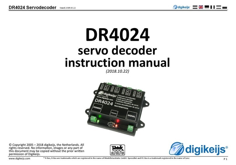
Digikeijs DR4024 User manual

© Copyright 2005 – 2021 Digikeijs, the Netherlands. All
rights reserved. No informaon, images or any part of
this document may be copied without the prior wrien
permission of Digikeijs.
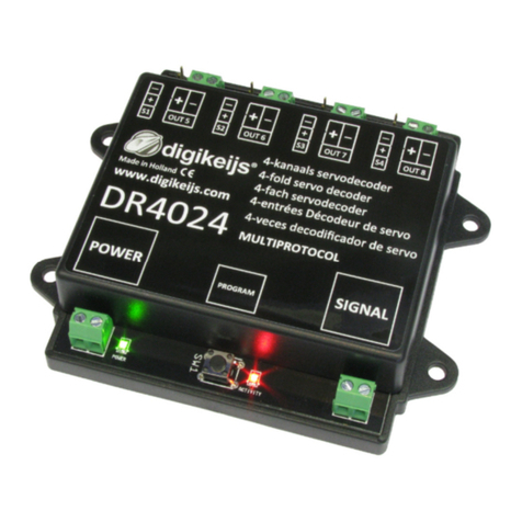
DR4024 servo decoder
*R-Bus, B-Bus are registered trademarks of Modelleisenbhan GmbH. XpressNet and RS-Bus are registered trademarks of Lenz
www.digikeijs.com 1
DR4024
servo decoder
Instruction manual

1 Index 2
1.0 General informaon 2
1.1 Index 2
1.2 Warranty and warranty condions 3
1.3 Legal informaon 3
2.0 Product overview 4
2.1 General product informaon 4
2.2 Technical Specicaons 4
2.3 Hardware Overview 5
3.0 Programming 6
3.1 Programming the magnec arcle address 7
3.2 Programming the servo posions A-D 8
3.3 Programming CV's via POM
(main track programming) 9
3.4 Programming CVs on the Programming Track 10
3.5 Reseng the DR4024 to Factory Defaults
(main track POM programming) 11
3.6 Reseng the DR4024 to Factory Defaults
(programming track) 12
3.7 Special feature CV programming for control panels
which switch o the programming track 13
3.8 Reseng the DR4024 to factory sengs for
Control panels which switch o the
programming track 14
4.0 Troubleshoong, 15
4.1 The red LED goes out again even though the
programming buon was not pressed again. 15
5.0 Connecon examples 16
5.1 Connecon opons Power and
Signal Connecon 16
5.2 Connecon DR4102 relay switch polarizaon 17
5.3 Enclosed level crossing with asher 18
5.4 Wing signal NL 18
1 General Informaon
6.0 Servo installaon and connecon 19
7.0 CV Table 20
7.1 Funcon mapping 23
7.2 Presets 24
Please note!
This manual contains currently only the basic information and will be extended
step by step. Suggestions, improvements, additions, comments or suggestions
are always welcome.
DR4024 servo decoder
*R-Bus, B-Bus are registered trademarks of Modelleisenbhan GmbH. XpressNet and RS-Bus are registered trademarks of Lenz
www.digikeijs.com 2

1.2 Warranty and warranty condions
All our products have a 24-month manufacturer's warranty. Read these operang instrucons carefully.
Damage to the product caused by non-compliance with these instrucons will void the warranty.
ATTENTION: The warranty is void if the housing of the product is opened.
1.3 Legal informaon
Prinng errors and mistakes, technical or other changes as well as changes in the availability of individual products are expressly reserved.
Data and illustraons are non-binding. All changes to hardware, rmware and soware are reserved.
We reserve the right to change the design of the product, soware and/or rmware without prior noce.
Copyright
All Digikeijs manuals and other wrien instrucons that are supplied and/or downloaded are protected by copyright.
Duplicaon is not permied without wrien permission from Digikeijs.
DR4024 servo decoder
*R-Bus, B-Bus are registered trademarks of Modelleisenbhan GmbH. XpressNet and RS-Bus are registered trademarks of Lenz
www.digikeijs.com 3

2.0 Product overview
2.1 General product informaon
The DR4024 is a mulprotocol decoder that automacally detects DCC and MM.
With the funcon mapping via CV programming it is possible to realize all imaginable tasks. The DR4024 is a servo decoder with four servo outputs.
Each servo output can be programmed to move to four dierent posions. The DR4024 also has four addional switching outputs which can be used, for exam-
ple, for switch polarizaon or for controlling St. Andrew's crosses and much more.
The DR4024 switches o the control of the servos when the posion is reached, thus guaranteeing that no unnecessary power is consumed.
2.2 Technical specicaons
The connecon terminals for power and signal (track voltage) are designed for a cross-secon of 0.5mm².
Number of
Outputs
Protokoll Loading Capacity
Out 5 - Out 8
Load capacity of the
servo outputs
power supply voltage
DR4024 4 x Servo
(S1-S4)
4x switching output
(Out 5 - Out 8)
DCC
MM
2 A Per output max 1A
(When operang several servos si-
multaneously S1 and S2 total 1A
or S3 and S4 total 1A)
12-18V DC
Minimum recommendaon 12V DC 2A
12-18V AC
Note on power supply:
When using "old" transformers (AC output), under certain circumstances there may be malfuncons in the operaon of the servos.
For this reason we generally recommend the use of switching power supplies with at least 12V (DC) output voltage (DC voltage) and 2A output power.
DR4024 servo decoder
*R-Bus, B-Bus are registered trademarks of Modelleisenbhan GmbH. XpressNet and RS-Bus are registered trademarks of Lenz
www.digikeijs.com 4

2.3 Hardware Overview
1Connecon S1 Servo 1 (Output 1)
2Connecon Out 5 (Output 5)
3Connecon S2 Servo 2 (Output 2)
4Connecon Out 6 (Output 6)
5Connecon S3 Servo 3 (Output 3)
6Connecon Out 7 (Output 7)
7Connecon S4 Servo 4 (Output 4)
8Connecon Out 8 (Output 8)
9Power Anschluss
10 Green LED
Display Supply voltage present
11 programming buon
12 Red LED
Display programming mode
(glows constantly)
Display switching command is executed
(lights up as long as movement is in progress)
13 Signal (rail connecon)
12345678
910 11 12 13
DR4024 servo decoder
*R-Bus, B-Bus are registered trademarks of Modelleisenbhan GmbH. XpressNet and RS-Bus are registered trademarks of Lenz
www.digikeijs.com 5

3.0 Programming
If the power input and the signal input of the DR4024 are connected to each other and are connected to the siding of the control unit, the control unit may
shut down due to overload.
It is beer to use a switching power supply (DC) with at least 12V 2A for adjustment work and normal operaon. You should always keep in mind that some
servos have a "high" current requirement, which can lead to the central unit being switched o during operaon or seng.
Basic informaon about programming the DR4024.
Please pay aenon to these points as otherwise the programming may fail or errors may occur.
• CV programming is always possible on the programming track (if available).
• Some command staons switch o the programming track, which makes programming the DR4024 on the programming track somewhat more
dicult.
• With some central units it comes with the readout of CV's at the programming track again and again to problems that the max. current at the pro-
gramming track, which is available, is too small. Then disconnect the connected servos from the DRR4024.
• To read CV's on the programming track, the connecons POWER and SIGNAl must be connected to the programming track of the central unit.
• Please disconnect the external power supply at the DR4024.
• POM programming is always possible on the main track.
• CV readout via POM or Railcom® is not possible.
DR4024 servo decoder
*R-Bus, B-Bus are registered trademarks of Modelleisenbhan GmbH. XpressNet and RS-Bus are registered trademarks of Lenz
www.digikeijs.com 6

Supply voltage
12-18V DC/AC
3.1 Programming the turnout address
The turnout addresses are always assigned by a turnout command!!!
Make sure the DR4024 is powered from the decoder's power connector. It is best to use a switching power supply with at least 12V DC output voltage
and 2A output power. The signal connecon of the decoder must be connected to the main track output of your control panel!
1. Call up the desired magnec arcle address which the DR4024 is to receive as the start address at the central unit, handset controller, app, etc.
2. Press the programming buon on the DR4024, the red LED will light up connuously.
The decoder is now in programming mode.
3. The next step is to switch the desired turnout address with the control panel, the app or the handset control.
DR4024 as the start address.
4. The programming mode is automacally terminated aer switching the turnout address.
The red LED goes out again to indicate that the programming mode has been exited.
5. The DR4024 now occupies a maximum of 8 addresses starng with the rst switched turnout address.
The start address (turnout address) for the DR4024 is always assigned via a turnout command and not via the CV1!!!
If the CV1 is nevertheless wrien with an address, the decoder can no longer be programmed with the locomove address 9999!
DR4024 servo decoder
*R-Bus, B-Bus are registered trademarks of Modelleisenbhan GmbH. XpressNet and RS-Bus are registered trademarks of Lenz
www.digikeijs.com 7

1. Make sure the DR4024 is powered from the decoder's power connector. It is best to use a switching power supply with at least 12V DC output voltage and 2A output power.
The signal connector of the DR4024 must be connected to the main track output of your control panel!
2. A locomove with address 9999 and 128 speed steps DCC must be dened in the central unit, mul mouse, app etc..
This locomove address can be used to control and program the DR4024 like a locomove.
3. Select the locomove with the address 9999 at the central staon, mul mouse, app, etc.
Switch funcon F0 on and o again to acvate the locomove in the control center.
If this procedure is not carried out, some command staons do not recognize that the locomove 9999 has been called. Then it is not possible to carry out the following pro-
gramming!
4. Make sure that the funcons F0 (light), F1, F2, F3 and F4 are switched o on the control panel, App or on the handset control.
Set the speed control knob at the control panel, app or handset to zero speed.
5. Now actuate the servo that you want to set (via the control panel by means of the switch address).
The selected servo will now move to the switched posion.
6. Press the programming buon on the DR4024. The red LED now lights up connuously and indicates that the DR4024 is in "Programming Mode" is located. The servo just
actuated now moves to the neutral posion (centre posion of the servo).
7. Move the speed controller (forwards or backwards) and set the servo to the desired posion A (le posion A).
8. Switch the F1 funcon on the speed controller on and o again to save this posion A in the DR4024.
Important: when saving the posions in the decoder, the red LED goes out briey to indicate that the posion has been saved.
9. Turn the speed controller (forwards or backwards) and set the servo to the desired posion B (right posion B).
10. Switch funcon F2 on the speed controller on and o again to save this posion B in the DR4024.
11. If you only want to change or set posions A and B, proceed to step 16.
12. Turn the speed controller (forwards or backwards) and set the servo to the desired posion C (le posion C).
13. Switch the funcon F3 on the speed controller on and o again to save this posion C in the DR4024.
14. Turn the speed controller (forwards or backwards) and set the servo to the desired posion D (right posion D).
15. Switch the funcon F4 on the speed controller on and o again to save this posion D in the DR4024.
16. Press the programming buon on the DR4024 decoder to exit programming mode.
The red LED now goes out and indicates that the programming mode has been exited.
17. Repeat the above steps for each servo output to adjust.
A
C
B
D
Instead of ending the programming mode with step 16 you can select the next servo by switching F0 on and o (switching the light on and o
again) and connue with step 7 to program the next servo at the decoder.
DR4024 servo decoder
*R-Bus, B-Bus are registered trademarks of Modelleisenbhan GmbH. XpressNet and RS-Bus are registered trademarks of Lenz
www.digikeijs.com 8
3.2 Programming the servo posions A-D

3.3 Programming of CV's via POM (main track programming)
Make sure the DR4024 is powered from the decoder's power connector. The green LED next to the power connector must now light up permanently. It is best
to use a switching power supply with at least 12V DC output voltage and 3A output power. The signal connecon of the decoder must be connected to the main
track output of your control panel! The DR4024 cannot be read out via Railcom®!
1. A locomove with address 9999 and 128 speed steps DCC must be dened in the central unit, mul mouse, app etc..
The DR4024 can be programmed similar to a locomove decoder using this locomove address.
2. Select the locomove with the address 9999 at the central staon, mul mouse, app, etc.
Switch the funcon F0 (light) on and o again to acvate the locomove in the control panel.
3. Press the programming buon on the DR4024. The red LED is now lit connuously and indicates that the DR4024 is in "programming mode".
4. Select the CV Programming (POM) funcon in your control panel, app or handset.
(For further informaon on CV byte or CV bit programming, please refer to the operang instrucons of your control panel)
5. Now the desired CV value can be wrien to the DR4024 with the respecve funcon Write POM of the central, app or handset controller.
6. An innite number of CV's can be sent one aer the other to the DR4024.
7. To exit the programming mode of the DR4024, the programming buon must be pressed again.
The red LED goes out and indicates that the programming mode has been terminated.
Supply voltage
12-18V DC/AC
The start address (turnout address) for the DR4024 is always assigned via a turnout command and not via the CV1!!!
If the CV1 is nevertheless wrien with an address, the decoder can no longer be programmed with the locomove address 9999!
Aenon!!! If for any reason the address 9999 required for
programming has been changed in the DR4024, the reset must
be carried out via the programming track, point 3.6.
DR4024 servo decoder
*R-Bus, B-Bus are registered trademarks of Modelleisenbhan GmbH. XpressNet and RS-Bus are registered trademarks of Lenz
www.digikeijs.com 9

3.4 Programming of CV's via the programming track
Connect the signal and power connecons of the DR4024 to the programming track connecon of your control panel.
Please note that reading out and programming the DR4024 via the programming track only works if the central unit does not switch o the programming track!
Therefore, before aempng programming, check that the green LED next to the power connector is lit. Only if this is the case can the DR4024 be successfully
programmed as described in this secon. If the green LED does not light up, refer to secon 3.6 of this manual.
1. Connect the signal and power connecons to the programming track of the control panel.
2. Now check whether the green LED next to the power connector is permanently lit.
If the green LED does not light up, refer to secon 3.6 of this manual.
3. A locomove with address 9999 and 128 speed steps DCC must be dened in the central unit, mul mouse, app etc..
The DR4024 can be programmed similar to a locomove decoder using this locomove address.
4. Select the locomove with the address 9999 at the central staon, mul mouse, app, etc.
Switch the funcon F0 (light) on and o again to acvate the locomove in the control panel.
5. Press the programming buon on the DR4024. The red LED is now lit connuously and indicates that the DR4024 is in "programming mode".
6. Select the CV programming funcon via the programming track in your central, app or handset controller.
(For further informaon on CV byte or CV bit programming, please refer to the operang instrucons of your control panel)
The start address (turnout address) for the DR4024 is always assigned via a turnout
command and not via the CV1!!!
If the CV1 is nevertheless wrien with an address, the decoder can no longer be pro-
grammed with the locomove address 9999!
DR4024 servo decoder
*R-Bus, B-Bus are registered trademarks of Modelleisenbhan GmbH. XpressNet and RS-Bus are registered trademarks of Lenz
www.digikeijs.com 10

3.5 Reset DR4024 to Factory Sengs(Main Track POM programming)
Connect the signal and power connectors of the DR4024 to the main track connector of your control panel. The green LED next to the power connector must
now light up permanently. Alternavely, the power connecon can also be supplied with an external power supply (min 12V DC 2A).
The DR4024 cannot be read out via Railcom®!
1. A locomove with address 9999 and 128 speed steps DCC must be dened in the central unit, mul mouse, app etc.
The DR4024 can be programmed similar to a locomove decoder using this locomove address.
2. Select the locomove with the address 9999 at the central staon, mul mouse, app, etc.
Switch the funcon F0 (light) on and o again to acvate the locomove in the control panel.
3. Press the programming buon on the DR4024. The red LED now lights up connuously and indicates that the DR4024 is in "programming mode".
is located.
4. Select the CV Programming (POM) funcon in your control panel, app or handset.
(For further informaon on CV byte or CV bit programming, please refer to the operang instrucons of your control panel)
5. Now write the CV 8 with the decimal value 8 to reset the DR4024.
6. Exit the programming mode by pressing the programming buon on the DR4024.
The red LED goes out and indicates that the programming mode has been terminated.
Important! Otherwise the DR4024 starts in programming mode again.
7. Now disconnect the power and signal connecons from the main track
Aenon! Wait approx. 30 seconds before powering the DR4024 again and restoring the siding.
Supply voltage
12-18V DC/AC
The start address (turnout address) for the DR4024 is always
assigned via a turnout command and not via the CV1!!!
If the CV1 is nevertheless wrien with an address, the de-
coder can no longer be programmed with the locomove
address 9999!
DR4024 servo decoder
*R-Bus, B-Bus are registered trademarks of Modelleisenbhan GmbH. XpressNet and RS-Bus are registered trademarks of Lenz
www.digikeijs.com 11

3.6 Reset DR4024 to Factory Sengs (Programming Track)
The reset via the programming track should only be done if the reset via the POM programming did not work.
Connect the signal and power connecons of the DR4024 to the programming track connecon of your control panel.
Please note that reading out and programming the DR4024 via the programming track only works if the central unit does not switch o the programming track! Therefore,
before aempng programming, check that the green LED next to the power connector is lit. Only if this is the case can the DR4024 be successfully programmed as de-
scribed in this secon. If the green LED does not light up, refer to secon 3.7 of this manual.
1. Connect the signal and power connecons to the programming track of the control panel.
2. Now check whether the green LED next to the power connector is permanently lit.
If the green LED does not light up, refer to secon 3.7 of this manual.
3. Press the programming buon on the DR4024. The red LED now lights up connuously and indicates that the DR4024 is in "programming mode".
is located.
4. Select the CV programming funcon via the programming track in your central, app or handset controller.
(For further informaon on CV byte or CV bit programming, please refer to the operang instrucons of your control panel)
5. Now write the CV 8 with the decimal value 8 to reset the DR4024.
6. Exit the programming mode by pressing the programming buon on the DR4024.
The red LED goes out and indicates that the programming mode has been terminated.
Important! Otherwise the DR4024 will restart in programming mode.
7. Now disconnect the power and signal connecons from the programming track.
Aenon! Wait approx. 30 seconds before powering the DR4024 again and restoring the siding.
The DR4024 is now reset to factory sengs. The POM address was reset to 9999
again and the DR4024 has the magnec arcle address 1 again. By switching the
magnec arcle address 1 it can be checked whether the RESET was successful.
DR4024 servo decoder
*R-Bus, B-Bus are registered trademarks of Modelleisenbhan GmbH. XpressNet and RS-Bus are registered trademarks of Lenz
www.digikeijs.com 12

3.7 Special feature CV programming for control panels that
Switch o the programming track
Some control panels (Uhlenbrock® Basis®, Daisy 2® Startset, Piko® SmartControl® light, etc.) only switch on the supply voltage to the programming track
during programming. The green LED next to the power connector of the DR4024 indicates whether the programming track always outputs voltage. If this
does not light up connuously, the programming track is switched o. This leads to the DR4024 requiring a dierent programming or reseng procedure
than usual.
This procedure is described in this secon.
1. Now that you have determined that the green LED next to the power connector is not permanently lit, disconnect the POWER and SIGNAL connectors
from the programming track.
2. Connect the POWER and SIGNAL connectors to the main track of your control panel.
Now the green LED next to the POWER connector should light up permanently.
3. Now press the programming buon on the DR4024.
The red LED will light to indicate that the DR4024 is in programming mode
4. Now disconnect the POWER and SIGNAL connectors from the main track (Track Out).
5. Now reconnect the POWER and SIGNAL connecons to the programming track of your control panel.
The green and red LEDs now go out because the programming track is not constantly supplied with power.
The programming mode of the DR4024 remains unchanged.
6. Select the CV programming funcon via the programming track in your central, app or handset controller and program the desired CVs one aer the oth-
er.
(Further informaon on CV byte or CV bit programming can be found in the operang manual of your control panel)
Aer you have successfully changed all desired CV's, you must exit the programming mode of the central unit before proceeding with the next step.
7. Disconnect the POWER and SIGNAL connecons from the programming track.
8. Connect the POWER and SIGNAL connectors to the main track of your control panel.
Now the green LED next to the POWER connector and the red LED both light up again.
The red LED indicates that the DR4024 is sll in programming mode.
9. Now press the programming buons on the DR4024. The red LED goes out and the programming mode is terminated.
DR4024 servo decoder
*R-Bus, B-Bus are registered trademarks of Modelleisenbhan GmbH. XpressNet and RS-Bus are registered trademarks of Lenz
www.digikeijs.com 13

3.8 Reset DR4024 to factory sengs for control units that switch o the programming track
Some control panels (Uhlenbrock® Basis®, Daisy 2® Startset, Piko® SmartControl® light, etc.) only switch on the supply voltage to the programming track
during programming. The green LED next to the power connector of the DR4024 indicates whether the programming track always outputs voltage. If this
does not light up connuously, the programming track is switched o. This leads to the DR4024 requiring a dierent programming or reseng procedure
than usual. This procedure is described in this secon.
1. Now that you have determined that the green LED next to the power connector is not permanently lit, disconnect the POWER and SIGNAL connectors
from the programming track.
2. Connect the POWER and SIGNAL connectors to the main track of your control panel.
Now the green LED next to the POWER connector should light up permanently.
3. Now press the programming buon on the DR4024.
The red LED will light to indicate that the DR4024 is in programming mode.
4. Now disconnect the POWER and SIGNAL connectors from the main track (Track Out).
5. Now reconnect the POWER and SIGNAL connecons to the programming track of your control panel.
The green and red LEDs now go out because the programming track is not constantly supplied with power.
The programming mode of the DR4024 remains unchanged.
6. Select the CV programming funcon via the programming track in your central, app or handset controller.
(Further informaon on CV byte or CV bit programming can be found in the operang manual of your control panel)
To reset to factory sengs, the decimal value 8 must be wrien to CV8.
Aer you have described the CV 8, you must exit the programming mode of the central unit before proceeding with the next step.
7. Disconnect the POWER and SIGNAL connecons from the programming track.
8. Connect the POWER and SIGNAL connectors to the main track of your control panel.
Now the green LED next to the POWER connector and the red LED both light up again.
The red LED indicates that the DR4024 is sll in programming mode.
9. Now press the programming buons on the DR4024. The red LED goes out and the programming mode is terminated.
10. Aenon! Now disconnect the POWER and SIGNAL connecons from the main track of the control panel.
This is absolutely necessary to successfully complete the RESET. Aer approx. 30 seconds the desired connecon can be restored.
The DR4024 is now reset to factory sengs. The POM address was reset to 9999 again and the DR4024 has the magnec arcle address 1 again. By switch-
ing the magnec arcle address 1 it can be checked whether the RESET was successful.
DR4024 servo decoder
*R-Bus, B-Bus are registered trademarks of Modelleisenbhan GmbH. XpressNet and RS-Bus are registered trademarks of Lenz
www.digikeijs.com 14

4.0 Troubleshoong
4.1 The red LED goes out again although the programming buon has not been pressed again.
Some central units have the problem that aer pressing the programming buon of the DR4024, the red LED goes out again shortly aer the programming
mode has been acvated and the DR4024 automacally terminates the programming mode.
This happens if the locomove with the address 9999 has not yet been acvated in the central staon. This can be easily avoided by always "acvang" "the
locomove" with the address 9999 before pressing the programming buon of the DR4024.
In order to avoid the red LED exnguishing, please observe the following procedure for POM programming:
1. Dene a locomove with locomove address 9999 (DCC, 128 speed steps) in the central/mul mouse or app.
2. Acvate the "locomove" with address 9999 in the control panel by switching the lighng on and o again (F0) .
3. Press the programming buon on the DR4024 only now. The red LED will now glow connuously to indicate that the DR4024 is in the
programming mode.
4. Now start to change the desired CV's via POM (locomove address 9999).
5. To exit the programming mode of the DR4024, the programming buon must be pressed again.
The red LED goes out and indicates that the programming mode has been terminated.
DR4024 servo decoder
*R-Bus, B-Bus are registered trademarks of Modelleisenbhan GmbH. XpressNet and RS-Bus are registered trademarks of Lenz
www.digikeijs.com 15

Supply voltage
12-18V DC/AC
Recommended min.
12V DC 2A
5.1 Connecon opons Power and signal Connecon
Signal Connecon to main track
Power Connecon to an external power supply
Recommended for normal operaon and for the POM
programming
Signal Connecon to programming track
Power Connecon to programming track
Signal Connecon to main track
Power Connecon to main track
Alternave to connecng an external power supply.
Suitable for normal operaon and for the POM
programming
5.0 Connecon examples
DR4024 servo decoder
*R-Bus, B-Bus are registered trademarks of Modelleisenbhan GmbH. XpressNet and RS-Bus are registered trademarks of Lenz
www.digikeijs.com 16

DR4024 PRESET 1
+ DC
+
-
Important! Be sure to observe the polarity (+ and - ) of the
DR4102!
An incorrect connecon will destroy the Out x switching output
on the DR4024!
NO
C
5.2 Connecon DR4102 relay switch polarizaon
DR4024 servo decoder
*R-Bus, B-Bus are registered trademarks of Modelleisenbhan GmbH. XpressNet and RS-Bus are registered trademarks of Lenz
www.digikeijs.com 17

5.3 Railway crossing with barrier and interchangeable indicators
5.4 Wing signal NL
DR4024 servo decoder
*R-Bus, B-Bus are registered trademarks of Modelleisenbhan GmbH. XpressNet and RS-Bus are registered trademarks of Lenz
www.digikeijs.com 18

6.0 Servo installaon and connecon
• Servo connecon cables should always be kept as short as possible to avoid interference.
• With long servo cables, always use twisted connecon cables with a cross-secon of at least 0.35 mm² to minimize interference.
• Always lay the servo cables separately from other cables to avoid interference.
• Always make sure that the voltage source used can provide sucient current (A).
A switching power supply is beer suited for this purpose than an "old" AC transformer.
• Never twist the servo by hand. This can cause damage to the gearbox of the servo.
• The servo lever should always be mounted in the middle posion of the servo. Observe point 3.2 of this manual.
• Always ensure that the servo has sucient freedom of movement during installaon to avoid damage.
• When screwing on the servo lever, make sure that the servo is not twisted to avoid damage to the gear unit.
• When adjusng the servo posions, ensure that the actuang parts have sucient freedom of movement to avoid damage.
DR4024 servo decoder
*R-Bus, B-Bus are registered trademarks of Modelleisenbhan GmbH. XpressNet and RS-Bus are registered trademarks of Lenz
www.digikeijs.com 19

7.0 CV Table
CV CV Denion Range Value
7Decoder Version 13
8Manufacturer ID Value '8' resets the decoder to factory sengs. 42
17 Long address high byte 192-255 231
18 Long address low byte 0-255 15
47 Presets / Presets 0-3
(this CV can only be wrien a read out is not possible!)
0 – 3 0
The DR4024 servo decoder has four presets to make programming easier. Each preset congures the DR4020 so that you do not have
to change CVs manually. For detailed informaon on these presets, see page 24.
112 Flashing frequency for the switching outputs
with bit 7 acve in CV117 - CV120. Value 20 is 90x per minute.
0-255 20
113
-
116
CVs 113-116 have the same funcon as servos 1-4. 0-255 2
Value Funkon
0Default seng 0 > 4 servos (1-4) and 4 separate switching outputs (5-8) (8 addresses)
1Default seng 1 > 4 servos (1-4) with linked switching outputs (1-4) (4 addresses)
2Default seng 2 > 4 servos with mass simulaon (1-4) and 4 separate switching outputs (5-8) (8 addresses)
3Default seng 3 > Level crossing with asher, 2 barriers and mass simulaon (2 addresses)
Bit Funkon Value
0-3Sets the servo step size.
Value 15 is the fastest;
Value 0 is the slowest.
2
0-15
4-7Sets the servo step speed.
Value 15 is the smallest and Value 0 is the largest. 0 stands for 50 steps per
second. 1 = 25/s, 2 = 12/s, 3 = 5/s, 4 = 4/s. etch... MaximumValue 15 = 1
step / second.
The last seng in combinaon with bits 0-3 switched to 0 means that the
servo switches between the two extreme posions in 126 seconds!
0
(0-15)
*16
DR4024 servo decoder
*R-Bus, B-Bus are registered trademarks of Modelleisenbhan GmbH. XpressNet and RS-Bus are registered trademarks of Lenz
www.digikeijs.com 20
Other manuals for DR4024
2
Table of contents
Other Digikeijs Media Converter manuals
