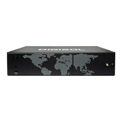
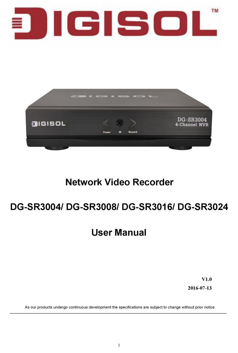
Digisol DG-SR3004 User manual

1
NVR SERIES
4/8/16/24 - Channel
Network Video Recorder
DG-SR3004 / DG-SR3008 / DG-SR3016
DG-SR3024
V1.0
2016-07-20

2
Copyright
Copyright 2016 by Smartlink Network Systems Ltd. All rights reserved.
Company has an ongoing policy of upgrading its products and it may be possible that
information in this document is not up-to-date.
Please check with your local distributors for latest information.
No part of this document can be copied or reproduced in any form without written
consent from the company.
Trademark
DIGISOLTM is a trademark of Smartlink Network Systems Ltd. All other trademarks
are the property of the respective manufacturers.

3
Package Contents
The following items should be present in your package:
1 No. NVR (4/8/16/24 channel)
Power adapter
Quick Installation Guide
1 USB Mouse
Installation Guide CD
Tools package (Screws)
Make sure that the package contains above items. If any of the listed items is damaged
or missing, please contact your retailer immediately.
Product Overview
Thank you for purchasing DIGISOL Network Video Recorder!
This QIG is a reference guide for the installation and operation of your NVR. Before
installation and operation please read the safeguards and warnings mentioned in the
sections below carefully.
Product Features
Provides H.264 high efficiency video Compression.
Supports 4/8/16/24 CH.
Supports Recording / Playback.
Supports up to 4TB HDD.
Supports two USB 2.0 ports for USB mouse.
Provides HDMI/VGA Output.
1 x RJ45 Ethernet LAN.
Supports 1 SATA port (4/8/16 channel) and 2 SATA ports on 24ch NVR.

4
System Requirements
The following system requirements are recommended:
Windows XP, Vista or Win 7 operating system (both 32 or 64 bits version)
4GB of system memory
2GB of Display card memory
100GB of available hard disk space on system drive
At least one SATA Hard Disk for recording the video
Important Safety Information and Warnings
Do not place heavy objects on the NVR.
Do not let any solid or liquid fall into or infiltrate the NVR.
Please brush the printed circuit boards, connectors, fans, machine box and so on
regularly. Before the dust cleaning please switch off the power supply and
unplug it.
Do not disassemble or repair the NVR yourself.
Do not replace the components yourself.
Environment
Please place and use the NVR between 0ºC and 40ºC. Avoid direct sunlight &
keep the NVR away from heat source.
Do not install the NVR in damp environment.
Do not use the NVR in smoky or dusty environment.
Avoid collision or strong fall.
Please ensure the NVR level installation in a stable workplace.
Please install in ventilated place. Keep the vent clean.
Use within the rating input and output scope.
Accessories
Be sure to use accessories recommended by the manufacturer. Before installation,
open the accessory kit and check if all the components are included. If any
components are missing, contact your vendor ASAP.

5
Hardware Installation
Inspect the NVR Packaging and Check Contents
Upon receiving your NVR, please check for any visible damage to the external
packaging. If the external packaging is damaged, please document the damage and
report to the shipping agent. The protective materials used in packaging of the NVR
can protect against most accidental damage during shipping and should be saved.
Immediately after opening the box, please check the items included in the accessory
kit against the packing list. Finally, remove the NVR from the packaging materials.
HDD Installation
The NVR/DVR may contain only one/two SATA HDD depending on the model
number. If installing or upgrading, please use a HDD of 7200rpm or higher which is
specially designed for NVR/DVR applications.
Please follow the instructions mentioned below to install/upgrade the HDD.
NOTE: The below shown product images are for illustration purpose only. Actual
product may vary.
3. Kindly match four screw
holes of the HDD casing with
NVR/DVR bottom.
2. Remove the cover
1. Remove the screws
connecting the cover

6
4. Mount the HDD using
the four holes in the chassis.
5. Turn the DVR
over.
6. Tighten the screws
attaching the HDD to
the chassis.
7. Connect the SATA
cable
and power cable.
8. Place the cover.

7
REAR VIEW
4/8 Ch NVR
16/24Ch NVR
(1) Power Connector
(2) USB
(3) HDMI output
(4) VGA output
(5) Network
(6) Audio input
(7) Audio output
(8) RS-485 interface
(PTZ)
4
4
5
5
3
3
2
1
7
6
2
1
8

8
System Login of NVR
When the device boots up, the user must login and the system provides the
corresponding functions with the user purview. There are two user settings, admin and
guest, they have no password. Admin is the super user purview, guest’s permissions
are preview and video playback. By default there is no password.
NVR Login Interface
For your system security, please modify your password after first login.
1
Channel name and status display,
click “channel” can pick up, and
right click the channel to configure
it.
4
Next page turning, when choosing a
non maximum number of channel
2 Screen switch 5 All channel Play
3 Full screen display 6 All channel Record

9
IP Camera Setup / Channel Config
Through [Main Menu]>[System]>[Digital]
Channel manage including digital channels, channel status, and channel type (Note:
Encoder only have Channel type option):
The channel manage interface
Single link page and multi-link page of digital channel
【Channel】select channel title/number.
【Enable】Open digital channel, click enable, then can do related settings

10
【Time Synchronization】Enabled means the time of this channel and device is
the same.
【Connection Mode】Can be single connect or multi-link, multi-link modes can
connect to several devices, Device will be tour displayed one by one, tour interval
can be set, no less then 10s;
【Delete】If the user wants to change device, select the existing device, click
delete will be ok.
【Add】Click add will come out below page to add new device
Remote channel configuration interface
【Configure Name】Device is with default configure title, user can revise it if
necessary;
【Device Type】3types: IPC、DVR、HVR, user can choose as what they like,
default is IPC
【Protocol】Default is NETIP
【Remote channel】User can input remote channel title from the device that you
want to connect remotely.
【Device address】IP address of device.
【Port】Default is 34567
【Username】Default is admin
Remark: click【search 】will show all the devices that searched out, user can
choose any of the device that you like.

11
Following are the solutions to problems that may occur during the installation and
operation of the NVR.
1) The NVR cannot boot up normally.
The power supply is not correct.
Switch power supply line is not in good connection/damaged.
The program updation is wrong.
The hard disk is damaged or the hard disk lines are broken.
The front panel is damaged.
The main board of the NVR is damaged.
2) The NVR reboots automatically or stops working after boot up.
The input voltage is not stable or too low.
The hard disk is damaged or the hard disk lines are broken.
The power of the switch power supply is low.
Bad heat radiator or too much dust or bad running circumstance for the
NVR.
The hardware of the NVR is damaged.
3) System cannot detect the hard disk.
The hard disk power supply line is not connected.
The cables of the hard disk are damaged.
The hard disk is damaged.
The SATA port of main board is damaged.
This product comes with Two Years warranty. For further details about warranty
policy and Product Registration, please visit support section of www.digisol.com

12
Other manuals for DG-SR3004
1
This manual suits for next models
3
Table of contents
Other Digisol Network Hardware manuals