Digital Barriers EDGEVIS HD-IP450 User manual

ã Copyright 2020 Digital Barriers plc
EDGEVIS HD-IP450
HARDWARE INSTALLATION GUIDE
VERSION 8.0 – NOVEMBER 20
Thank you for purchasing the EdgeVis HD-IP450. This document explains how to physically configure the HD-IP450.
As well as identifying the available connectors and status indicators on the device, it also details how to add your
desired SIM card to it. This document should be read in conjunction with the IP Series, HD-Q800, 4K-R800 - Setup
Guide, which covers the web-based setup interface for all devices in the IP Series range, including the HD-IP450.

EDGEVIS HD-IP450 HARDWARE INSTALLATION GUIDE
ISSUED: 10 NOVEMBER 2020 PAGE 2
Introduction
Before proceeding with the installation and setup of your HD-IP450 unit, please ensure that you check the package
contents listed below, refer to the installation notes on the next page and consult the Quick Start Guide that was
supplied with your unit for step-by-step instructions on preparing hardware and software components.
To operate this device you will need to setup, or have access to, the following architecture:
To proceed you must have access to an EdgeVis Server, with an account created for the encoder to use. If you do not
have an EdgeVis Server available refer to EdgeVis Server Setup Guide which will walk through the steps required to
install the server and create the necessary accounts required to proceed.
What is in the box?
EdgeVis encoder EdgeVis HD-IP450
Accessories AC/DC 12V 75W power supply, mains power lead, 2 x 4G antennas, GPS antenna,
Wi-Fi antenna, USB-to-Ethernet adapter
Printed materials Quick Start Guide
How do I configure the HD-IP450 unit?
After the introduction, there are three sections in this document that help you to configure your HD-IP450 unit:
Section 1 Basic operations of the unit
Powering the unit and connecting devices or drives to the HD-IP450
Section 2 Configuring communications on the HD-IP450
Connecting to wired, Wi-Fi and cellular networks (including SIM card insertion)
Section 3 Next steps…
With the HD-IP450 unpacked and wired, what are the steps required to set up the encoder?
Appendix A Troubleshooting and frequently asked questions
Potential hardware issues that may be encountered with an HD-IP450
Appendix B Vehicle Installation
Specific guidance on the steps required to install the HD-IP450 in a vehicle
HD-IP450
EdgeVis Clients
EdgeVis Server
sends video to
sends video to

EDGEVIS HD-IP450 HARDWARE INSTALLATION GUIDE
ISSUED: 10 NOVEMBER 2020 PAGE 3
SAFETY NOTES
The EdgeVis Encoder has been designed for use in indoor environments. It can operate in temperatures from -20˚C to
+55˚C whilst powered from 12V DC.
All deployments of an HD-IP450 encoder unit should ensure that the device is not mounted:
• Within explosive zones
• Within 0.5m of a powered transmitter and/or receiver antenna
• Within the engine bay/compartment of a vehicle
• Within 1m of a vehicle fuel fill point (direct line of sight)
WARNING: The HD-IP450 Encoder has been designed to operate from a 12V DC supply. Do not connect it directly
to mains power outlet. Use the AC/DC adapter supplied with the unit.
The following precautions must be taken to avoid damage to the unit:
• DO NOT CONNECT DIRECTLY TO THE MAINS SUPPLY
• Always ensure the supply is within the specified voltage range and employ
suitable filtering if voltage spikes are likely
• Do not reverse the polarity of the DC power supply. It will cause irreparable
damage to the HD-IP450
• Always provide a common ground between the HD-IP450 unit and all
connected equipment
WARNING: Failure to observe these precautions will invalidate the warranty.
The HD-IP450 can be deployed with or without the supplied vibration-resistant mounting plate. The base of the HD-
IP450 mounting plate is equipped with 4.2mm diameter mounting holes in six places. Additionally, 4 ‘Key-Hole’ type
openings are provided for use with quick release fasteners. For further details on the physical dimensions of the HD-
IP450 unit and for instructions on installing the unit in a vehicle, refer to Appendix B.

EDGEVIS HD-IP450 HARDWARE INSTALLATION GUIDE
ISSUED: 10 NOVEMBER 2020 PAGE 4
Section 1- Basic operations of the unit
The EdgeVis HD-IP450 is a robust unit, designed for fixed installations or
in-vehicle deployment. It features a vibration resistant design (including
the removable storage device) as well as optional mountings to aid
installation into a vehicle.
Device connectors
The HD-IP450 features integral TVI streaming using an internal 4G modem, external Wi-Fi adapter or wired LAN, and
archiving onto built-in SSD/HDD. The device supports the connection of four IP camera directly, or up to eight cameras
using an external network router. Connectors for the HD-IP450 are shown below. Items shown in italics are not
currently utilised on the device – but may be supported in future product releases.
Front Panel Layout
1
Status LEDs
6
Removable disk caddy
2
Remote power switch connector
7
Wi-Fi antenna connector
3
SIM card slot
8
GPS antenna connector
4
LAN ports (supporting PoE)
9
3G/4G antenna connector
5
USB ports (for LAN adapter, USB disk, keyboard, mouse)
10
4G MIMO antenna connector
The PoE ports are nominal 802.3af (802.3at Type 1) type that can produce 44-57V and supply up to 15.4W each.
1
3
4
5
6
7
8
9
10
2
EDGEVIS HD-IP450 HARDWARE INSTALLATION GUIDE
ISSUED: 10 NOVEMBER 2020 PAGE 5
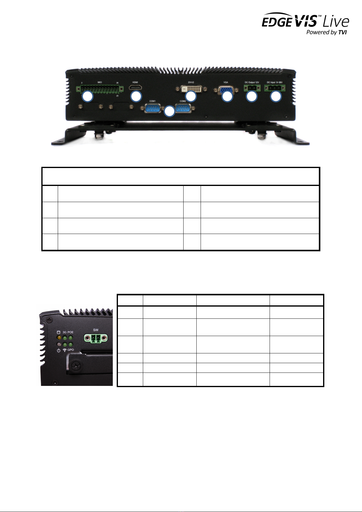
Rear Panel Layout
1
MIO (multi I/O) connector (for contact alarms)
5
12V power input connector
2
HDMI video connector
6
9-36V DV input
3
DVI-D video connector
7
2 x RS232 port
4
VGA video connector
Status indicators
The status LEDs on the top left of the front panel provides visual feedback on device status.
LED
Off
Flashing
On
Storage
HDD/SDD inactive
HDD/SDD reading or writing
N/A
3G
Modem not
powered
Modem powered, connected
and transferring data
Modem powered but
not transferring data
PoE
PoE not powered
N/A
PoE power
board active
GPO
Vehicle ignition off
N/A
Vehicle ignition on
Wi-Fi
Wi-Fi not powered
N/A
Wi-Fi powered
Power
System off
N/A
System on
1
2
3
4
5
6
7
EDGEVIS HD-IP450 HARDWARE INSTALLATION GUIDE
ISSUED: 10 NOVEMBER 2020 PAGE 6
Powering the device and switching it on/off
The HD-IP450 can be powered using an AC/DC power convertor (supplied) or direct from a vehicle battery. When
powering the device from the mains power supply, always use the AC/DC convertor supplied with the unit and
NEVER connect directly to mains voltage. Doing so will invalidate the warranty of the device.
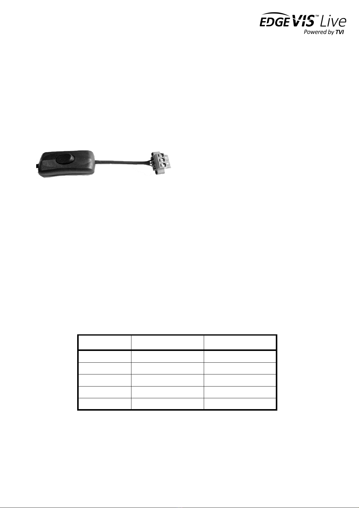
The AC/DC power convertor (PSU) that is supplied with the
HD-IP450 can be used to power the unit from the mains.
An in-line switch on this power supply emulates
connection/disconnection of a vehicle ignition connection
(see left). This switches +12V to the ignition input of the
HD-IP450 device.
The HD-IP450 is specifically designed for use in vehicle-
based applications. As such, it incorporates ignition based power switching. When the ignition is switched completely
off, the HD-IP450 will be powered down. To maintain power to the HD-IP450 while the vehicle is not running (engine is
off) the ignition key should be turned to the accessory (e.g. radio) position to maintain the +12V supply to the unit.
The ignition key should not be turned to the off position otherwise the HD-IP450 will begin powering down. For further
details on vehicle-based power connections, refer to Appendix B.
Connecting antennas for cellular and GPS connections
The front of the unit also includes antenna fixings for the internal modem (two antennas for 3G/4G cellular networks),
internal Wi-Fi module and GPS. Use antennas with screw fixings that are an appropriate form factor for the
deployment conditions. Antennas for each of these are supplied with the HD-IP450.
Default LAN port IP Addresses
For ease of deployment each LAN port on the HD-IP450 device is pre-configured with a static IP address:
!
!
LAN Port
Default IP Address
Subnet mask
USB to Ethernet
192.168.10.1
255.255.255.0
LAN1
192.168.11.1
255.255.255.0
LAN2
192.168.12.1
255.255.255.0
LAN3
192.168.13.1
255.255.255.0
LAN4
192.168.14.1
255.255.255.0

EDGEVIS HD-IP450 HARDWARE INSTALLATION GUIDE
ISSUED: 10 NOVEMBER 2020 PAGE 7
Connecting IP cameras
The HD-IP450 allows for connection of eight IP cameras via either of the LAN PoE ports located on the front of the
unit. Each camera should be connected to the device using standard Ethernet cable and will be powered by the HD-
IP450 if they are PoE compatible. Using more than four cameras will require the use of an external router (which can
also provide PoE power), and cameras that are not powered using PoE require an independent power supply.
Two ports are provided to allow separate connections between the HD-IP450 and the IP Cameras and internet
connection (e.g. an ADSL or SatCom router).
Refer to Section 1 of the IP Series, HD-Q800, 4K-R800 - Setup Guide for details on configuring the Ethernet ports and
IP cameras to work together. The list of specific cameras supported on the IP Series of products can be found on the
Support site: http://tvi-support.digitalbarriers.com
Connecting contact alarms
The device supports up to four simple contact alarms that can be connected to third-party devices. Once activated,
alarms are passed to EdgeVis Server and alerts viewed in EdgeVis Client. There are no other configuration steps
required. The Knowledge Base Article HD-IP450 - Using the contact alarms provides additional information on the
different ways to wire contact alarms, including those with and without external power supplies.
The HD-IP450 has a 26-pin MIO (multiple input/output) and a terminal block is supplied with the unit.
Pin
Signal
Specification
7
Ground
11
Input Alarm 0
Low = <0.8V
High = ~12V
Maximum current 100ma
13
Input Alarm 1
15
Input Alarm 2
17
Input Alarm 3
Connecting a PC/laptop to access the setup interface
When preparing the device using the IP Series Setup interface, the unit must be connected via Ethernet to a laptop
with a web. Since all four LAN ports on the HD-IP450 are intended for IP cameras connections and are configured with
static IP addresses as the default, a USB-to-Ethernet adapter is included for the purpose of device setup. Refer to
Section 1 of the IP Series, HD-Q800, 4K-R800 - Setup Guide for further details on laptop/PC connection.

EDGEVIS HD-IP450 HARDWARE INSTALLATION GUIDE
ISSUED: 10 NOVEMBER 2020 PAGE 8
Storage medium
The HD-IP450 incorporates a removable storage bay for a solid-state disk (SSD) or hard disk drive (HDD). An SSD drive
is recommended for greater reliability, particularly if using the HD-IP450 for vehicle-based applications. The disk can
be removed when the unit is powered off. When powered on, the disk can be ejected using the IP Series local web
interface. From within this interface, click on Storage option, select the desired disk, and then use the Eject device
menu option.
Additionally, it is possible to use external USB disks to store recordings. For further details, refer to Section 2 of the IP
Series, HD-Q800, 4K-R800 - Setup Guide.
Updating the software on the unit
Once notified of a new software release by Digital Barriers, updates are available for download from the EdgeVis
support site (see below for link) for installation onto the device.
There are three ways to update the firmware:
• To update remotely, upload the new firmware to the Firmware tab within the EdgeVis Server web interface
and then, from the Encoder tab, select Upgrade Firmware from the Select Action menu on the desired
encoder.
• Using the Upgrade Firmware option when logged into the encoder’s local web interface.
• Copy the firmware onto a USB flash drive and insert into a USB port on the front of the unit. The flash drive
can be inserted into a running unit or before the unit is powered up. The update procedure will take
approximately ten seconds, and then the encoder will beep four times. At this point it is safe to remove the
pen and the unit will automatically reboot. If the update fails the encoder will beep continually.
To access or register for the Digital Barriers Support Site, visit tvi-support.digitalbarriers.com

EDGEVIS HD-IP450 HARDWARE INSTALLATION GUIDE
ISSUED: 10 NOVEMBER 2020 PAGE 9
Section 2 - Configuring communications on the HD-IP450
The HD-IP450 supports communications over 3G/4G cellular, Wi-Fi and
wired LAN connections. A cellular connection requires the insertion of a
valid SIM card. Each of the communication methods are set up using the
HD-IP450 web-interface Comms Settings page. More detailed
information on HD-IP450 set up can be found in the IP Series Setup Guide.
Connecting over a 3G/4G cellular network
A valid mobile SIM card is required in order to connect the HD-IP450 over a cellular communications bearer. The unit
has an inbuilt modem for 3G/4G connection with two 3G/4G antenna connectors on the front of the device. Note:
despite the ultra-efficient bandwidth usage achieved by TVI, the HD-IP450 is considered a heavy data use product on
cellular networks. It is recommended that an unlimited data plan (or if unavailable, a heavy consumption data plan) is
setup with your Mobile Network Service Provider for use with the HD-IP450.
To insert a SIM card, locate the SIM card slot on the front of the HD-IP450 unit and insert a standard SIM card into the
slot with the metal contacts facing upwards. To eject a SIM card, push the eject tab that is located to the left of the
SIM slot and slide out the SIM card. The network settings (for your Mobile Network Service Provider) are entered
during device setup – details of which are covered in Section 2 of the IP Series, HD-Q800, 4K-R800 - Setup Guide.
NOTE: Both the 3G/4G and MIMO antennas should be connected to obtain the best cellular signal and throughput.
Connecting over a Wi-Fi network
When using Wi-Fi as the communications bearer, ensure that a suitable Wi-Fi antenna is connected to the antenna
connector on the front plate. Details for the Wi-Fi connection must be entered during the device setup – details of
which are covered in Section 2 of the IP Series, HD-Q800, 4K-R800 - Setup Guide.
Connecting over a wired LAN connection
When using a wired LAN connection as the communications bearer, connect an Ethernet cable into one of the LAN
connector on the front of the HD-IP450. If all four LAN sockets are being used for IP cameras, then the supplied USB to
Ethernet adapter can be used as a communications bearer.
Details for the LAN connection must be entered during the device setup – details of which are covered in Section 2 of
the IP Series, HD-Q800, 4K-R800 - Setup Guide.

EDGEVIS HD-IP450 HARDWARE INSTALLATION GUIDE
ISSUED: 10 NOVEMBER 2020 PAGE 10
Section 3 – Next Steps…
After unpacking the encoder, inserting a SIM card, and wiring up your
encoder the next step is to perform the initial setup, where comms
settings, server details and IP Cameras are configured.
Setting up the encoder
With the encoder unpacked and all of the physical setup complete it is time to set up the encoder so that it is available
on the EdgeVis Server for viewing. Refer to the IP Series, HD-Q800, 4K-R800 - Setup Guide for further details.

EDGEVIS HD-IP450 HARDWARE INSTALLATION GUIDE
ISSUED: 10 NOVEMBER 2020 PAGE 11
Appendix A - Troubleshooting and frequently asked
questions
How many channels does the HD-IP450 support?
The HD-IP450 can record up to eight cameras, and transmit one of those cameras. It is possible to create multiple
quad-views allowing four cameras to be transmitted simultaneously.
What level of recording and streaming performance is achievable?
Based on the processing power of the HD-IP450, the unit can typically achieve 25/30 fps of 1080p quality recording
whilst simultaneously streaming one 1080p quality video at 10 fps.
What recording functions does the HD-IP450 support?
The HD-IP450 can be set up to record continuously, or to record on an alarm trigger. Recordings can be set to
overwrite old recordings automatically, or to stop on full.
What indicative recording times and streaming rates are achievable?
The HD-IP450 records the incoming video stream from each IP camera without modification. The options set (e.g.
frame-rate, bandwidth) when configuring the IP camera will directly affect the recording time. Below are the
approximate recording times for four cameras and various storage options when the IP cameras are set to typical
settings:
Frame rate
IP Camera b/w
480GB SSD
960Gb SDD
1 fps
1.4 Mbps
8 days
16 days
6.25 fps
3 Mbps
4 days
8 days
12.5 fps
5 Mbps
2 days
4 days
25 fps
7 Mbps
1.5 days
3 days
Below are the approximate recording times for four SD cameras:
Frame rate
IP Camera b/w
480GB SSD
960Gb SDD
1 fps
100Kbps
100 days
200 days
6.25 fps
250 Kbps
40 days
80 days
12.5 fps
500 Kbps
20 days
40 days
25 fps
1 Mbps
10 days
20 days

EDGEVIS HD-IP450 HARDWARE INSTALLATION GUIDE
ISSUED: 10 NOVEMBER 2020 PAGE 12
What bearers can the HD-IP450 use to transmit video to EdgeVis Server?
The HD-IP450 includes an inbuilt 4G/LTE cellular modem for efficient streaming over commercially available cellular
networks. It can also transmit using its inbuilt LAN port or Wi-Fi module. EdgeVis optimises its transmission to the
characteristics of the bearer that it is being used to maximise performance.
What camera power requirements can the HD-IP450 support?
The HD-IP450 features Power-over-Ethernet (PoE) Class 0 ports and is therefore capable of supporting IP cameras
with up to approximately 15W power consumption per camera. Non-PoE cameras require a separate power supply.
Note: The HD-IP450 ships with a 75W power supply, which may not be powerful enough to supply PoE to all four
cameras (if each is using close to the maximum 15W supported). Digital Barriers can supply a higher wattage power
supply for those customers who require more power than the 75W can supply – contact your supplier for further
details.
How does EdgeVis Server licensing work in relation to the HD-IP450?
The EdgeVis Server licensing model is based on the number of cameras connected to the encoder. An HD-IP450 unit
therefore requires up to eight encoder licences for licensing purposes (if all eight cameras are being utilised). These
licences must either be of type EdgeVis Lite, Enhanced or Enterprise, depending on the feature set desired.
What storage options are supported on the HD-IP450?
To sustain extended usage, it is recommended that a robust enterprise-class 2.5” hard disk drive (HDD) or solid-state
drive (SSD) be used. The latter is particularly recommended for vehicle-based deployments with constant vibration. It
should be noted that the maximum height of an HDD device is limited to 9.5mm.
Which IP cameras are supported by the HD-IP450?
The list of specific cameras supported on the IP Series of products can be found on the Support site:
http://tvi-support.digitalbarriers.com.

EDGEVIS HD-IP450 HARDWARE INSTALLATION GUIDE
ISSUED: 10 NOVEMBER 2020 PAGE 13
Appendix B – Vehicle Installation
The HD-IP450 unit is specifically designed for in-vehicle deployment. It
features a vibration-resistant mounting plate, battery power inputs
vibration-resistant storage caddy. A solid-state disk should be used for in-
vehicle applications.
Dimensions and fixings for in-vehicle installation
Ensure that you have adequate space to install the HD-IP450 mounting plate and unit with access to the camera
inputs, antenna connections and removable storage device on the front plate. The 9~36V battery input power
terminals are located on the rear plate of the unit and should be factored in when siting the unit in a vehicle.
Appendix C provides diagrams that outline all encoder dimensions and positioning of mounting holes.
Connecting the HD-IP450 to a vehicle battery
The HD-IP450 can be powered directly from a vehicle battery – either a 12V or 24V power source. When the ignition is
turned off the device will power down after a defined set time. To use the device while parked, apply power by turning
the key to accessory mode.
When installing in a vehicle, the following connections must be made to the power input connectors on the rear of the
unit:
• Connect negative battery wire to the contact marked ‘-‘ on
the DC input connector
• Connect positive battery wire to the contact marked ‘+’ on
the DC Input connector
• Connect ignition wire to the contact
marked ‘IG’ on the DC Input connector
DC Input 9~36V
IG+ _
_
+

EDGEVIS HD-IP450 HARDWARE INSTALLATION GUIDE
ISSUED: 10 NOVEMBER 2020 PAGE 14
Appendix C - External Device Dimensions

EDGEVIS HD-IP450 HARDWARE INSTALLATION GUIDE
ISSUED: 10 NOVEMBER 2020 PAGE 15
FCC COMPLIANCE
This equipment has been tested and found to comply with the limits of a Class B digital device, pursuant to Part 15 of the FCC Rules. These limits are designed
to provide reasonable protection against harmful interference in a residential installation. This equipment generates, uses and can radiate radio frequency
energy and, if not installed and used in accordance with instructions, may cause harmful interference to radio communications. If this equipment does cause
harmful interference to radio or television reception, which can be determined by turning the equipment off and on, the user is encouraged to try to correct
the interference by one or more of the following:
• Reorient or relocate the receiving antenna
• Increase the separation between the equipment and receiver
• Connect the equipment to an outlet on a circuit different from that to which the receiver is connected
The EdgeVis HD-IP450 unit contains a radio module that has been FCC Approved for fixed and mobile applications (FCC ID: RI7UC864G).
The radio module conforms to the following US Directives;
• Use of RF Spectrum. Standards: FCC 47 Part 22
• Use of RF Spectrum. Standards: FCC 47 Part 24
• EMC (Electromagnetic Compatibility). Standards: FCC47 Part 15
The EdgeVis HD-IP450 Encoder contains a radio module that has been FCC Approved for fixed and mobile applications (FCC ID: ZCN722MV1).
The radio module conforms to the following US Directive;
• Use of RF Spectrum. Standards: FCC 15 Part C.
FCC Warning: changes or modifications not expressly approved by the party responsible for compliance could void the user's authority to operate the
equipment.
To meet the FCC’s RF exposure rules and regulations:
• The use of a non-shielded interface cable with the EdgeVis HD-IP450 Encoder device is prohibited
• The power cord must be 3m (10 feet) or less in length and a ferrite should be fitted within 5cm (2 inches) of the equipment
• The antenna(s) used with the EdgeVis HD-IP450 unit must be installed to provide a separation distance of at least 20cm (8 inches) from all persons
and must not be co-located or operating in conjunction with any other antenna or transmitter
• The antenna(s) used with the EdgeVis HD-IP450 unit must not exceed 3dBi
The EdgeVis HD-IP450 unit shall only be used for fixed and mobile applications.
CE COMPLIANCE STATEMENT
The EdgeVis HD-IP450 Encoder complies with the following European Union Directives:
• Low Voltage Directive 2006/95/EEC for product safety
• Directive 89/336/EEC for EMC conformity
The EdgeVis HD-IP450 Encoder contains a radio module that has been approved for integration into fixed and mobile applications. The radio&module
conforms to the following European Union Directives:
• R&TTE Directive 99/05/EC (Radio Equipment & Telecommunications Terminal Equipment)
• Low Voltage Directive 73/23/EEC for product safety
• Directive 89/336/EEC for EMC conformity
In order to satisfy the essential requisite of the R&TTE 99/05/EC directive, the radio module is compliant with the following standards:
• Radio Spectrum, Standard: EN 301 511, EN 301 908-1 and EN 301 908-2
• EMC (Electromagnetic Compatibility). Standards: EN 301 489-1, EN 301 489-7 and EN 301 489-24
• LVD (Low Voltage Directive) Standards: EN 60950-1:2001+A11:2004
The use of this product may be dangerous and has to be avoided in the following areas:
• Where it can interfere with other electronic devices in environments such as hospitals, airports, aircraft, etc.
• Where there is risk of explosion such as gasoline stations, oil refineries, etc.
The user must ensure that:
• The antenna(s) used with the EdgeVis HD-IP450 unit must be installed to provide a separation distance of at least 20cm from all persons and must
not be co-located or operating in conjunction with any other antenna or transmitter
• The antenna(s) used with the EdgeVis HD-IP450 unit must conform to the requirements stated in the installation guide
• The EdgeVis HD-IP450 unit shall only be used for fixed and mobile applications
It is responsibility of the user to enforce the country regulations and specific environment regulations.
Table of contents
Popular Automobile Accessories manuals by other brands


ULTIMATE SPEED
ULTIMATE SPEED 279746 Assembly and Safety Advice

SSV Works
SSV Works DF-F65 manual

ULTIMATE SPEED
ULTIMATE SPEED CARBON Assembly and Safety Advice

Witter
Witter F174 Fitting instructions

WeatherTech
WeatherTech No-Drill installation instructions

TAUBENREUTHER
TAUBENREUTHER 1-336050 Installation instruction