DIGITAL DELAY Crossover Plus with 4-Stage Timer User manual

1
2036 Fillmore Street
Davenport, Ia. 52804
563-324-1046
www.racedigitaldelay.com
1014-SCR
WARRANTY AND DISCLAIMER
DIGITAL DELAY INC. WARRANTS THE PRODUCTS IT
MANUFACTURES AGAINST DEFECTS IN MATERIALS AND WORKMANSHIP
FOR A PERIOD LIMITED TO 1 YEAR FROM THE DATE OF SHIPMENT,
PROVIDED THE PRODUCTS HAVE BEEN STORED, HANDLED, INSTALLED,
AND USED UNDER PROPER CONDITIONS.
The company’s liability under this limited warranty shall extend only to the
repair or replacement of a defective product, at the company’s option. DIGITAL DELAY
INC. disclaims all liability for any affirmation, promise, or representation with respect to
the products.
The customer agrees to hold DIGITAL DELAY INCORPORATED harmless
from, defend, and indemnify DIGITAL DELAY INC. against damages, claims, and
expenses arising out of subsequent sales of or use of DIGITAL DELAY INC. products, or
products containing components manufactured by DIGITAL DELAY INC. and based
upon personal injuries, deaths, property damage, lost profits, and other matters which
BUYER, its employees, or sub-contractors are or may be to any extent liable, including
without limitation, penalties imposed by the Consumer Product Safety Act (P.L. 92-573)
and liability imposed upon any person pursuant to the Magnuson-Moss Warranty Act (P.L.
93-637), as now in effect or as amended hereafter.
No warranties expressed or implied, are created with respect to the company’s
products except those expressly contained herein. The customer acknowledges the
disclaimers and limitations contained and relies on no other warranties or affirmations.

2
2036 Fillmore Street
Davenport, Ia. 52804
563-324-1046
www.racedigitaldelay.com
Crossover Plus
with
4-Stage Timer
Instructions
The Crossover Plus with 4-Stage Timer is the latest in a full line of electronic racing products
from Digital Delay, Inc.. Designed to be more reliable and user friendly than any other multi-function
delay box on the market. The Crossover Plus with 4-Stage Timer has a 16 digit keypad for fast and
precise entry of information into the unit while two illuminated multi-segment liquid crystal displays are
used to display all relative information.
Contents:
Warranty and Disclaimer................................................................... Page 1
Features, Applications, and Specifications............................……… Page 3
Quick Reference Diagram.................................................................. Page 4
The Terminal Strip............................................................................. Page 5
The Displays....................................................................................... Page 6
The Keypad......................................................................................... Page 7
Setting Dial-Ins, Delay, and Stage Times................................……… Page 8
Setting Throttle Mode......................................................................... Page 8
Setting Push Button Mode and Interrupt Time.......................………. Page 9
Setting and Displaying the Bump Push Button.......................……… Page 9
How Late............................................................................................ Page 9
Wiring and Testing the Unit............................................................. Page 10
Explanation of the 4-Stage Timer...............................................……Page 11

3
Specifications
Features:
• Discrete solid state I/O (input - output) construction
• Microprocessor controlled timing with accuracy to 0.0001 of a second
• Retains all numbers even with power disconnected from unit
• Large displays for easy reading of times
• Low voltage warning and full status indication
• Illuminated liquid crystal displays for both day and night use
• Dust & splash proof display lenses & key pad with detent ( positive feel)
• 1 or 2 pushbutton, bump up or down, by-pass, over ride features
• Easy and fast selection or entry of all information even with gloves
• Self test mode on all displays functions
• Both Transbrake and Throttle control outputs
• Very high current output (20 Amps)
• Instant timing cycle reset
••••••••••••••••••••••••••••••••••••••••••••••••••••••••••
Applications:
• Controls Transbrake Solenoids
• Controls Starting Line Throttle Stops
• Controls Throttle Stops
• Controls Nitrous Solenoids
• Controls 2-Steps
••••••••••••••••••••••••••••••••••••••••••••••••••••••••••
Specifications:
•Input Voltage Range: 10 to 16 volts DC
•Dial-In Time Range: 00.00 to 99.99 seconds in .01 increments
•Delay Time Range: 0.000 to 9.999 seconds in .001 increments
•Stage 1 and 2 Time Range: 0.000 to 9.999 seconds in .001 increments
•Stage 3 and 4 Time Range: 00.00 to 99.99 seconds in .01 increments
•Transbrake Output Current: 20 Amps.
•Throttle Output Current: 20 Amps.
•Operating Temperature Range: 0 to 150 degrees F.

4

5
The Terminal Strip
+12VDC Terminal: Connect the +12VDC terminal to a switched +12
volt source with enough amperage capable of driving both the
transbrake and the throttle stop at the same time.
Transbrake Terminal: Connect the Transbrake terminal to the
Transbrake solenoid. Connect the low side of the 2-Step here if
used.
Throttle Stop Terminal: Connect the Throttle Stop terminal to any
device that you want controlled by the stage times.
Ground Terminal: Connect the Ground terminal to the Neg. terminal
on the battery or to a good steel ground, not aluminum.
Bypass Terminal: Connect the Bypass terminal to an optional push
button. This allows you to activate any device that is connected to
the Transbrake terminal without running a timing cycle. An example
of this would be vehicles that require the transbrake solenoid to be
engaged when backing up the vehicle. The bypass terminal can also
be used as an override if you flinch in single Push Button Mode at the
starting line. Simply press and hold the bypass push button and go
off your bottom bulb, avoiding the red light due to flinching.
Button-1 Terminal: In single Push Button Mode the push button
connected to Button-1 terminal is used to control the primary
delay and the secondary delay in sequence. In dual Push Button Mode
the push button connected to Button-1 terminal is used to control
the primary delay only.
Button-2 Terminal: In single Push Button Mode this terminal is
disabled and has no affect on the operation of the unit. In dual Push
Button Mode the push button connected to Button-2 terminal is used
to control the secondary delay only.
Bump Terminal: Connect to the Bump terminal an optional push
button. This allows you to subtract or add a programmable amount
of time from the first delay time started every time the Bump Push
Button is depressed. One second after the transbrake releases, the
Bump Push Button will override the throttle control if pressed.

6
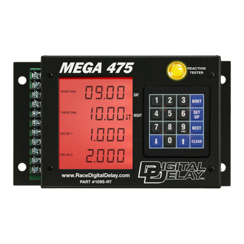
The Displays
There are two displays, A and B, that are used to show all relative information about the
Crossover Plus with 4-Stage Timer. Each display can display up to six different times or mode settings.
Display A: The six shown on Display A are Your Time, Delay 1 Time,
Number of Bumps, P.B. mode, Stage 1 Time, and Stage 3 Time.
Display B: The six shown on Display B are Their Time, Delay 2 Time,
How Late Time, Throttle Mode, Stage 2 Time, and Stage 4 Time.
There are six red L.E.D.s to the right of the key pad. The information being displayed
corresponds to the text that is to the right of the lit L.E.D.. For example if the L.E.D. next to the text
“Dial-Ins” was lit, Display A would be showing Your Time and Display B would be showing Their Time.
Other special functions of the displays are:
Low voltage indication: The numbers on both displays will flash
indicating the voltage to the unit is below the recommended 11.5
Volts.
Transbrake-Colons: When the transbrake is engaged both colons will
turn on and when the delay timer starts counting down both colons
will flash.
Stage Time-Arrows: When stages 1 and 2 are being displayed both
arrows will turn on. When stages 3 and 4 are being displayed both
arrows will flash. If stage 1 or 2 is counting down, the arrow for
that stage will turn on. If stage 3 or 4 is counting down, the arrow
for that stage will flash.
Bump Arrow: When the Bump information is being displayed and
the arrow in Display A is on, the unit is set in bump up mode. If
there is no arrow the unit is in bump down mode.

7
The Keypad
The keypad is made up of numerical and function keys that are used to control the information
that is either entered or shown on the displays. The numerical keys 0-9 are used only to enter new times.
The function keys A-F are used to control different functions of the unit.
Function Keys A and B
The function keys A and B correspond to displays A and B respectively and are used with the
numerical keys when entering new times. For example to enter a new time into Display A, press the A
key on the key pad. Display A will blank out indicating it is ready to accept a new time. Next use the
numerical keys to enter the new time into the unit, leading zeros do not have to be entered. As the
numbers are entered they will appear on the display indicating that the number was accepted and stored
into memory.
If an error is made while entering, press the appropriate A or B key to erase the last digit. This
can be repeated as many times as necessary until the display is blank.
Function Keys C, D, and E
The function keys C, D, and E are used to select what information is shown on the displays. The
corresponding six red L.E.D.s, two for each key, indicate when lit, what information is being displayed.
For example, if the Dial-Ins are wanted and the First and Second Stage Times are being displayed, the C
key would be pressed to display the Dial-Ins. If the C key was then pressed again the Delay-1 time and
Delay-2 time would replace the Dial-Ins.
Function Key F
The function key F controls three separate functions.
1) If pressed during a timing cycle, the timing cycle will be cancelled
and the unit will be reset. This constitutes a master reset for the
timing cycle.
2) If pressed when the unit is not running a timing cycle, the Dial-Ins
will be displayed and set to all zeros, making it ready for new
Dial-Ins before next run.
3) If the F key is held down while the power is being turned on, the unit
will go into a special test mode. This is described in Testing of the
Unit.

8
Setting Dial-In Times
To set a new Dial-In time into either Your Time or Their Time press the C key until the Dial-In
times are being displayed. To enter a new number press the corresponding letter key (A or B) to the
display containing the Dial-In time to be changed. The selected display will go blank indicating the unit
is ready to accept the new Dial-In time. Enter the new Dial-In time using the numerical keys, leading
zeros do not have to be entered. For example if 9.90 for a Dial-In time is desired 990 would be entered on
the key pad. As the numbers are entered they are shown on the display, indicating the numbers are
accepted and entered into memory. If a mistake is made while entering the number, depressing the
corresponding letter key (A or B) for the display again will erase the last digit entered. This can be
repeated as many times as necessary until the display is blank.
Setting Delay Times
To set a new delay time into either Delay 1 or 2 press the C key until the delay times are
displayed. Then follow the same procedure for entering a new number as instructed in setting new Dial-
In times.
Setting Stage Times
To set a new stage time into any of the stages press the E key until the stage time to be changed is
displayed. Then follow the same procedure for entering a new number as instructed in setting new Dial-
In times.
Setting Throttle Mode
To set the Throttle Mode press the D key until the Throttle Mode is shown on Display B. Display
B will show a “0101” or “ 1010”, to switch to the opposite setting press the B key once. A “0” means
zero Volts out and a “1” means 12 Volts out. In racing terms this is also referred to as “0” normally open,
“1” normally closed. (“0101” means off/on/off/on)

9
Setting Push Button Mode
and the
Push Button Interrupt Time
To set the Push Button Mode press the D key until the Push Button Mode is shown on Display A.
The left most digit shows “1” or “ 2” to indicate which Push Button Mode the unit is in, when in 1 Push
Button Mode, the First P.B. starts both the primary and secondary delays. When in 2 Push Button Mode,
one or both push buttons can be used in any sequence, the First P.B. starts the primary and Second P.B.
starts the secondary delay. The two right digits show the programmable amount of time (00 to 99
seconds) that after the transbrake releases, Button 1 and Button 2 push button inputs are disabled. To
change either the Button Mode or the Interrupt Time first press the A key, then enter a “1” or “2” for the
Push Button Mode followed by a two digit number representing the Push Button Interrupt Time. For
example “1 10” would indicate single Button Mode with a 10 second Interrupt Time. If no Push Button
Interrupt Time is wanted enter “00” after pressing a “1” or “2” for the Push Button Mode.
Setting and Displaying the
Bump Information
To display the Bump information press the D key until the Bump information is shown on
Display A. The left most digit shows the programmable time (1 to 9 hundredths of a second) to be added
to or subtracted from the delay time every time the Bump push button is pressed. To change the number,
press the A key and enter the new number (1-9). To switch between the bump up modes press the A key
followed by the B key, then the number desired (Arrow on means bump up, no arrow means bump down).
The two right digits show the number of times the Bump push button was pressed. The Bump time will
only affect the first delay time started.
How Late
To display the How Late information press the D key until the How Late information is shown on
Display B. If the transbrake is released on Delay-2 (4-Digit) the left most digit will display an “8”, if not,
it will be blank. The remaining digits display the How Late time. For example if the number displayed is
“8.012” and your reaction time was .510 on the time slip, add the How Late time to the .510 for a total
reaction time of .522 on the crossover delay.
NOTE: Both How Late and Bump information is stored in memory
until a new How Late or the Bump number replaces it.

10
Wiring and Testing the Unit
To test the four push button inputs and the four yellow L.E.D.s, disconnect all wires going to the
four push button inputs. Next take a piece of wire, connect one end to ground, then touch the other end
to each of the four push button inputs. As the inputs are touched by the wire the corresponding yellow
L.E.D. should light.
The Crossover Plus with 4-Stage Timer has a built-in test mode for the displays and the red
L.E.D.s. The function key F is held down while the power is being turned on, the unit will go into a test
mode and stay in the test mode until the F key is released.
While in test mode:
1) The displays will start at “0000” and count up, adding “1111” to the
number shown on both displays every half second.
2) While the numbers are counting up, the decimal points will switch
back and forth between “00.00” and “0.000” while both the arrows
and colons will flash.
3) The six red L.E.D.s will flash back and forth every half second.
4) Both the transbrake and throttle outputs will be off during the test.

11
Explanation of the 4-Stage Timer
This is to help the racer understand the 4-Stage Timer when controlling a throttle stop. The 4-
Stage Timer can also be used to control other timed devices, nitrous, or timing retarders.
Stage 1 represents when the throttle stop turns on. Stage 2 represents the amount of time
(duration) the throttle stop will stay on. Stage 3 represents when the throttle stop will turn on the second
time during the run. Stage 4 represents the amount of time (or duration) the throttle stays on the second
time. Both Stage 1 and Stage 3 start counting from the release of the transbrake. Stage 2 starts counting
after the amount of time set in Stage 1 is completed. Stage 4 starts counting after the amount of time set in
Stage 3 is completed.
Possible 8.90 S/C pass
Timer 1= 1.000
Timer 2= 2.000
Timer 3= 08.00
Timer 4= 00.50
This manual suits for next models
1
Table of contents
Other DIGITAL DELAY Automobile Accessories manuals
Popular Automobile Accessories manuals by other brands
Global Target Enterprise
Global Target Enterprise CK802D quick guide

Brodit
Brodit ProClip 804729 installation instructions

Classic Accessories
Classic Accessories FAirway Golf Car Seat Cover instructions
DV8
DV8 SPJL-10 Product installation manual
UltraGauge
UltraGauge EM Installation & operation

Fishbone Offroad
Fishbone Offroad FB23083 installation instructions
