DIGITAL DELAY Mega 475 User manual

- 1 -
www.RaceDigitalDelay.com
Mega 475
Instruction
Manual

- 2 -
The
MEGA 475
From
DIGITAL DELAY
2036 Fillmore Street
Davenport Iowa 52804
563-324-1046 www.RaceDigitalDelay.com
Congratulations on your purchase of the Mega 475
the latest delay box from Digital Delay. The Mega 475 is the
first Delay box from Digital Delay to control a digital Dial
Display board. The Mega 475 can control any Digital Delay
version 2 Dial Display boards, including multiple display
boards and our Dual View display boards.
To design the Mega 475 we started with the Mega
450 added the new ability to control a Dial Display board.
Then we further improved the design by adding some new
features and upgrading others, while retaining everything
that made the original Mega 450 the bestselling Delay Box.
The Mega 475 may seem overwhelming at first. But
even if you have never owned a Mega or Elite series Delay
Box, the layout of the screens, and the commonality of how
data is entered and viewed on the screens, eases the learning
process of the Mega 475.
Digital Delay also offers a wiring kit for the Mega
475 to help with the installation. Please call or check our
website for more information.

- 3 -
Upgrading from a
Mega 350,450, or Elite 500
If you are upgrading from a Mega 350, 450 or an
Elite 500 you will find the Mega 475 is similarly laid out.
The Keypad is the same and the screens are laid out in the
same four-line fashion. For the most part, the six blue
function keys; BRKT, Setup, Next, Clear, Up Arrow and
Down Arrow, work the same. Switching between Bracket
and Pro is also done in the same fashion as the earlier units.
Pressing the Setup key followed by the number 9 key sets the
unit in Pro Mode. Pressing the Bracket key (BRKT) sets the
unit in Bracket Mode.
While there are new features in the Mega 475, the
biggest change is the ability to directly control our full line
of V2 Dial Display boards. Just enter a new value for Your
Dial and the number is automatically displayed on the Dial
Display Board.
The Mega 475 also has the Set and Go Push-button
Mode. This Push-button Mode uses the press of one button
to apply the Transbrake solenoid. Then on the press of a
second button the timing starts counting down.
Even if you feel very comfortable with how the
earlier boxes work, it is recommended you review the
following upgrades to these features.
S.L.E. Starting Line Mode Page 34
Pro Shift Control Page 22
Replay Tach Page 47
Push-button Mode 5 Page 29
Dial Board Control Page 43
Wiring Dial Board Page 65

- 4 -
MEGA 475
Table of Contents
Upgrading from a 350, 450 or 500……..……….......Page 3
Basic Overview of the Mega 475…..……….……....Page 9
Getting Started (Basics for Keypad and Screen)……Page 10
Initial Setup of the Mega 475...….…....…...………..Page 11
Setting Bracket and Pro Mode Screens……………..Page 11
Bracket Mode Screens
Dial-in and Delay……………………..…….Page 12
Special Functions Screen 1………………… Page 13
Special Functions Screen 2…….…………... Page 14
Timers 1 and 2……...……………………… Page 15
Shift Control……………..……………….... Page 16
Dial Board Intensity Control….…………….Page 17
Driver’s Reaction Tester…............................Page 18
Replay Tach…….....……………..……….... Page 19
Pro Mode Screens
Pro Screen………………………..……….... Page 20
Timers 1 and 2……….…………..……….... Page 21
Shift Control……………..……………….... Page 22
Driver’s Reaction Tester……........................Page 23
Replay Tach…….....……………..……….... Page 24
Understanding
Dial-in and Delays...……..……………….... Page 25
Special Functions Screen 1..……..……….... Page 27
Special Functions Screen 2…….…………... Page 33
Timers……………………………………… Page 36
Throttle Mode..…………..……………….... Page 38
Canceling a Timing Cycle with Clear Key… Page 38

- 5 -
Shift Control……....……………..……….... Page 39
Dial Board Control…….……........................Page 43
Driver’s Reaction Tester……........................ Page 45
Replay Tach…….....……………..……….... Page 47
Push-button Inputs….…..………..……….... Page 49
Button 1…………………….……….Page 49
Button 2…………………….……….Page 52
Tap Button……...………….….…… Page 53
Line Lock Button…….………….…. Page 54
Additional Button Functions Chart....Page 55
WiringThe Terminal Strip………………………….Page 56
Additional Wiring Help………...........…….. Page 61
Three Wire Push-button….…..….….Page 61
High Current Relay………..…….…. Page 61
Grounding Relay………….…….…. Page 61
Back-Up Feature ………….…….…. Page 62
Bypass Button……………..…….…. Page 62
Recommended Wire Gauge……….....…….. Page 63
Wiring Diagram…………...…............…….. Page 64
Checking the Screen Before Mounting……..Page 64
Wiring the Dial Display Board…………….. Page 65
Warranty
Warranty and Disclaimer…………………... Page 66
Categorized Contents
Bracket
The Push-button Features
Setting P.B. Mode and Interrupt Time.......…Page 13
Push-button Mode………………..…....…....Page 29
Push-button Interrupt Time……...…….…....Page 31
Understanding The Push-button Inputs…..... Page 49

- 6 -
Back-up Feature……………………………. Page 62
Bypass Button…………………………….... Page 62
Additional Button Functions Chart……........Page 55
Bracket Tap Up/Down
Setting Tap Up/Down……....……………… Page 13
Understanding Tap Features……………….. Page 27
Additional Button Functions Chart……........Page 55
Bracket Timers
Setting Timers 1 and 2…...………………… Page 15
Setting Throttle Mode …………...………....Page 15
Setting Timer Range………………..…….... Page 14
Setting P.T.S.O. ………...………………..... Page 14
Understanding The P.T.S.O….…..……….... Page 35
Understanding The Timers..……..……….... Page 36
Understanding Throttle Mode..…..………....Page 38
Understanding Timer Range....…..……….... Page 35
Bracket S.L.E.
Setting S.F.O. Mode to 1 (S.L.E.)…………..Page 13
Setting S.L.E. ……........................................Page 14
Understanding the S.L.E................................Page 33
Understanding Tap Button.............................Page 53
Additional Button Functions Chart……........Page 55
Bracket Line Lock
Setting S.F.O. Mode to 3 (Line Lock)……... Page 13
Understanding S.F.O. Modes…...…..............Page 32
Understanding Line Lock Button……...……Page 54
Additional Button Functions Chart……........Page 55
Bracket Shifts
Setting Shift Control...………..…….............Page 16
Understanding Shift Control Screen.…….... Page 39

- 7 -
Understanding Tach and Peak RPM……...... Page 39
Understanding Shift Points………....…….... Page 39
Understanding Shift Number……....……..... Page 40
Understanding Shift Mode……….....……....Page 40
Understanding Shift by Time or RPM…....... Page 40
Changing the Shift Points………………….. Page 41
Testing the Shift features…….....…..…….... Page 42
The Reaction Tester Screen
Bracket…..…………………………………. Page 18
Understanding Reaction Tester Screen…......Page 45
Replay Tach Screen
Bracket…..…………………………………. Page 19
Understanding Replay Tach Screen….…......Page 47
Dial Display Control
Setting Dial Board Intensity..……………….Page 19
Understanding Dial Board Control…..…...... Page 43
Turning off the Dial Board Feature……...… Page 44
Wiring the Dial Display Board………..…… Page 65
Categorized Contents
Pro
Pro Timers
Pro Screen……………………….…………. Page 20
Setting Timers 1 and 2…...………………… Page 21
Setting Throttle Mode …………...……….... Page 21
Setting Timer Range………………..…….... Page 14
P.T.S.O. ………………………………….....Page 14
Understanding The P.T.S.O….…..……….... Page 35
Understanding The Timers..……..……….... Page 36
Understanding Throttle Mode..…..………....Page 38
Understanding Timer Range....…..……….... Page 35

- 8 -
Pro S.L.E.
Understanding the S.L.E................................Page 34
Understanding Tap Button ............................Page 53
Additional Button Functions Chart……...... Page 55
Pro Line Lock
Setting S.F.O. Mode to 3 (Line Lock)……... Page 13
Understanding Line Lock Mode..….............. Page 32
Understanding Line Lock Button……...……Page 54
Additional Button Functions Chart……........Page 55
Pro Shifts
Setting Shift 1 on Pro Screen………………. Page 20
Setting Shift Control...………..……............. Page 22
Understanding Shift Control Screen.…….... Page 39
Understanding Tach and Peak RPM……...... Page 39
Understanding Shift Points………....…….... Page 39
Understanding Shift Number……....……..... Page 40
Understanding Shift Mode……….....……....Page 40
Understanding Shift by Time or RPM…....... Page 40
Changing the Shift Points………………….. Page 41
Testing the Shift features…….....…..…….... Page 42
The Reaction Tester Screen
Pro…………...……………..………............. Page 23
Understanding Reaction Tester Screen…......Page 45
Replay Tach Screen
Pro…………...……………..………............. Page 24
Understanding Replay Tach Screen….…......Page 47

- 9 -
Basic Overview
The Mega 475 is our first Delay Boxes to control a
Dial Display board. When you enter a new time for Your
Dial it is automatically sent to the Dial Display board. No
extra control box needed. The Mega 475 is compatible with
all of our version 2 Dial Display boards including multiple
Dial Display boards and our Dual View Display boards. The
Mega 475 also has separate Day and Night intensity settings.
The Mega 475 is really two Delay Boxes in one, a
Bracket Delay Box and a Pro Delay Box each with their own
independent screens and settings. There are nine Bracket
Mode screens and seven Pro Mode screens.
The Mega 475 has the capability to run two 4-Stage
Timers at one time. The 4-Stage Timers are labeled Timer 1
and Timer 2. Each of the Timers has its own set of settings
for both Bracket and Pro Modes.
The Mega 475 can also shift the vehicle by time or
RPM, up to five shifts. Here again, the shifter has separate
shift points for both Bracket and Pro Mode.
The Tach and Replay Tach are accurate to 50 RPM
increments. The Tach also has a built-in peak RPM feature.
The Replay Tach can now store up to 9 passes for later
review on the screen of the Mega 475. The Replay Tach can
also store any shifts made by the Mega 475.
The Startling Line Enhancer (S.L.E.) can be set from
0.00 to 9.99 seconds in Bracket Mode. In Pro Mode the
S.L.E. now has a fixed Hold Time. This allows the
Transbrake solenoid to fully set before the engine goes to
full throttle. The all new S.L.E. Starting Line Mode allows
the driver to select if the Transbrake Button will set the
S.L.E. or not.
The Mega 475 is the first Mega series box that allows
ability to be able to Tap Up and Down in the same pass.
This can be done in any Push-button Mode except 2 and 5.

- 10 -
Getting Started
Before using the Mega 475, a basic understanding of
how the screens and keypad are structured, is needed.
Basics for the Screen and Keypad
There are two home screens, one for Bracket Mode
and one for Pro Mode. The Bracket Screen is the home
screen for Bracket Mode. The Bracket Screen has the Dial-
ins and Delays settings. The Bracket Screen can be returned
to at any time by pressing the Bracket key (BRKT) on the
keypad. This will also put the Mega 475 into Bracket Mode.
The Pro Screen is the home screen for Pro Mode. The Pro
Screen can be returned to at any time by pressing the Setup
key followed by the Number 9 key. This will also put the
Mega 475 into Pro Mode.
All of the screens have four lines of information. A
line displaying “ -- “ indicates that feature or time is turned
off. For most screens, the text is to the left of each line to
tell you what value or mode setting is being displayed for
that line. The exceptions are the Replay Tach and the
Driver’s Reaction Tester, which do not have the text.
On the far right side of the screen, Selection Arrows
are used to show which line is currently selected. The Next
key is used to move the Selection Arrows. When the Next
key is pressed the Selection Arrows will move to the next
available line on the screen. If the bottom line is selected
and the Next key is pressed, the Selection Arrows will move
to the top most available line.
If the selected line has a number value, pressing the
Clear key will clear the number allowing a new value to be
entered using the numerical keys. Also often when a line
with a number value is selected, pressing the Up Arrow or
Down Arrow key will cause the value to increase or
decrease by one each time the Arrow key is pressed.

- 11 -
If the selected line has a mode setting, use the Up
Arrow or Down Arrow key to change the mode settings. In
a few cases the Zero key is used to change mode settings.
Example, the Zero key changes Throttle mode for the
Timers.
The Setup key is used to view other screens, each
time the Setup key is pressed the next screen will be shown.
Note: The only way to get to the Bracket home screen is to
press the Bracket (BRKT) key.
Initial Setup of the Mega 475
When the Mega 475 arrives and you turn it on, you
will see the Bracket Mode Dial-In and Delay Screen. With
the initial factory settings, the Mega 475 will function as a
basic Crossover Delay Box, without any changes done to it.
To use the additional features of the Mega 475,
information needs to be entered. There are two sets of
screens, one set for Bracket Mode and one set for Pro Mode.
Some of the features can only be set while in Bracket Mode.
For example, the S.F.O. Mode is only accessible when in
Bracket Mode. For this reason it is recommended that you
setup the Bracket Mode screens first. Once the initial
settings have been entered, most will not need to be changed
unless the setup of the vehicle is changed.
Setting Bracket & Pro Mode Screens
The next section of the instructions will list what is
on each line of the 9 Bracket screens (pages 12-19) and the 6
Pro screens (pages 20- 24). Also listed, are which keypad
keys are used, to change the value or setting for each line.

- 12 -
The Dial-In and Delay Screen
Bracket Mode Screen 1
The Dial-in and Delay screen is the “home” Bracket
Mode screen. Press the BRKT key to return to this screen at
any time. This screen is where you enter your dial-in and
delay times.
The Selection Arrows on the right side of the screen
are used to show the line that is currently selected.
Use the NEXT key to change the selected line.
Your Dial
Use the CLEAR key, then use the NUMERICAL
keys to enter a time. Or use the or key to increase or
decrease the time by one. Dial Display explained page 43.
Their Dial
Use the CLEAR key, then use the NUMERICAL
keys to enter a time. Or use the or key to increase or
decrease the time by one.
Delay 1
Use the CLEAR key, then use the NUMERICAL
keys to enter a time. Or use the or key to increase or
decrease the time by one.
Delay 2 (used for second hit at the tree)
Use the CLEAR key, then use the NUMERICAL
keys to enter a time. Or use the or key to increase or
decrease the time by one.
The Delay 2 line is only used with Push-button
Modes 2, 3, or 4.
Press the SET UP key to go to the Special Functions
Screen 1.

- 13 -
Special Functions Screen 1
Bracket Mode Screen 2
The Tap features allow you to make adjustments to
the Delay time, as it is being counted down. The How Late
shows the amount of time that was remaining on the unused
Delay when taking two shots at the tree. The Push-button
Mode controls how the Mega 475 handles the push-buttons
to start a pass. The S.F.O. Mode controls what the S.F.O
terminal will function as. Example, Mode 3 is Line Lock
control.
The Selection Arrows on the right side of the screen
are used to show the line that is currently selected.
Use the NEXT key to change the selected line.
Tap Up / Down
Use the CLEAR key, then use the NUMERICAL
keys to enter a time. Or use the or key to increase or
decrease the time by one.
How Late (Only used when taking two shots at the tree)
Use the CLEAR key, to clear both the How Late
information and the Tap Count.
P.B. Mode and Interrupt Time
Use the CLEAR key, then use the NUMERICAL
keys to enter a Push-button Interrupt time. Use the or
key to change the P.B. Mode.
S.F.O. Mode
The S.F.O. modes are 1 –5, use the or key to
increase or decrease the value by one.
Press the SET UP key to go to the Special Functions
Screen 2.

- 14 -
Special Functions Screen 2
Bracket Mode Screen 3
This screen has settings for the S.L.E. (Starting Line
Enhancer), P.T.S.O. (Programmable Throttle Stop Override),
Timer 1 Range and Timer 2 Range. The Timer ranges adjust
whether a Timer can be programmed down to a Thousandth
or Hundredth of a second.
The Selection Arrows on the right side of the screen are
used to show the line that is currently selected.
Use the NEXT key to change the selected line.
S.L.E.
Use the CLEAR key, then use the NUMERICAL
keys to enter a time. Use the or key to turn starting line
mode on or off. Hold the ZERO key down to change the
S.L.E. Throttle Mode.
P.T.S.O
Use the CLEAR key, then use the NUMERICAL
keys to enter a time. Or use the or key to increase or
decrease the time by one. All zero’s shown as ( -- ) is off.
Timer 1
Use the or key to switch the Timer 1 range
between high “HI” and low “LO” modes.
Timer 2
Use the or key to switch the Timer 2 range
between high “HI” and low “LO” modes.
Press the SET UP key to go to the Timer 1 screen.

- 15 -
Timer 1 and 2 Screens
Bracket Mode Screens 4 and 5
The next two screens are the 4-Stage Timer screens.
All of the Timer screens are adjusted in the same way. The
Timer 2 screen is only accessible when the S.F.O. mode is
set to 2.
The Selections Arrow on the right side of the screen
are used to show the line that is currently selected.
Use the NEXT key to change the selected line.
Stage 1
Use the CLEAR key, next use the NUMERICAL
keys to enter a time. Or use the or key to increase or
decrease the time by one.
Stage 2
Use the CLEAR key, next use the NUMERICAL
keys to enter a time. Or use the or key to increase or
decrease the time by one.
Stage 3
Use the CLEAR key, next use the NUMERICAL
keys to enter a time. Or use the or key to increase or
decrease the time by one.
Stage 4
Use the CLEAR key, next use the NUMERICAL
keys to enter a time. Or use the or key to increase or
decrease the time by one.
To change the Throttle Mode, hold down the ZERO
key for 2 seconds, explained on page 38.
Use the SET UP key to get to the Shift Control
screen.

- 16 -
Shift Control
Bracket Mode Screen 6
The Mega 475 can handle up to 5 shifts by time or
RPM in a single pass.
The Selection Arrows on the right side of the screen
are used to show the line that is currently selected.
Use the NEXT key to change the selected line.
Tach
Displays engine RPM when running. When the
engine is not running, displays the Peak RPM. This is the
highest RPM the engine reached, since the last time the Peak
RPM was cleared. Use the CLEAR key, when the engine is
off to clear the Peak RPM.
Shift Point
Use the CLEAR key, then use the NUMERICAL
keys to enter a Shift Point. Or use the or key to increase
or decrease the Shift Point value by one.
Number of Cylinders
Settings of 4, 5, 6, 8, 10, and 12 are available. Use
the or key to select the desired setting.
Shift mode
Use the to select the Shift mode HI or LO. The
Shift Mode can only be changed when Shift 1 is displayed.
Use the ZERO key to change which Shift 1 through 5 is
being displayed. Use the key to select if the shift will be
by time or RPM for the displayed shift.
Press the SET UP key to go to the Dial Display
Intensity Control screen.

- 17 -
Dial Board Intensity Control
Bracket Mode Screen 7
The Mega 475 has separate Day and Night intensity
settings. Values from zero (Off) to six, the brightest, can be
set for both Day and Night.
The Selection Arrows on the right side of the screen
are used to show the line that is currently selected.
Use the NEXT key to change the selected line.
Day Intensity Setting (Top Line)
Use the or key to increase or decrease the
intensity value by one. A zero turns off the Day Dial
Display Controller feature of the Mega 475.
Night Intensity Setting (2nd Line)
Use the or key to increase or decrease the
intensity value by one. A zero turns off the Night Dial
Display Controller feature of the Mega 475.
Note: To turn off the Dial Display control part of the Mega
475, set the intensity setting for both Day and Night to zero.
This would be done if the Mega 475 is not connected to a
Dial Display or if there is communication failure that can’t
be resolved.
Press the SET UP key to go to the Driver’s Reaction
Tester screen.

- 18 -
The Driver’s Reaction Tester Screen
Bracket Mode Screen 8
This screen allows you to test your reaction time
using the push-buttons mounted in the vehicle. When this
screen is first displayed, everything on the screen is turned
on at the same time. This is a quick way to check for full
functionality of the display. To practice, for Push-button
Modes 1 –4 press and hold down a push-button connected to
either the P.B. 1 or P.B. 2 terminal. For Push-button Mode 5
press the button connected to P.B. 2. The screen will go
blank. Then when the screen displays eights on the screen,
release the button. For Push-button Modes 1 –4 release the
button being held. For Push-button Mode 5 press the button
connected to P.B. 1. The Mega 475 will now display your
reaction time. Keep in mind that the reaction time does not
directly correlate to the Delay times used on the Dial-in and
Delay screen. This is because the Reaction Tester does not
take into account the vehicle’s roll out time.
NOTE: While using the Driver’s Reaction Tester, the
Transbrake solenoid will not be activated. This is to prevent
any damage to the solenoid from over-heating.
Reaction Time (Top Line)
This is your current reaction time while practicing.
Average (2nd Line)
This is your average reaction time this session. The
Clear key can be used to clear the Average time on the
Driver’s Reaction Tester Screen.
Note: After 30 seconds of non-use the Mega 475 will
automatically return to the Dial-In and Delay Screen.
Press the SET UP key to go to the Replay Tach
screen.

- 19 -
The Replay Tach Screen
Bracket Mode Screen 9
This screen allows you to review the last 9 recorded
passes you made.
Note: The Replay Tach screen can only be viewed when the
engine is not running. If the engine is started while viewing
the Replay Tach the Mega 475 will automatically return to
the Dial-in and Delay screen.
Replay Tach
This is the recorded engine RPM, for the time shown
on the next line.
Time
The time is in relation to the release of the
Transbrake solenoid. To jump to a specific time, use the
CLEAR key, then use the NUMERICAL keys to enter the
time. Or use the or key to scroll through the pass.
Pass #
This is the pass being viewed. With 1 being the last
pass and 9 being 9 passes ago. Use the NEXT key to select
the desired pass to replay.
Shift #
The shifts can be directly viewed by pressing the
NUMERICAL keys 1 through 5. Pressing the Zero key
will return you to the starting line RPM.
Press the SET UP key to go to the Tap / Multi Tap
and How Late Screen.

- 20 -
The Pro Screen
Pro Mode Screen 1
The Pro screen is the “home” Pro Mode screen.
Press the SET UP key followed by the 9key to return to this
screen at any time. This screen allows you quick access to
the values needed most for Pro light racing. Your Delay,
first Shift Point, and the first two Stage Times for Timer 1.
The Selection Arrows on the right side of the screen
are used to show the line that is currently selected.
Use the NEXT key to change the selected line.
Shift 1
Use the CLEAR key, then use the NUMERICAL
keys to enter a time. Or use the or key to increase or
decrease the time by one.
Stage 1 (Timer 1)
Use the CLEAR key, then use the NUMERICAL
keys to enter a time. Or use the or key to increase or
decrease the time by one.
Stage 2 (Timer 1)
Use the CLEAR key, then use the NUMERICAL
keys to enter a time. Or use the or key to increase or
decrease the time by one.
Delay
Use the CLEAR key, then use the NUMERICAL
keys to enter a time. Or use the or key to increase or
decrease the time by one.
Press the SET UP key to go to the Pro Mode Timer 1
screen.
Table of contents
Other DIGITAL DELAY Automobile Accessories manuals
Popular Automobile Accessories manuals by other brands
OEM Tools
OEM Tools 26682 Operating instructions and parts manual
Horn Tools
Horn Tools ExRoof HBRRF3015 Mounting instructions

Matt:e
Matt:e ARD-3-32-M installation manual
Peripheral Electronics
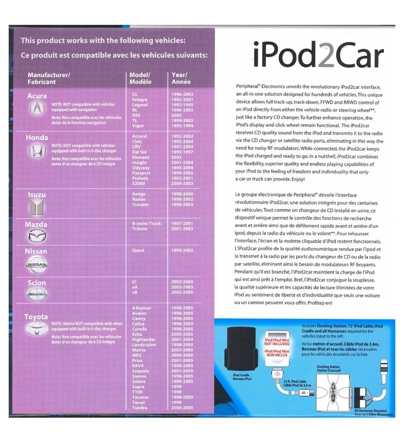
Peripheral Electronics iPod2car instruction manual

Park Safe
Park Safe Silent Witness SW001 manual

etrailer
etrailer e98874 quick start guide
Steelcraft
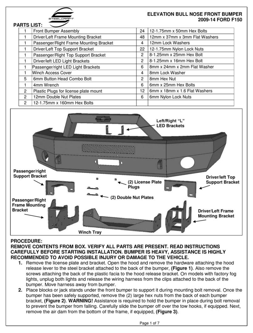
Steelcraft Elevation Bull Nose Front Bumper installation instructions
Air-Bus
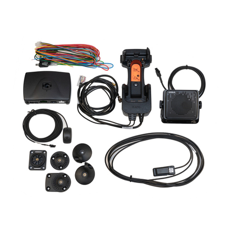
Air-Bus CARK-9 installation guide
Vanguard
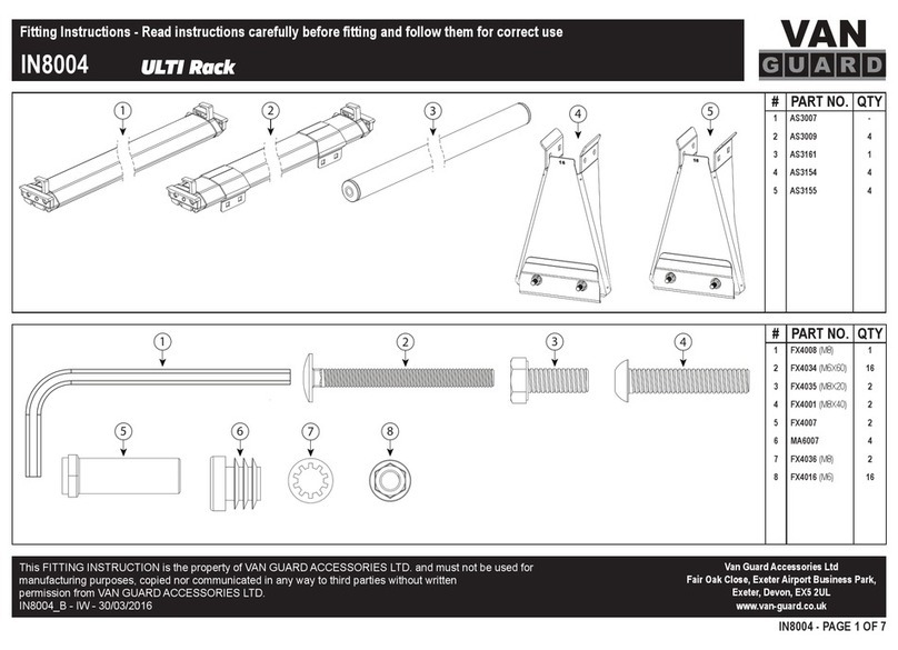
Vanguard VGUR-016 Fitting instructions
USASPEC
USASPEC PA15-FORD2 owner's manual
Etac
Etac Immedia AutoTurn Instructions for use
MRHANDSFREE
MRHANDSFREE Blue Eagle II owner's manual
