Digital Electronics Corporation Pro-Face PL-6900 Series User manual

PL-6900 Series
Panel Computer
User Manual
When printing out this PDF manual, since the printer setting can effect the
quality of the printout, be sure your printer’s quality setting is set to “High”.

i
Preface
PL-6900 Series User Manual
Preface
Digital’s PL-6900 series (PL) of Panel Computers are multipurpose factory
automation (FA) computers, which embody Digital’s latest, cost-effective
architecture. Before using the PL, read this manual thoroughly to familiarize
yourself with the PL’s operation procedures and functions.
1. It is forbidden to copy the contents of this manual in whole, or in part, without the per-
mission of the Digital Electronics Corporation.
2. The information in this manual is subject to change without notice.
3. This manual was written with care; however, if you should find any error or omissions,
please contact Digital Electronics and inform them of your findings.
4. Please be aware that we are not responsible for any damages resulting from the use of
our products, regardless of article 3 above.
Product names used in this manual are the trademarks of their respective manufacturers.
©Copyright 2000, Digital Electronics Corporation
MS-DOS®, Windows® 95 and Windows NT®are registered trademarks of the
Microsoft Corporation.
IBM®, and DOS®are registered trademarks of IBM.
NOTE:
ii
Preface
PL-6900 Series User Manual
This manual includes the following cautions concerning procedures that must be
followed to operate the PL correctly and safely. Prior to operating the PL, be sure to
read this manual and any related materials thoroughly to understand the correct opera-
tion and functions of this unit.
Safety Icons
To allow you to use the PL correctly, throughout this manual, the following icons
are provided next to operations requiring special attention. These icons are used to
describe the following situations:
Indicates situations where severe bodily
injury, death or major equipment damage
may occur.
Indicates situations where slight bodily
injury or machine damage can occur.
Caution
Warning
Essential Safety Precautions
• To avoid the possibility of an electric shock, be sure to
connect the power cord to the PL before connecting it to
the main power supply.
• A fire or electrical shock may occur if voltages used with
the PL are beyond the specified range. Be sure to use only
the specified voltage.
• Before opening the PL’s protective cover, be sure to turn
the unit’s power OFF. This is because the PL’s internal
parts carry high voltages.
• To avoid fires or electrical hazards, do not modify the PL in
any way.
• Do not create touch panel switches that are used to either
control or to ensure the safety of equipment and person-
nel. Mechanical switches, such as an emergency stop
switch, a deadman (two-handed) start switch, etc., must
be installed and operated via a separate control system.
WARNINGS

iii
Preface
PL-6900 Series User Manual
•After the PL’s backlight burns out, unlike the PL’s
“Standby Mode”, the touch panel is still active. If the op-
erator fails to notice that the backlight is burned out and
touches the panel, a potentially dangerous machine miss-
operation can occur.
If your PL's backlight suddenly turns OFF, use the following
steps to determine if the backlight is actually burned out.
1) If your PL is not set to "Standby Mode" and the screen
has gone blank, your backlight is burned out.
2) Or, if your PL is set to Standby Mode, but touching the
screen does not cause the display to reappear, your
backlight is burned out.
•If metal particles, water or other types of liquids contact
any of the PL’s internal parts, immediately turn the unit’s
power OFF, unplug the power cord, and contact either
your PL distributor or the Digital Electronics Corporation.
•Read and understand Chapter 4 “Installation and Wiring”
thoroughly in order to select an appropriate installation
location for the PL.
•Before either plugging in or unplugging a board or inter-
face connector, be sure to turn the PL’s power OFF.
WARNINGS
• Do not create touch panel switches which could possibly
endanger the safety of humans and equipment. This is due
to the possibility of a malfunction in the PL or its cable(s),
causing the output of a signal that could result in a major
accident. All of a system’s major, safety-related switches
should be designed to be operated separately from the PL.

iv
Preface
PL-6900 Series User Manual
WARNINGS
•To prevent a possible explosion, do not install the PL in
areas containing flammable gases.
•The PL is not appropriate for use with aircraft control
devices, aerospace equipment, central trunk data trans-
mission (communication) devices, nuclear power control
devices, or medical life support equipment, due to these
devices’ inherent requirements of extremely high levels of
safety and reliability.
•When using the PL with transportation vehicles (trains,
cars and ships), disaster and crime prevention devices,
various types of safety equipment, non-life support re-
lated medical devices, etc. redundant and/or fail-safe
system designs should be used to ensure the proper de-
gree of reliability and safety.
v
Preface
PL-6900 Series User Manual
•Do not push on the PL’s screen too strongly, with either
your finger or with a hard object. Excessive pressure can
scratch, crack or damage the screen. Also, do not use a
pointed object, such as a mechanical pencil or screw-
driver, to press any of the touch panel’s switches, since
they can damage the display.
•If the screen becomes dirty or smudged, moisten a soft
cloth with diluted neutral detergent, wring the cloth well,
and wipe the display. Do not use thinner or organic sol-
vents.
•Avoid exposing the PL to, or operating the PL in direct
sunlight, high temperatures and humidity, and in areas
where excessive dust and vibration will occur.
•Avoid using the PL in areas where sudden, extreme
changes in temperature can occur. This may cause con-
densation to form inside the unit, possibly leading to an
accident.
•To prevent the PL from overheating, be sure its air circula-
tion vents are clear and clean, and keep the unit’s opera-
tion area well-ventilated.
•Avoid operating or storing the PL near chemicals, or
where chemicals can come into contact with the unit.
When PL Hard Disk (HDD) data is lost:
•The Digital Electronics Corporation can not be held re-
sponsible or provide any compensation for damage(s)
caused by the loss of data stored in the PL’s hard disk
drive (HDD). It is therefore strongly suggested that all
important data and software be backed up regularly to an
external data backup device.
•Please be aware that the Digital Electronics Corporation
bears no responsibility for any damages resulting from the
customer’s application of this unit’s hardware or software.
CAUTIONS

vi
Preface
PL-6900 Series User Manual
The displayed color will look different when viewed from an angle outside the
specified view angle. This is also normal.
Displaying a single screen image for long periods of time can cause an afterimage
to remain on the screen. To correct this, turn the unit OFF for 5 to 10 minutes,
then ON again. This phenomenon is a common attribute of the LCDs, and is not
a defect. To prevent this effect, you can:
- use the Display OFF feature; if the same image is to be displayed for a long
period of time.
- change the screen display periodically to prevent the displaying of a single
image for a long period of time.
Notes on Handling the Hard Disk Drive
The Digital Electronics Corporation cannot take responsibility or provide any
compensation for damage(s) caused by the loss of data stored in the PL-6900
series’ hard disk drive (HDD). It is therefore strongly suggested that all impor-
tant data and software be backed up regularly to an external data backup device.
Please be aware that the Digital Electronics Corporation bears no responsibility
for any damages resulting from the customer’s application of this unit’s hard-
ware or software.
Please be aware that the Digital Electronics Corporation will not provide com-
pensation for any damages occurring as a result of problems with this unit’s
software or hardware.
Since the PL’s hard disk drive (HDD) is a consumable item, i.e. it has a finite
usage lifetime, be sure to back up its data frequently and perform regular main-
tenance.
To prevent damage to file data, be sure to shut down the PL’s OS before turning
OFF the main power.

vii
Preface
PL-6900 Series User Manual
Table of Contents
Preface
Preface .......................................................................................................................... i
Essential Safety Precautions........................................................................................ ii
Table of Contents....................................................................................................... vii
Prior to Using the PL................................................................................................... x
Information Symbols .................................................................................................. xi
Package Contents ...................................................................................................... xii
PL-6900 Series Features........................................................................................... xiii
UL/cUL Application Notes ...................................................................................... xiv
CE Marking ............................................................................................................... xv
Chapter 1 Overview
1-1 System Configuration ...................................................................................... 1-1
1-2 Options .............................................................................................................. 1-2
1-3 PL Series Panel Types ......................................................................................1-5
Chapter 2 Specifications
2-1 General Specifications .................................................................................... 2-1
2-1-1 Electrical Specifications ....................................................................... 2-1
2-1-2 Environment Specifications.................................................................. 2-2
2-1-3 Dimensions ........................................................................................... 2-3
2-2 Performance Specifications............................................................................ 2-4
2-2-1 Performance Specifications .................................................................. 2-4
2-2-2 Display Functions ................................................................................. 2-5
2-2-3 Expansion Slots .................................................................................... 2-5
2-2-4 Clock(RTC) Accuracy .......................................................................... 2-5
2-3 Interface Specifications .................................................................................. 2-6
2-3-1 Printer Interface .................................................................................... 2-6
2-3-2 Keyboard Interface ............................................................................... 2-6
2-3-3 Mouse Interface .................................................................................... 2-6
2-3-4 RS-232C Interface (COM1/COM2/COM3) ......................................... 2-7
2-3-5 RAS Interface ....................................................................................... 2-7
2-4 PL External Features...................................................................................... 2-9
2-5 PL Dimensions............................................................................................... 2-11
2-5-1 PL-6900T General Dimensions .......................................................... 2-11
2-5-2 PL-6901T General Dimensions .......................................................... 2-12
2-5-3 Full Sized Cover Attachment Dimensions ......................................... 2-13
2-5-4 Installation Slot Dimensions............................................................... 2-14

viii
Preface
PL-6900 Series User Manual
Chapter 3 Installing Optional Units and Expansion Boards
3-1 Installing Options and Expansion Boards ..................................................... 3-1
3-1-1 Removing the rear maintenance cover ................................................. 3-2
3-1-2 Installing the DIM Module (PL-EM220 / PL-EM230)......................... 3-4
3-1-3 Installing the FDD Unit (PL-FD200).................................................... 3-5
3-1-4 Installing the FDD Unit (PL-FD210).................................................... 3-6
3-1-5 Removing/Installing the HDD unit (PL-HD220) ................................. 3-8
3-1-6 Installing an Expansion Board.............................................................. 3-9
3-1-7 Connecting the CD-ROM Unit (PL-DK200) ..................................... 3-10
3-1-8 Removing the Cooling Fan Unit......................................................... 3-11
Chapter 4 Installation and Wiring
4-1 Installation Cautions........................................................................................ 4-1
4-2 Installing the PL ............................................................................................... 4-3
4-2-1 Installation Procedures ......................................................................... 4-3
4-3 Wiring the PL ................................................................................................... 4-6
4-3-1 Connecting the Power Cord.................................................................. 4-6
4-3-2 Power Supply Cautions ........................................................................ 4-8
4-3-3 Grounding Cautions.............................................................................. 4-9
4-3-4 Cautions When Connecting I/O Signal Lines....................................... 4-9
Chapter 5 System Setup
5-1 Setup Procedures............................................................................................. 5-1
5-2 System Parameters.......................................................................................... 5-2
5-2-1 STANDARD CMOS SETUP ............................................................... 5-2
5-2-2 BIOS FEATURES SETUP ................................................................... 5-4
5-2-3 CHIPSET FEATURES SETUP ............................................................ 5-6
5-2-4 POWER MANAGEMENT SETUP ..................................................... 5-8
5-2-5 PNP/PCI CONFIGURATION SETUP ............................................... 5-10
5-2-6 SYSTEM MONITOR UTILITY ........................................................ 5-12
5-2-7 INTEGRATED PERIPHERALS ........................................................ 5-14
5-2-8 IDE HDD AUTO DETECTION SETUP ........................................... 5-16
Chapter 6 OS Setup
6-1 Setting Up Your PL OS .................................................................................. 6-1
6-1-1 Touch Panel Device Driver Settings ..................................................... 6-2
Chapter 7 Maintenance and Inspection
7-1 Regular Cleaning ............................................................................................ 7-1
7-1-1 Cleaning the Display............................................................................. 7-1
7-1-2 Moisture Resistant Gasket Replacement .............................................. 7-2
7-2 Cleaning the Filter .......................................................................................... 7-2

ix
Preface
PL-6900 Series User Manual
7-3 Changing the PL Backlight............................................................................ 7-4
7-4 Periodic Check................................................................................................ 7-9
Appendix
1 Hardware Configuration............................................................................... A-1
1-1 I/O Mapping ........................................................................................ A-1
1-2 Memory Mapping ................................................................................ A-2
1-3 IRQ Mapping ....................................................................................... A-3
2 RAS Feature ................................................................................................... A-4
2-1 PL’s RAS Features ............................................................................... A-4
2-2 RAS Feature Details ............................................................................ A-5
2-3 RAS Feature Overview........................................................................ A-9
Index

x
Preface
PL-6900 Series User Manual
The PL’s hard disk is designed for use with the Windows®95, WindowsNT®4.0
or later OS. The Mirror Disk unit will operate only with the WindowsNT®4.0
operating system. Other operating systems do not support this driver software,
etc.
For system setup and OS installation, a PS/2 type keyboard is necessary.
When using Windows®95/WindowsNT®4.0, be sure to install the PL-6900 Series
Driver & Utility Disk’s Display Driver (For installation procedures, see the disk’s
readme files (README.95E or README.NTE).
For information on the PL’s bundled utility software, see the README file on
the Driver & Utility Disk.
Since the PL’s hard disk drive (HDD) is a consumable item, i.e. it has a finite
usage lifetime, be sure to back up its data frequently and perform regular main-
tenance.
After turning the PL OFF, be sure to wait at least 5 seconds before turning ON
again. If the unit is stated within 5 seconds, it may not start up correctly.
Prior To Using the PL
Prior to actual use, be sure to setup your PL as follows.
Turn PL ON Refer to 4-3 Wiring the PL
Setup System Refer to Chapter 5 System Setup
Refer to the OS maker’s Installation Manual.
After completing the hardware setup, before any data or applications can be placed on
the drive, the OS (Windows®or MS-DOS®, etc.) must be used to initialize the HDD and
create partitions. For details concerning these procedures, refer to the OS maker’s
installation manual.
Install the OS

xi
Preface
PL-6900 Series User Manual
Information Symbols
This manual uses the following icons:
Indicates a warning or a product limitation. Be sure to follow the instruc-
tions given with this icon to insure the safe operation of the PL.
Contains additional or useful information.
Indicates terms or items that require further explanation. See the footnote
on that page.
Indicates pages containing related information.
Indicates steps used to accomplish a given task. Be sure to follow these
steps in the order they are written.
*
1), 2)

xii
Preface
PL-6900 Series User Manual
Package Contents
The PL package should include the following items:
Be careful when install-
ing the PL not to dam-
age the built-in HDD
Power Cord
PL Unit
(PL-6900T/PL-6901T)
This cord is designed only for AC100/115V
use. Any other voltage will require a differ-
ent cable.
Installation Brackets (8)
Floppy Disks (3)
“PL-X900 Series Driver & Utility Disk”
CD-ROM (1)
Contains PL-6900 Series
User Manual (This Manual)*
Your PL unit package will also contain an Installation Guide for your
built-in HDD unit.
Be sure to check that guide’s package contents.
If your PL contains a built-in HDD
Instruction
Guide
Instruction Guide
(English1/Japanese1)

xiii
Preface
PL-6900 Series User Manual
PL-6900 Series Features
The PL-6900 series displays are equipped with the following features:
The Latest, High-Performance Architecture
Designed around the AMD-K6®-2 333 MHz CPU, the PL utilizes the type of high
performance architecture that offers you superior compatibility. Add to this unri-
valled support of the Windows®95/Windows NT®and other operating systems.
Bright 12.1" LCD with a Wide Viewing Angle
The PL’s large 12.1-inch 800 x 600 dot TFT LCD display offers excellent vis-
ibility and brightness.
•Digital’s top of the line TFT color LCD model allows you to create detailed
and powerful visual images, with excellent brightness, a wide viewing angle,
and a display capable of 260,000 colors.
Easy Front Panel Installation
The PL is designed to be installed easily into the front of any panel or device. It
is also rugged enough for use in harsh, industrial environments, such as those
found in the factory automation industries and boasts an IP65f rating.
High Resolution, Analog-Resistance-Film Touch Panel
Standard equipment with the PL is a high resolution 1024 x 1024 touch panel.
Also, the Windows®95 mouse emulation utility provides mouse-like function-
ality and pointer control.
Highly Expandable
The PL units consist of two types; a 2 slot type (with 1 PCI bus also available),
and a 4 slot type (with 2 PCI buses available). These slots can accommodate
both Digital’s own optional boards as well as other commercially available ex-
pansion boards.
Digital also offers a wide variety of optional products, such as a -5/-12V DC
power unit, DIM memory modules, etc.

xiv
Preface
PL-6900 Series User Manual
UL/cUL Application Notes
The PL690*-T4* is (c)UL 1950 recognized product. (UL File No. E171486). Please pay spe-
cial attention to the following instructions when applying for UL/cUL approval for machinery
which includes any of these PL units.
The PL conforms as a component to the following standards:
UL 1950, Third Edition, dated March 1,1998 (Standard for Safety of Information Technology Equip-
ment, including Electrical Business Equipment)
CSA-C22.2 No. 950-95 (Standard for Safety of Information Technology Equipment, including Electrical
Business Equipment)
PL6900-T4* (UL Registration Model No.: 2780054-04)
PL6901-T4* (UL Registration Model No.: 2780054-03)
-Equipment with a PL mounted in it requires UL/cUL evaluation for the combination of the
PL and equipment.
- The PL must be used as a built-in component of an end-use product.
- Use the PL indoors only.
-When connecting the PL’s power cable, be sure to use a cable that is appropriate for the
current and voltage used and that has conductive wires that are 0.75 mm2or larger.
-With an end-use product which includes the PL, be sure to place the PL’s Power cut-off
switch as the disconnect device where the unit’s operator can easily reach it.
-Danger of explosion if backup battery is incorrectly replaced. Replaced only with same or
equivalent type recommended by the manufacturer. Dispose of used batteries according to
the manufacturer’s instructions.
-Be sure the unit the PL is built into uses a UL1950 compatible equipment structure.

xv
Preface
PL-6900 Series User Manual
CE Marking
The PL690*-T4* units are CE marked, EMC compliant products.
<Complies with the following Standards>
Safety
EN60950
EMI (EN50081-2)
EN55011 group1 (Class A)
EMS (EN50082-2)
EN61000-4-2, EN61000-4-3, EN61000-4-4,
EN61000-4-6, EN61000-4-8, ENV50204
If following requirements are not met, the PL may fail to meet EN60950 standard requirements.
Equipment with a PL mounted in it requires UL/cUL evaluation for the combination of the
PL and equipment.
The PL must be used as a built-in component of an end-use product.
Use the PL indoors only.
When connecting the PL’s power cable, be sure to use a cable that is appropriate for the
current and voltage used and that has conductive wires that are 0.75 mm2or larger.
When installing the PL in a metal panel or cabinet, be sure to place the PL’s Power discon-
nect device (cut-off switch) where the unit’s operator can easily reach it.
There is a danger of explosion if the backup battery is incorrectly replaced. This battery
should be replaced only with same or equivalent type recommended by the manufacturer.
Dispose of used batteries according to the manufacturer’s instructions.
Be sure the cabinet/enclosure the PL is built into uses an EN60950 approved sheet steel structure.

xvi
Preface
PL-6900 Series User Manual
MEMO
1 - 1
PL-6900 Series User Manual
Overview
1-1 System Configuration
Chapter
1Overview
1-1 System Configuration
1-2 Options
1-3 PL Series Panel Types
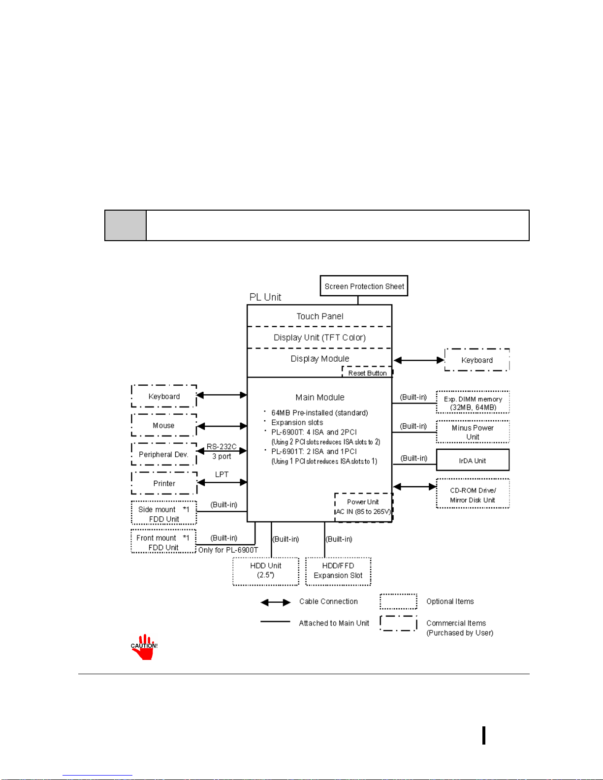
The following chart shows the range of peripheral items connected to the PL.
• Only one FDD unit can be used at one time, i.e. either the front panel’s
FDD, or the main unit’s FDD.
*1 Only one FDD unit can be used at one time, i.e. either the front panel’s FDD, or the main
unit’s FDD.
1 - 2 PL-6900 Series User Manual
Overview
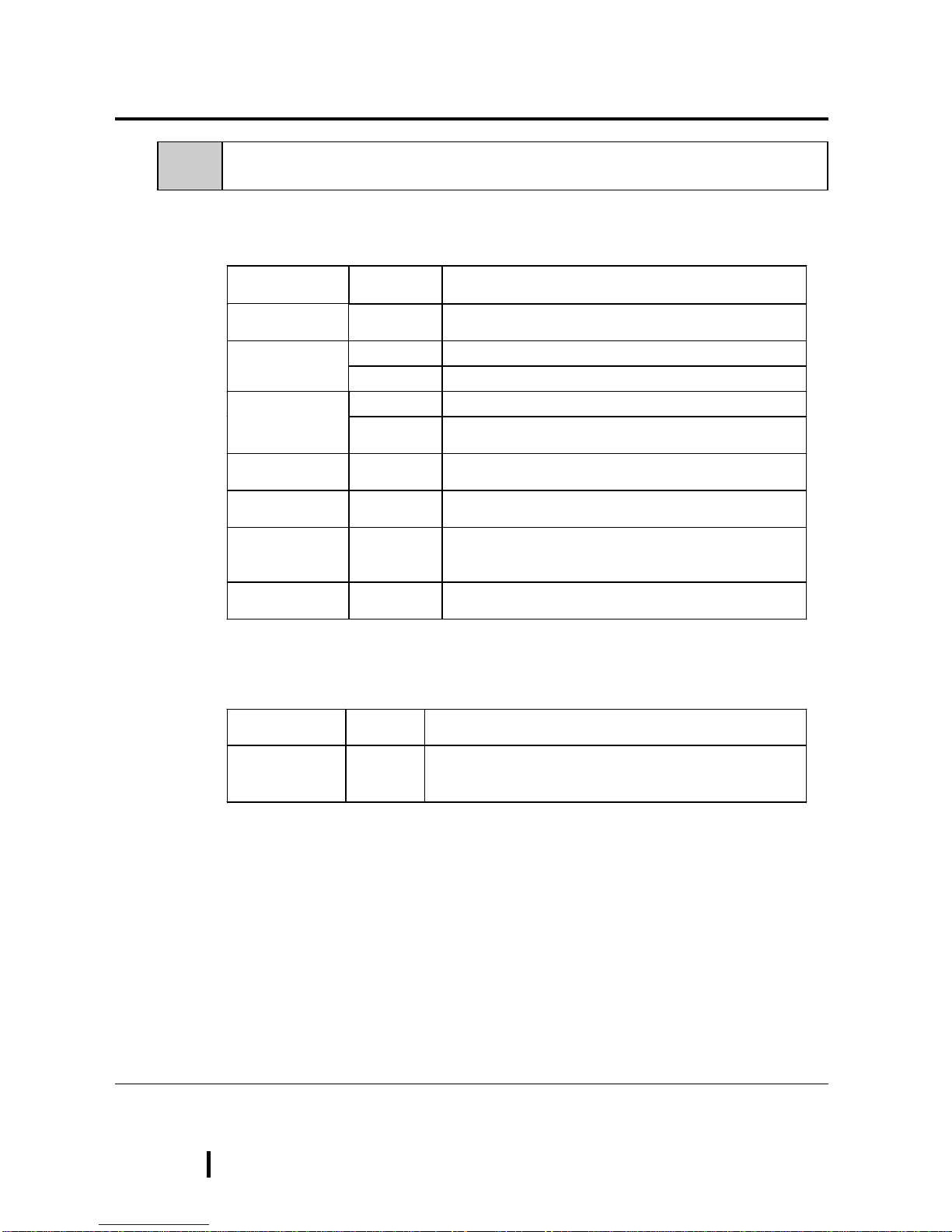
Name Model
number Description
LAN Board DAX-IET02 NE2000 compatible board. Provides connectors for
10BASE-5, 10BASE-2 and 10BASE-T.
PL-EM220 SDRAM (DIMM) Provides 32MB of memoryDIM Module
PL-EM230 SDRAM (DIMM) Provides 64MB of memory
PL-FD200 *1IBM PC Compatible 3.5” FDD unit (Attaches to side slot)FDD Unit
PL-FD210 *1IBM PC Compatible 3.5” FDD unit (Attaches to front slot)
Only for PL-6900T
-5V/-12V Power
Unit PL-PW100 Provides –5V and –12V power to expansion slots. Can
provide a total of 200mA of current (sum of both slots).
FFD Unit
(Flash File Disk) PL-FF200 Flash File Disk Provides 20MB of memory, connected to
IDE I / F. Used as HDD.
CD-ROM Unit PL-DK200 IDE (ATAPI) compliant CD-ROM drive unit
– for development and maintenance use.
(special connection cable is included with unit)
Mirror Disk Unit PL-MD200-H
U01 IDE compliant mirror disk unit without OS
Name Model
number Description
Screen
Protection Sheet PL-CS100 Disposable overlay sheets for display face protection and
stain resistance. Touch panel senses User’s touch
through sheet. (5 sheets/set)
1-2 Options
The following table provides a list of optional products for the PL
Expansion Options
Accessories
*1 Both the PL-FD200 and the PL-FD210 cannot be used at the same time.

1 - 3
PL-6900 Series User Manual
Overview
Name Model
number Description
Mounting
Brackets GP070-AT
01 Used to install the PL into a panel or cabinet. Same as
original equipment brackets. (4 brackets/set)
Moisture
Resistant Gasket PL-WS100 Used to prevent moisture from entering into the PL’s case
from the front face. Same as original equipment gasket.
HDD Unit PL-HD220 2.5”HDD unit (10.0GB or larger - contains no pre-installed
OS
Mirror Disk Unit
Replacement HDD PL-MD200-
MD01 Mirror Disk Unit’s replacement HDD (1).
PL-FC200 Attached when ISA bus full sized board is used in the
expansion slot. (for PL-6901T)
Full-sized cover PL-FC210 Attached when ISA bus full sized board is used in the
expansion slot. (for PL-6900T)
Backlight GP675T-BL
00-MS Spare Backlight for maintenance.
Maintenance Options
•Since the PL’s hard disk drive (HDD) is a consumable item, i.e. it has a
finite usage lifetime, be sure to back up its data frequently and perform
regular maintenance.
•Both the PL-FD200 and the PL-FD210 cannot be used at the same time.
Product Description Installation Area
PCI/ISA Bus
compatible
board
In all PL-6900 series units, slot 1 can accommodate
boards up to 163mm wide. Slot 2 (slots 2, 3 and 4 for
PL-6900T) can accommodate boards up to 250mm
wide.
■
■■
■All PL-6900 series slot heights are 122mm. When
using the full-sized cover, be sure to use boards
that are no more than 338mm wide and 122mm
high in slot 2.
■
■■
■The height of the devices attached to the face of
an expansion board can be, for slot 1 (slots 1 and
4 for PL-6900T), up to 13mm, and for slot 2 (slots
2 and 3 for PL-6900T), up to 18mm.
Into the PL's expan-
sion slots.
Commercially Available Products
^
^
Width
Height
Attaching Direction
Table of contents
Other Digital Electronics Corporation Desktop manuals

 user manual")
 user manual")


