CHAPTER
4
4.1
4.1.1
4.1.2
4.2
4.2.1
4.2.1.1
4.2.1.2
4.2.2
4.2.3
4.2.4
4.3
4.3.1
4.3.2
4.3.3
4.3.4
CHAPTER
5
5.1
5.2
Figure
No.
1-1
2-1
2-2
2{3
244
3-1
3-2
3-3
3-4
3-5
3-6
3-7
3-8
3-9
3-10
3-11
3-12
3-13
3-14
3-15
3-16
3-17
3-18
CONTENTS
(Cont)
Page
PRINCIPLES
OF
OPERATION
LVOl
Printer/Plotter
.....................................
4-1
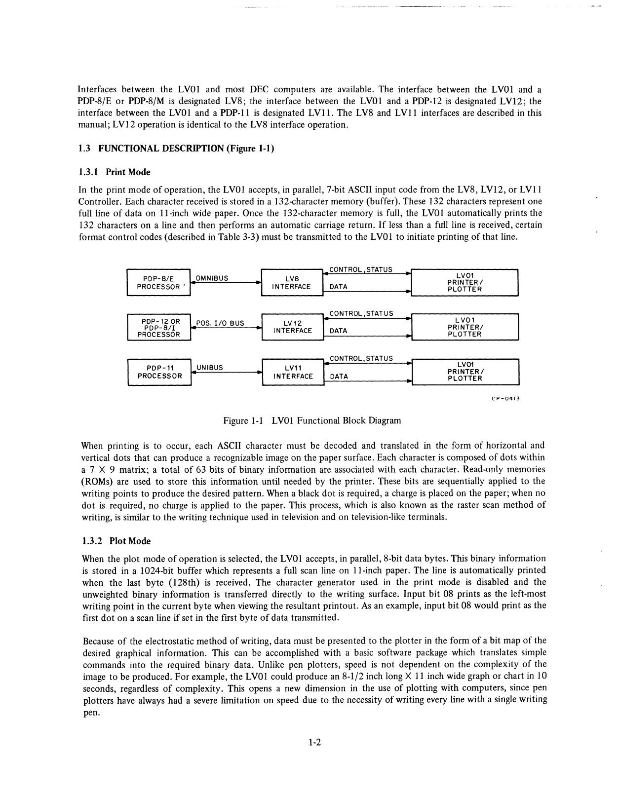
General
Operation
...................................
4-1
Electrostatic
Writing
Technique
............................
4-2
LVll
Detailed
Description
..................................
4-2
Address
Selection
Logic
................................
4-2
Address
Inputs
..................................
4-3
Outputs
.....................................
4-5
Interrupt
Control
...................................
4-6
Data
Register
Logic
..................................
4-7
Printer
Control
Logic
.................................
4-7
LV8
Detailed
Description
..................................
4-9
IOT
Decoding
.....................................
4-10
Printer
Control
.....................................
4-11
Data
Register
......................................
4-12
Interrupt
and
Skip
Control
...............................
4-12
MAINTENANCE
Inspection
..........................................
5-1
Diagnostics
..........................................
5-1
ILLUSTRATIONS
Title
Page
LVOl
Functional
Block
Diagram
...............................
1-2
Damage
Inspection
......................................
2-1
Back
Panel
Removed
.....................................
2-2
Platen
Raised
View
......................................
2-3
Removing
Packing
Material
.................................
2-3
Paper
Removal
........................................
3-2
Inserting
Cross
in
Roll
Paper
.................................
3-2
Inserting
Roll
Paper
.....................................
33
Paper
Pulled
Out
.......................................
3-3
Paper
Transport
Module
...................................
3-4
Control
Panel
........................................
3-4
Fanfold
Paper
Guide
.....................................
3-5
Paper
Stacking
Insert
.....................................
3-5
Paper
Supply
Compartment
.................................
3-5
‘Fan’
the
Paper
to
Loosen
the
Sheets
............................
3-7
Position
of
Stack
for
Fanfold
Operation
...........................
3-8
Loading
Paper
over
the
Paper
Guide
Assembly
........................
3-8
Positioning
the
Paper
Left-to-Right
on
the
Paper
Roller
...................
3-9
Paper
Loaded
and
Top
Casting
Closed
............................
3-9
Location
of
Paper
Receiver
Basket
..............................
3—9
Inserting
Tubes
in
Toner
Bottle
...............................
3-10
Toner
and
Concentrate
Bottles
Installed
...........................
3-10
Control
and
Status
Register
Bit
Assignments
.........................
3-15
iv