Digital Guard Dawg iKEY-M User manual

iKey-M
Passive Entry & Keyless Ignition for
2010-2014 Mustang's


iKEY-M
Passive Keyless Entry and Push Button Start
For 2010 – 2014 Mustangs
Thank you for purchasing the iKEY-M Passive Keyless Entry and
Push Button Start kit for your 2010-2014 Ford Mustang.
You will love the luxurious convenience of Passive Keyless Entry & Push Button Start!
The kit will add the same Keyless Access and Keyless Ignition operation found on the latest
model Mustang’s to your 2010 – 2014 model. It’s never been simpler to add the latest in
RFID Keyless technology to your Mustang, This exciting new product provides you with
everything you’ll need for a painless, easy to follow DIY installation that will make your
keys, “A thing of the Past!
The iKey-M uses advanced RFID (Radio Frequency Identification) technology from Texas
Instruments®, to provide you the ultimate in convenience and protection. No more
frustration from searching or fumbling around with keys or remotes to enter and start
your car.
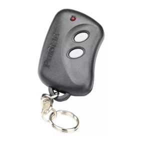
You simply place one of the systems OEM styled RFID key fobs in your pocket, as you
approach your Mustang, your doors will automatically unlock and the systems elegant
Start Button will illuminate. Climb inside and you’re ready to go, with just a push of the
Start Button your engine roars to life!
Exit and you just walk away . . . . As you leave the systems frequency range, your doors
will automatically lock and iKey-M’s advanced two-stage security system will self-arm
leaving your Mustang securely protected. With the iKEY-M it’s Impossible to forget to
protect your vehicle!
Made with high quality factory grade components, the iKey-M includes an OEM style Key
Fob, lighted factory style Start Button and Emergency backup vehicle access card. Our
innovative plug & play “T” harness uses factory connectors to interface directly with your
Mustangs Ignition system and allows even someone with modest installation experience
to dress up their pony with this exciting accessory.
Losing Your Keys Never Felt So Good!

Table of Contents
Preface
A. Tools You Will Need
B. System Overview
C. Before you begin:
Key-M Install Overview
1 Cut and Program Red Key
- 1a: Cut Spare key blank
- 1b: Program Spare key to vehicle
2 Assemble Bypass Module
-2a Separate Transponder from key blade
-2b Mount Transponder into Bypass module
3 Remove Vehicle Panels
-3a Remove Upper Steering Wheel Shroud
-3b Remove Plastic Knee Panel
-3c Remove Lower Steering Wheel Shroud
-3d Remove Metal Knee Panel
4 Access Ignition Harness Connector
-4a locate Ignition Connector
-4b The Wrong Connector
-4c Release Ignition Connector
5 Making Primary Module Connections
-5a Velcro Modules Together
-5b Plug in Primary Module Connectors 1-4
6 Make Battery Connections
-6a Run Power wire
-6b Connections to Battery
7 Mount System Antennas
-7a Antenna Types
-7b Mounting the Emergency Access Antenna
-7c Mounting the Proximity Antenna’s
8 Mount Immobilizer Bypass Ring
9 Make Brake Switch Connection
10 Make Ignition Connections
11 Make ACC Connections at SJB “ Smart Junction Box”
-11a Run the Accessory Harness to the SJB
-11b Understanding the SJB
-11c Making Connections at the SJB
12 Initial Start Button Mounting
13 Mounting the Status LED

- Standard Pliers (for closing quick connects)
- Small Hacksaw or Dremel Drill ( to cut Key Blank)
- Wire Terminal crimpers / Kline Style
- Wire strippers
- Small Hook Tool to remove vehicle Panels
- Socket Ratchet
- 9/32 socket
- 8 mm socket
- 7mm socket
- 10 mm socket
- T20 Torx driver
- 8mm or 5/16th Drill bit
- Flash light or portable shop light
- QTips and Rubbing Alcohol
14 Finalizing Connections and Mounting System Modules
-14a Final Connections
-14b Mounting System Modules
15 System Pre-Test
-15a Connect Battery +12V
-15b Key Fob Test
-15c Testing Flow Chart
16 Finalizing your Start Button Installation
17 Final System Testing
Section A. Tools You Will Need:

Section B System Overview Primary Components
Start your vehicle and check that all your Mustangs current features work correctly. Did your car start
easily? Is the battery strong? Check if both door locks work from the power switch? Do your parking
lights all work? Does your trunk pop? Now roll down your windows, then turn everything back off.
All good?
You’re ready to start your install!
Section C Before you begin:

STEP 1. Cut and Program Spare Key
1a: Cut Spare key blank
Included in kit is a Spare Mustang Key Blank. You will be using this blank
to release the steering column lock as well as activate the Bypass module
of your system. Before you begin installing your system, you will need to
have the Ignition Key blank cut to fit your vehicles ignition switch. Most
any hardware store can do this for a couple dollars.
Please read and understand the entire procedure before you begin.
1. Insert the first currently programmed coded key into the ignition.
2. Turn the ignition from the 1 (LOCK) position to the 3 (RUN) position.
Keep the ignition in the 3 (RUN) position for at least three seconds, but no more than 10 seconds.
3. Turn the ignition to the 1 (LOCK) position and remove the first coded key from the ignition.
4. Within ten seconds of turning the ignition to the 1 (LOCK) position, insert the second currently coded
key.
5. Turn the ignition from the 1 (LOCK) position to the 3 (RUN) position.
Keep the ignition in the 3 (RUN) position for at least three seconds, but no more than 10 seconds.
6. Turn the ignition to the 1 (LOCK) position and remove the second currently coded key from the
ignition.
7. Within twenty seconds of turning the ignition to the 1 (LOCK) position and removing the currently
programmed coded key, insert the Spare un-programmed key into the ignition.
8. Turn the ignition from the 1 (LOCK) position to the 3 (RUN) position.
Keep the ignition in the 3 (RUN) position for at least six seconds.
9. Remove the newly programmed coded Spare key from the ignition. The theft indicator light will
illuminate for three seconds and then go out to indicate successful programming. (PIC 3)
10. TEST: Use the new Spare key to start your vehicle. If the key has been successfully programmed
your engine will start.
1b: Program Spare key to vehicle
Next, follow the instructions below to program the new Spare key to the vehicles computer.
You can also check out this YouTube video that shows the programming process:
https://www.youtube.com/watch?v=Kz6935L6XFI
*** NOTE: YOU MUST CURRENTLY HAVE TWO WORKING / PROGRAMMED IGNITION KEYS TO
PREFORM THIS PROCEDURE. If you do not have two working/programmed keys, you will have to take
this remote key to a dealer or locksmith for programming.
* If you have a 2013 “Shelby” Mustang please call us before preforming programming.

2A: Separate Transponder chip from key blade
Using a Dremel drill or other cutting tool; cut the blade of the spare key off right where the shaft meets
the body. Use a file to remove any rough edges.
2B: Mount Transponder Key Head into Bypass Module
Attach a small square of double sided tape to the head of the spare key and remove the protective film
from the tape.
Next, remove the cover of the Bypass module by removing the 4 small Phillips screws on the back.
Next, insert the spare key head into the Bypass module as shown with the sticky tape side down. Press
firmly the key head in place to assure the head is secure.
Lastly, replace the Bypass Module cover.
STEP 2. Assemble Bypass Module
Overview: Inside the head of the every Ford key is a “RFID Transponder” this is a Radio Frequency ID
chip with a unique code. Your vehicle computer must read this code before it will allow your vehicle to
start. During Step 1, we programmed the code of the Spare key into your vehicles computer. Now we will
separate the head of the key with the RFID Chip inside and place it into the systems “Bypass Module”.
This module will send the ID code to your vehicles computer when you push the Start Button of your
iKEY-M system.
You will use the cut KEY BLADE later in Step 13

STEP 3. Remove Vehicle Panels
To gain access to your Mustangs ignition connector and key switch you will need to remove the four
following interior panels:
3a. Remove Upper Steering Wheel Shroud.
Begin by first lowering the tilt wheel to its bottom position, (pic1). Grab shroud by outer edges and
firmly pull up (Pic2). Pull back and up to remove shroud from wheel (pic3).

3c Remove Lower Steering Wheel
Shroud
To release the lower steering wheel
shroud remove the three T20 Torx
screws.
The two front screws are short and
the back screw is long. The back screw
is a bit harder to locate.
Look to the far back of the panel
opening.
3d Remove Metal Knee Panel
The metal Knee Panel is held in place
by 4 bolts. Two 10mm on each side
of the top and two 8mm on each
side of the bottom. Remove bolts
and lift off panel.
3b Remove Plastic Knee Panel
Begin by removing the two 9/32” screws,
(one on each side of panel) (pics 2 & 3).
Next, pull out firmly to release panel.
Note: on the left side of panel there is a
corner piece that slips behind the left side
pillar molding. (pic4). Carefully side the
panel sideways to release.

Step 4: Access Ignition Harness Connector
4a Locate Ignition Connector
The Ignition Connector is attached to the back of the Ignition Switch. It can be accessed by reaching in
the opening behind where the lower steering wheel shroud was attached. It faces the firewall and can
be seen easier by looking up under the dash.
4b The WRONG Connector
There is a similar looking connector
that is to the left of the Ignition switch.
It is not attached to the Ignition switch.
This is the Wrong Connector!
4c Unplug the Ignition Connector
To release the Ignition Connector from the Ignition Switch Housing you will need to depress the locking
tab on the top of the connector. Grab the harness and connector and pull out firmly. Sometimes it helps
to wiggle connector as you pull.

Step 6: Make Battery Connections
A-Place the Modules and Wiring Harness on the driver’s side floor. Locate the Red “Power” and Black
“Ground” wires of the main harness.
B- Open the hood. On the right side you will see a 1” rubber Grommet. Remove the grommet and drill a
3/8” hole in the center.
C- Feed both wires through the firewall opening then through the grommet hole. Snap the grommet
back into place.
D - Use zipties to secure Power and Ground wires along the top of the firewall.
E - Use crimpers to crimp a “U” connector to each wire. Then attach the Black wire to the Battery (-) .
DO
NOT ATTACH THE RED TO THE BATTERY + AT THIS TIME! LEAVE LOOSE UNTIL INSTALL IS COMPLETE.
Step 5: Primary Module Connections
Step 5: Make Main Harness Connections
Begin by unspooling the Main Harness on the driver floor area.
5A - Make connections C2, C3, C4 and C5 from the Main Harness to iKey Module as shown.
5B - Make connection C5 from the Main Harness to the Bypass Module.
5C - Use velcro squares to attach modules together.

Step 7: Mount System Antennas
7a - Types of system Antenna’s
There are three types of system Antenna’s.
#1 The Bypass Antenna plugs into the 556U Bypass module and goes around the vehicles ignition switch.
#2 The Proximity Antenna’s read the Transponder Key Fobs and activates the system as you approach your vehicle.
#3 The Emergency Access Antenna reads the systems Emergency Backup Card which allow you to operate your
vehicle in the event you were to lose your Transponder Fobs.
7b - Mounting the Emergency Backup Antenna
The Emergency Backup Antenna allows you to access and start your vehicle even if you were to lose your
Transponder Fobs. The doors will unlock and the system will activate by holding one of the Emergency Backup
Cards within 3” from the antenna for 5 seconds. The Emergency Backup Antenna should be mounted on the
dash near the VIN plate where the dash meets the windshield. To run the wire for the Antenna you will need to
pull back the top of the vinyl panel covering the driver’s side “A” Pillar. The “A” Pillar panel is held on by 4 clips
that will pop out. ( Pic 1 ) It is usually not necessary to completely remove the “A” Pillar panel. It just needs
to be pulled back far enough to feed the Antenna wires behind the panel. ( Pic 2 ) Feed the connector end of the
Emergency Access Antenna wire behind the panel and out the other side. ( Pic 3 ).
Move the wire back and forth, as
if you are flossing ( Pic 4 ) while
sliding it down the panel until the
Emergency Access Antenna is at the
level of the dash.
( Pic 5 ). Remove the sticky back
tape from the Antenna and position
it next to VIN plate as shown.
This will allow you to place the
Emergency Backup Card within 3”
of the Antenna should you need to
access the vehicle without a
system
Transponder Fob. Leave the connector
end of the wire hanging down at the
bottom of the “A” Pillar in the driver’s
door jam. You should have 2 feet or
more of remaining wire. You will plug
the Emergency Bypass Antenna into
the module in step 14, "Making Final
Connections".

7c - Mounting the Primary Proximity Antenna’s
The Proximity Antenna’s read the Transponder key fobs as you approach the vehicle. There are two
Proximity Antenna's and a "Y" harness that the antennas plug into. One antenna is mounted on at the top
of each side of the vehicles windshield. Remove the sticky back tape from the back of each antenna and
place them at the top of both sides of the windshield.
Next, connect the Antennas to "Y" harness, using the long wire of the "Y" harness for the passangers side
antenna and the short wire to the drivers side. Tuck the wire in behind where the headliner meets the
windshield using the foam squares provided to hide the wire and hold in place. Next as before, run the
remaing side of the "Y" harness behind the "A" piller. Start at the top and bring it out the bottom where it
can later in step 14 be plugged into the iKey module.

Step 8: Mount Immobilizer Bypass Antenna Ring
The 556U and Bypass antenna ring allow your vehicle’s security system to receive an authorization code
without a key being present. You will be mounting the Bypass ring around the ignition switch cylinder
and plugging it into the 556U module. Begin by wrapping the Bypass ring around the lock cylinder in
front of the black part of the cylinder. You will have a small amount of excess bypass ring wire. Use a
zip-tie to secure any excess bypass ring wire. Use another zip-tie to secure the Bypass ring in place. It is
also a good idea to use a small amount of contact adhesive or silocone to perminately secure the ring in
place. Next, Feed the wires from the ring under the dash and secure with a Zip-tie. (* Note the wires on
the ring are delicate; handle carefully being sure not to put strain onto these wires. Plug the Bypass
Antenna connector into the 556U bypass module Lastly, plug in the "C6" connector (5 slot / 3 wire)
from the main wiring harness into the 556U Bypass module. Note: When routing the Antenna or other
wires DO NOT ATTACH TO THE CROSSMENBER UNDER THE STEERING WHEEL.

Step 9: Make Brake Switch Connection
The Key uses a +12V signal from your Brake Switch to know when you want to start and turn off the
vehicle’s Ignition. The Brake Switch is located under the dash at the top of the Brake arm. (Pic 1 ).
To release the Brake Switch, Twist it counter clockwise and pull down. ( Pic 2 / Pic 3 ).
On the back of the switch is a connector with 4 wires in it. (Pic 4 ). Attach a Red “Quick Connect” to the
Purple / White wire of the switch (Pic 5 ). Next, plug in the Purple / White Brake wire labeled “BRAKE”
from the systems Main harness ( Pic 6 ).
Step 10: Make Ignition Connections
To make the Ignition connections, take the connector you unplugged from the Mustang’s Ignition switch
and firmly plug it into Connector “C1” from the iKEY-M Main harness. Be sure the connectors “Snap and
lock” next use a ziptie to secure the connectors up under the dash.

Step 11: Make Accessory Connections at SJB (Smart Junction Box)
SJB - INSTALLATION
The next group of connections you will make, are
the wires that operate the Mustang’s Accessory
functions such as Door lock & unlock, Trunk pop,
Parking light flash and Factory security arm & disarm.
All these connections are made at the vehicle’s
SBJ or “Smart Junction Box”. This box is located
behind the passenger side kick panel.
11b – Understanding the SJB
Remove the passenger vinyl
kick panel cover by pulling
from the back forward. Behind
it you will see the Mustang’s
Smart Junction Box. It has
several multi-pin connectors
and can look intimidating at
first glance. But don’t worry,
this is fairly easy, All but one
of your connections are made
at a single location, (the #1
Connector). With only one
remaining connection made at
Connector #2 (Pic 3 ).
11a Run the Accessory side of the harness to SJB
The Accessory harness is the harness that has 6 Red
Spade connectors labeled 1 – 6 (Pic 1 ). Begin by
running this harness from the driver’s floor area to the
passenger’s side kick panel. Run the harness behind the
center console and come out just above the door of the
passenger’s side kick panel (Pic 2 ).

11c – Making Accessory Connections
For ease of access and to give yourself some room to work, it is easiest to unplug the connectors from
the SJB before making connections to them. Begin by releasing the #1 Connector. Simply pull
the clip from the bottom of the connector upwards to release the locking clip of connector
(Pic1 ). It often helps to wiggle the connector a bit to release it. (Pic 2 ). Once you have unplugged
Connector #1, peel back any electrical tape around the harness so you have 2” inches of wire exposed
to work with (Pic 2 ).
The Connections you will be making are listed on the Accessory Table below:
Notes prior to making connections;
The wire colors of both the Accessory Harness and the Factory Wires will match. * except If you are
installing a mustang Convertible( the Trunk may be different.) (See wire #5). Make connections to wires
aproximately 1 in. below the factory connector. Do not pull on factory wires when making connections.
Make sure your Quick Connection “Snap” closed.
*** If you are unfamiliar with how to use a 3M® “T” Tap Connectors see instructions in using
T-Tap connectors, see YouTube Video: https://www.youtube.com/watch?v=ikZZBmvFEho

Begin with connection #1 the Blue / Green Lock wire. Separate the wire from the others and attach
a Quick Connect. Be sure the Quick Connect is snaped closed. Next plug the spade connector from the
#1 Blue / Green wire in the Accessory harness into the Quick Connect. Be sure the Spade connector is
full inserted. ( Pic 3 / Pic 4 ) OK, good job, just a few more to go!
Next, move on to SJB Connector #2 . Only one connection is made here, the Parking Lights. To release the
connector there is a tab on the side that needs to be depressed, then simply wiggle and
pull it out. ( Pic 5 ). Make your #6 Purple / White Accessory wire connection and then replace the SJB
Connector. ( Pic 6 ). Use Zip-ties to clean up wiring and tuck wires away behind floor panels. Lastly replace
the kick panel cover.
11c – Making Accessory Connections "Continued"
Now move on to the next wire the #2 Yellow / Purple unlock wire. Repeate the process. Continue one
wire at a time until all wires 1 – 5 are connected. ***NOTE: On some year Mustangs when you get to the
#4 Green / Purple Factory Disarm wire you may find two Green / Purple wires in the #1 Connector. One
in the middle of the connector and one on the end edge of the connector. Use the one in the middle
of the connector. Once all connections are complete, Plug the SJB #1 Connector back in and lock into
place.

Step 12: Initial Start Button Mounting
Next, ( Pic 3 ). Position the Lower Steering Wheel Shroud for re-attaching. But prior to reattaching the
Lower Steering Wheel Shroud, remove the rubber trim ring that surrounds the key switch hole and also
run the wire for the Start Button between the key switch cylinder and the ignition switch hole. Leave the
Start button hanging loosely and unattached as shown in (Pic 4). Plug the Start Button connector end into
the Key Module. Next, you want to insert the Cut key blank you prepared in Step #2 into the lock cylinder.
( Pic 5) Insert the key shaft into the key hole and turn the key to the RUN position. ( Pic 6) Lastly, move
the lower shroud panel into place and replace all three T20 Torx screws you previously removed, (The two
short screws go in front and one long screw in back).
Step 12: Initial Start Button Mounting
*** Should you desire to mount your start button elsewhere, almost any surface will work fine using the 3M
mounting tape placed on the back of the button. If you are mounting your Start button in another location
other than over the existing key switch, be sure to remove the 4 Phillips screws from the metal mounting
plate from the rear of the Start button. Also be sure and clean the surface before mounting with some
rubbing alcohol first.
The instructions below describe how to mount the Start Button over the Mustang’s existing Key Switch. In
this section you will perform the initial placement of the Start Button, which will include running the start
button wire and making its connection to the Key module and re-attaching the lower steering panel. Before
finalizing the mounting of the Start Button, you will want to perform some initial system function tests while
the connections you made for the immobilizer bypass ring are still easily accessible. Begin by bending up the
4 mounting arms of the start button as shown in Pic "A & B"Next, remove the white protective film from the
back of the 3M Adhesive tape disk and mount it to the Start Button. Pic "C"
.
Table of contents
Other Digital Guard Dawg Remote Starter manuals
