Digital Lightwave ASA 312 User manual

Front 1
Front 2
GENERAL SAFETY GUIDELINES
The following safety precautions are provided to avoid injury and prevent damage to this product or
any products connected to it during normal operation. Only qualified maintenance personnel should
perform service procedures.
•Use Proper Power Cord. To avoid fire hazard, use only the power cord specified for this
instrument.
•Avoid Electric Overload. This unit is designed to be powered from 90–132 and 180–260 VAC, 47-
63 Hz, 60 watts. To avoid electric shock, fire hazard, or damage to the instrument, do not apply a
higher voltage.
•Ground the Instrument. The ASA 312 is grounded through the grounding conductor of the power
cord. To avoid electric shock, the grounding conductor must be connected to earth ground. Before
making connections to the input or output terminals of the instrument, ensure that the product is
properly grounded.
•Do Not Operate in Hazardous Conditions. To avoid injury or fire hazard, do not operate this
instrument in wet, damp, or other hazardous conditions. Do not operate this instrument in an
explosive atmosphere.
•Wear Eye Protection. Because there is potential danger from the laser light source, certain
precautions should be followed. Users should never stare into unterminated connectors or broken
fibers. In addition, fiber cables and interfaces should always be handled as if they were emitting
laser light. Always leave protective covers on optical connectors to prevent damage and laser
emissions. CAUTION: Use of controls, adjustments, or procedures other than those specified
herein may result in hazardous radiation exposure.
•Replacing the Battery. The ASA 312 uses a lithium battery located in the service access area not
accessible to customers. To avoid damaging the unit, do not ,under any circumstances, attempt to
replace the lithium battery. Return the unit to Digital Lightwave, Inc. for battery replacement.
WARNING: Danger of explosion exists if the battery is replaced incorrectly. Do not, under any
circumstances, attempt to replace the lithium battery.
Copyright © 2000 Digital Lightwave, Inc.
All rights reserved. This publication, or parts thereof, may not be
reproduced in any form, by any method, for any purpose. For
conditions of use and permission to use these materials for publication
in other than the English language, contact Digital Lightwave, Inc.
Digital Lightwave, Inc. reserves the right to revise and improve its
product as it sees fit. This publication describes the state of this
product at the time of its publication and may not represent the
product at all times in the future.
Technical Support
Technical Support is available by calling toll free
1.877.929.HELP (4357) or 1.800.548.9283.
Digital Lightwave, Inc.
15550 Lightwave Drive • Clearwater , Florida 33760 United States
Telephone: 727.442.6677 • Fax: 727.442.5660
Toll Free: 800.548.9283 or 877.275.3445
info@lightwave.com • http://www.lightwave.com
Front 3
How To
Use
General
Info
Printing SONET DS3 DS1 ATM E1
Getting Started
Card-1
Software Version
Card-2
Selection
Card-9
DS3 Mapped
Card-12
Looped
(Test Pattern)
Card-17
Looped
(Test Pattern)
Card-22
Function Settings
Card-27
75-to-120 Ohm
Adapter Interface
Card-35
Glossary
(Back of Guide)
Signal Level
Card-3
Saving Results
Card-10
VT1.5 Mapped
Card-13
Monitoring
(Live Traffic)
Card-18
Monitoring
(Live Traffic)
Card-23
ATM Over OC3c
Card-28
Looped
(Test Pattern)
Card-36
Error Insertion
Card-4
Print Saved
Results
Card-11
STS-1 Mapped
Card-14
M-13 Mapped
Card-19
Loop Codes
Card-24
ATM Over OC12c
Card-29
Monitoring
(Live Traffic)
Card-37
Saving a Setup
Card-5
OC3c/OC12c
(Concatenated)
Card-15
FEAC Codes
Card-20
DS0 Scan
Monitor
Card-25
Add/Edit 1 VCC
Card-30
E1 M13 Mapped
Card-38
Recall a Setup
Card-6
Switch to Protect
Card-16
Zoom Mode
Card-21
Zoom Mode
Card-26
Add VCCs
Card-31
Timed Test
Card-7
VCC Scan/Add
Card-32
File Transfer
Card-8
Errors/Alarms
Card-33
Quick Setup
Document No. CO 003179B Rev B
Q.O.S. (Delay)
Card-34
Front 4
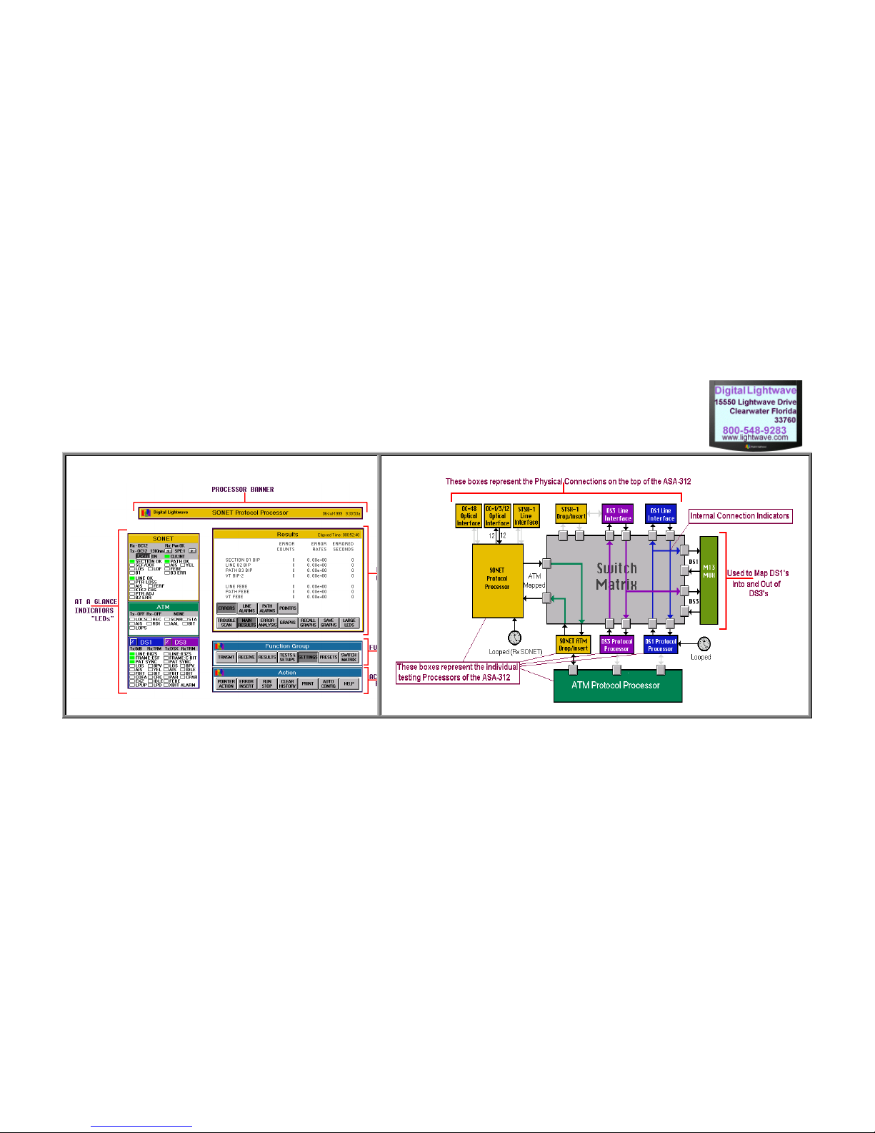
Anatomy of the ASA 312 Touch Screen Anatomy of the ASA-312 Switch Matrix Screen
Front 5
Getting
Started
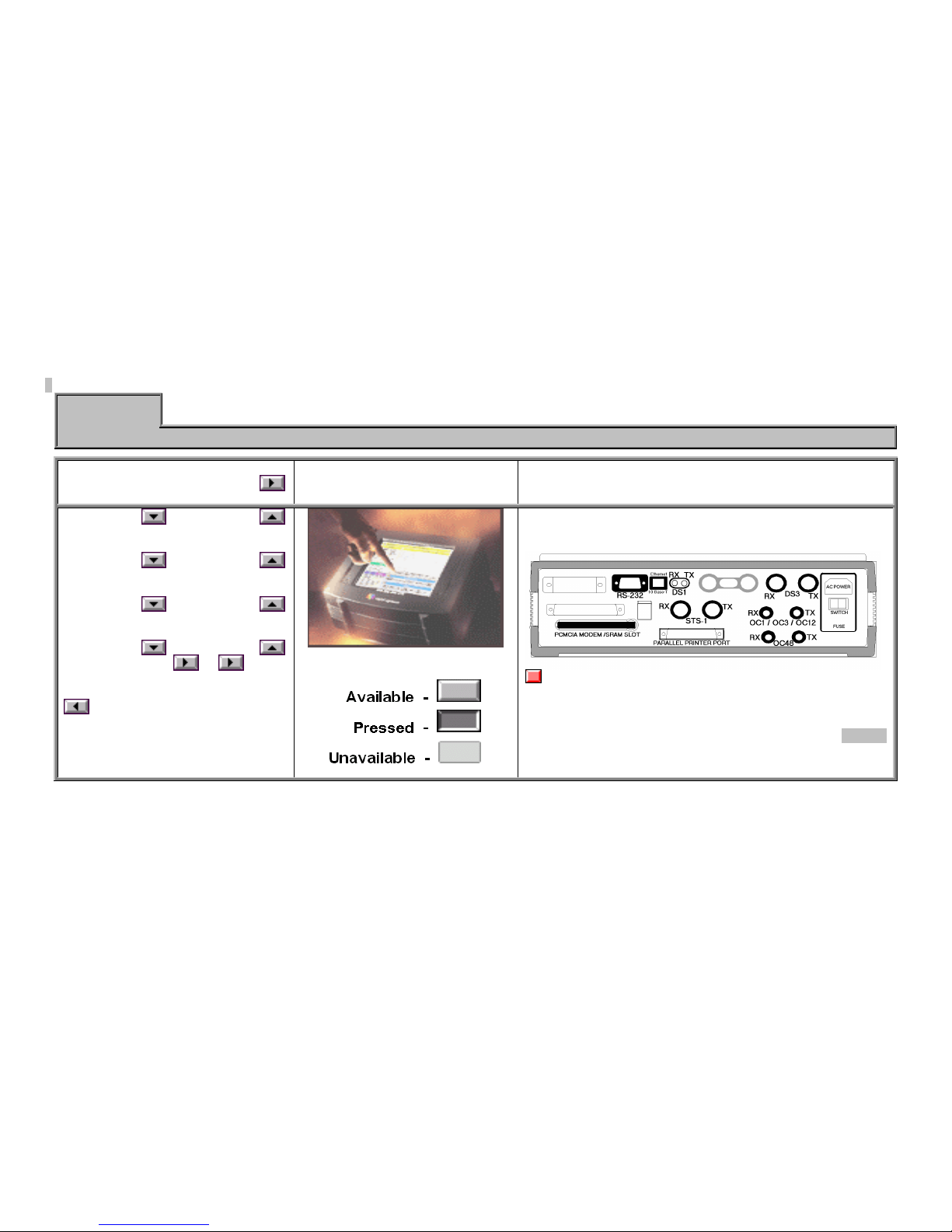
How To Use Quick Setup
1. Read a selected card.
Direction of flow is down, and
then across.
2. Press each button on your test
set. Releasing your finger will
activate the button.
3. Connect any appropriate cables to the top of the test set.
Additional information will
be on the back side of the
previous card to the left.
Button Types:
The Top Side of the ASA 312
Note:
For more detailed information, refer to the ASA 312 and RAM
User's Guide.
Card - 1
Front 6
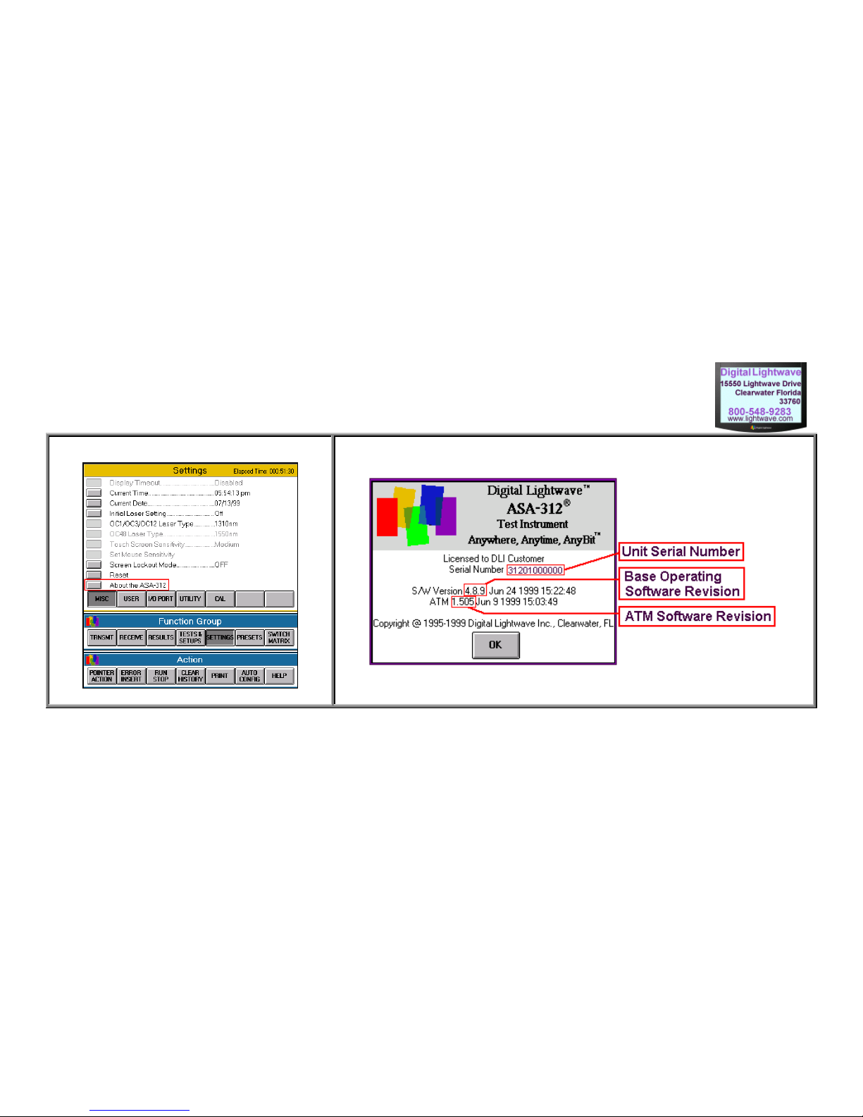
Miscellaneous Screen "About the ASA-312" Screen
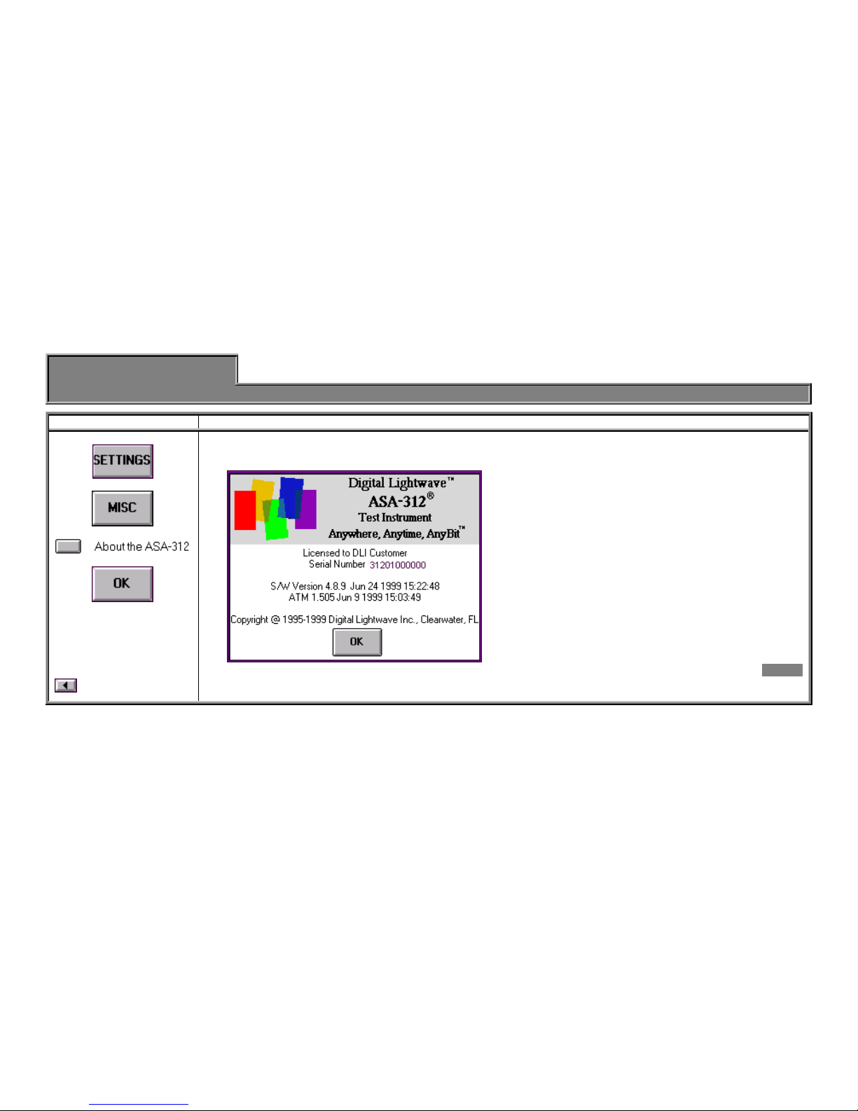
Front 7
Software
Version
General Info Quick Setup
1. Select The "About the ASA 312" Screen
Additional Info
The ASA 312 test set operates similar to a portable PC
running on a DOS-based platform.
The unit's operating software has two parts: Base and
ATM (if the ATM feature is installed). "S / W" version is
the Base version.
The ASA 312 software can be replaced with more
current releases that may contain operational
improvements and added functionality. The Quick Setup
Guide will attempt to reflect the latest software version;
however, there may be slight operational differences
between your test set and the Quick Setup Guide.
Consult Digital Lightwave's Customer Technical Support
for information regarding current software versions and
upgrading procedures.
Card - 2
Front 8
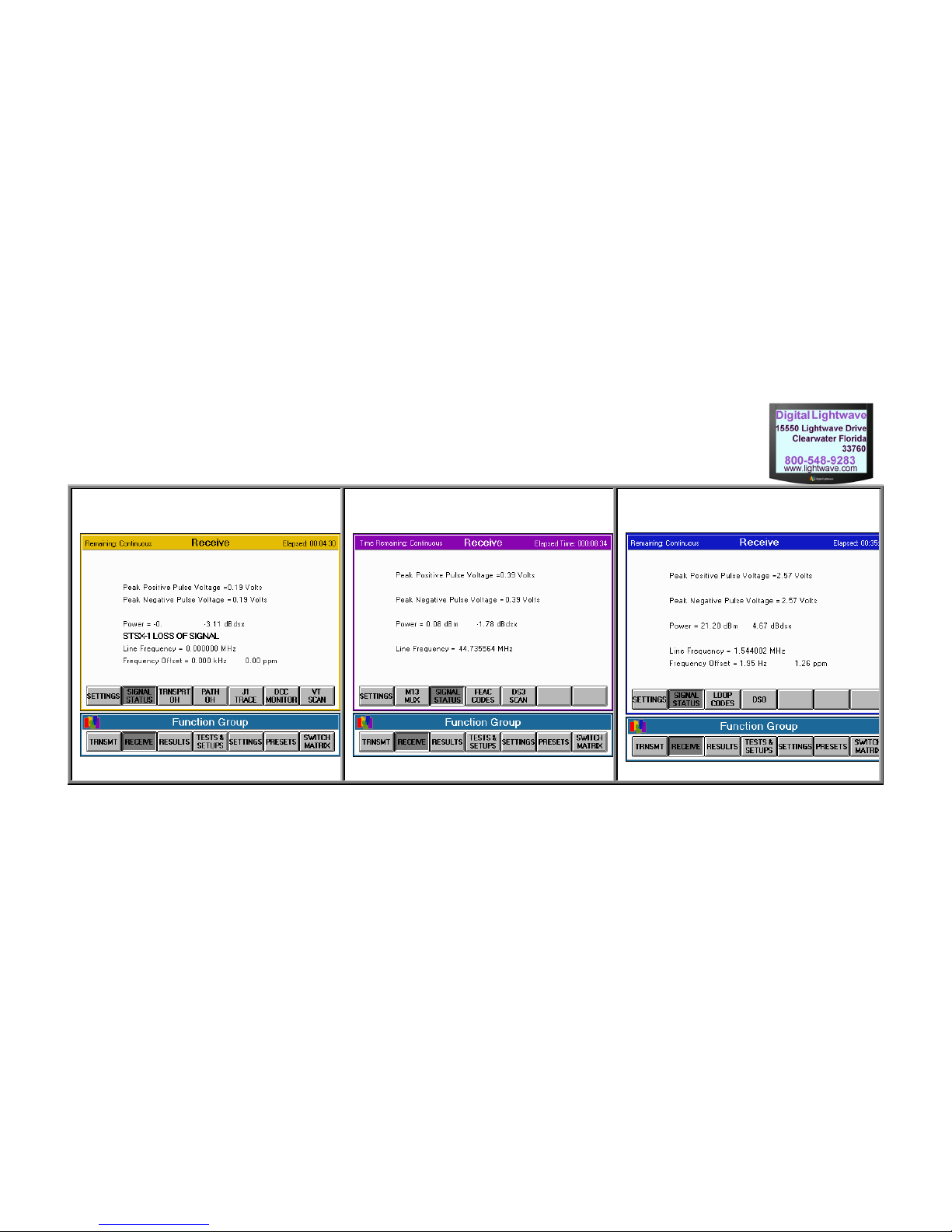
SONET Receive Signal Status DS3 Receive Signal Status DS1 Receive Signal Status

Front 9
Signal Level
General Info Measurement Quick Setup
1. Select a processor. 2. Press STS-1 Specs OC-1, 3, 12 Specs OC-48 Specs DS3 Specs DS1 Specs
-or-
-or-
Note: The test set
must have a "signal
source" connected.
Additional Info
Under
Function
Group,
Then
Peak
positive and
negative
voltage range:
± 0.31Vp to
± 1.2Vp
Frequency
Range:
51.84 MHz, ±
50 ppm
(Receive)
Optical Power
0 to -26 dBm,
± 1.5 dB
Line Frequency
Range:
N x 51.84 MHz,
± 50 ppm
(Receive)
Optical Power
0 to -26 dBm,
± 1.5 dBm
Line Frequency
Range:
N x 51.84 MHz,
(2,488.32 MHz)
± 50 ppm
(Receive)
Peak
positive and negative
voltage range:
± 0.31Vp to ±1.2Vp
Terminated
+ 6 to -26 dB
relative to DSX3
Monitor
-15 to -30 dB
relative to DSX3
Line Frequency
Range:
44.736 MHz,
±200 ppm
(Receive)
Peak
positive and negative
voltage range
±0.1Vp to ±7Vp
Terminated
+ 6 to -30 dBdsx
22.532 to -13.468
dBm
Monitor
0 to -36 dBdsx
16.532to -19.468 dBm
Bridge
0 to -36 dBdsx
16.532 to -19.468
dBm
Line Frequency
Range:
1.544 MHz, ±200ppm
Card - 3
Front 10
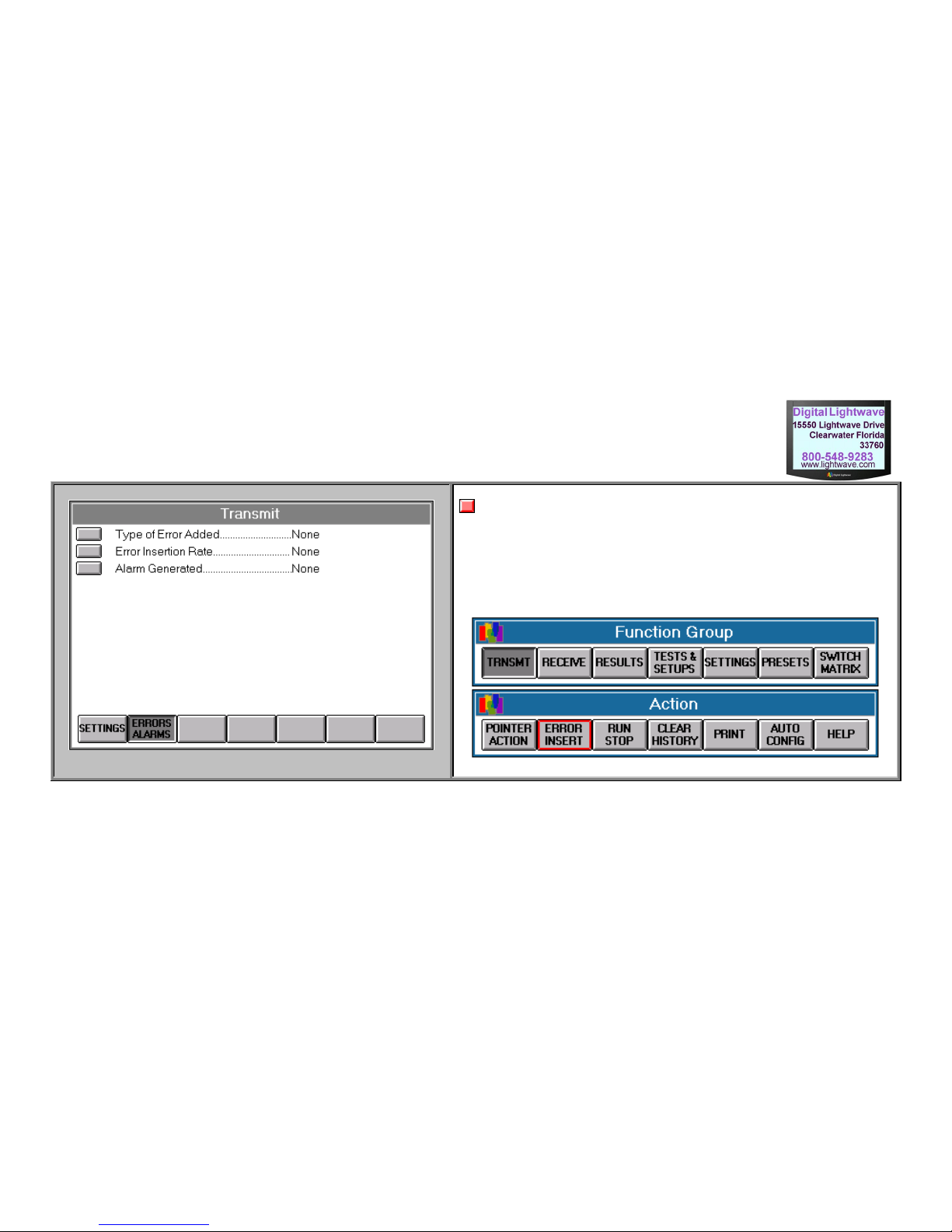
Transmit Error Screen
Notes:
In order to perform Error Insertion, the ASA 312 must currently be running an
"error-free" test.
This instruction card assumes that the ASA 312 is configured to perform the
desired test, and is either looped on itself, connected to a circuit that is looped
somewhere, or is performing an "end-to-end" test with a compatible test set.
Front 11
Error Insertion
General Info Quick Setup
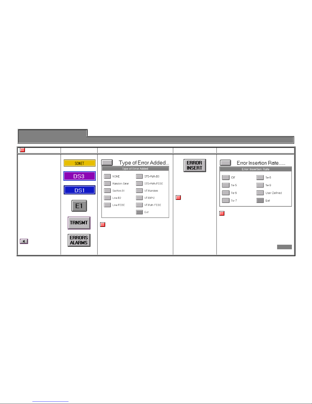
Note 1. Select Proc. 2. Select Error Type. 3. Single Errors 4. Automatic Errors
This instruction card
assumes that the
ASA 312 is
configured to
perform the desired
test, and is either
looped on itself,
connected to a
circuit that is looped
somewhere, or is
performing an "end-
to-end" test with a
compatible test set.
Additional Info
-or-
-or-
-or-
Note: The above selection is only
an example. It has choices that relate
to SONET; however, the selected
processor will have choices specific to
that processor.
(Located in the
Action row on the
bottom of the
screen.)
Important Note:
Major setting
changes such as
Mapping will reset
the error type back
to "none." When the
error type is set to
"none," this button
will not function.
Note:
The above selection is only an
example. It has choices that relate to
SONET; however, the selected
processor will have choices specific to
that processor. Alarm types may have
different rate choices as well.
Card - 4

Front 12
Test & Setups Screen [Save/Recall Setup Section] Save Setup

Front 13
Saving Setup
General Info Quick Setup
1. Configure unit. 2. Press 3. Select disk and name
file.
4. Enter a file description. 5. Choose type of setup. 6. Save it.
Note:
Ensure all settings in
the ASA 312 are
configured for the
type of test setup
that you would like
to save for future
use.
Additional Info
Set to "Flash."
Enter a file name.
(8 characters maximum)
(optional)
Enter a description of the file
(25 characters maximum).
You can choose to save the setup
of the current processor or ALL of
the setups of the test set.
Card - 5

Front 14
Test & Setups Screen [Save/Recall Setup Section] Recall Setup
Front 15
Recall Setup
General Info Quick Setup
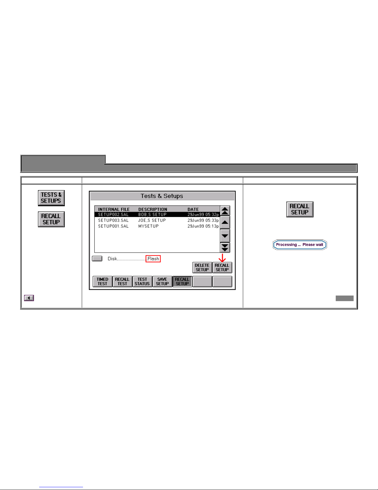
1. Select 2. Select the file by name and description. 3. Choose type of setup.
Additional Info
Press
(Button located to the far right.)
(Wait for completion.)
Card - 6

Front 16
Test & Setups Screen [Save/Recall Setup Section]

Front 17
Timed Test
General Info Quick Setup
1. Select printer. 2. Select proc. 3. Press 4. Press 5. Select 6. Run the test.
See the Printing
section for more
information.
Important Note:
Printing operation
should be
successfully tested
before performing a
timed test in order to
verify printer settings
and cabling.
Additional Info
-or-
-or-
-or-
The User Defined screen allows for a
more specific time duration.
Press
Select up to four traps.
Chose Type, Event, and Threshold
for each trap.
Press
Card - 7

Front 18
Important Note:
Once a port is selected, other buttons will not respond until the port is
restored to "None."
Additional Required Settings:
For Direct connect, check [I/O Port] / [Serial] / [Baud Rate].
For External modem, check [I/O Port] / [Serial] / [Baud Rate].
Make sure the modem is powered on and connected to the port before
selecting the port.
For PCMCIA modem, check [I/O Port] / [PCMCIA] / [Baud Rate].
Insert the card into the slot before selecting the port (listen for the "beep
beep" when inserting it).
For LAN connection, check [ I/O Port ] / [ Ethernet ] / [ IP Address ]
(normal modular network cable required or crossover if connecting
directly to a PC NIC card).

Front 19
File Transfer
General Info (Receiving) Quick Setup
1. Notes 2. Connect the port. 3. Select the Transfer Port.
File Transfer: A utility
function of the ASA 312
that allows files to be
transferred into or out of
the unit. The standard
file transfer protocol, "Y-
Modem", is used.
This is the primary
method for upgrading
the operational software
of the ASA 312.
Additional Info
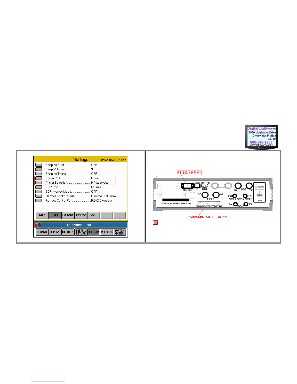
You can connect the ASA 312 to:
PC Direct: Use the RS232 port ("null modem" cable or adapter
required).
External Modem: Use the RS232 port (normal 9-pin to 25-pin
modem cable required).
Internal Modem: Use the PCMCIA slot (PCMCIA modem
required).
LAN (10Base/T): Use the Ethernet port (normal modular network
cable required, or crossover if connecting directly to PC NIC card).
From any processor screen, press:
Card - 8
Front 20
User Selection Screen Printer Ports
Note: Not all ASA 312s have a parallel port.
Other manuals for ASA 312
1
Table of contents


