AEMC OX7102-CII User manual

99-MAN 100341 – v1 – 09/09
OX-CII SERIES
Portable Oscilloscopes
100MHz 2-channel OX 7102-CII
100MHz 4-channel OX 7104-CII
User Manual
AEMC®Instruments d.b.a. Chauvin Arnoux®, Inc.
15 Faraday Drive • Dover, NH 03820
Tel. (603) 749-6434 • Fax: (603) 742-2346

General Instructions
I - 2 SCOPIX Oscilloscopes
Contents
General instructions Chapter I
General...................................................................................................4
Software updating................................................................................. 6
Description of the instrument Chapter II
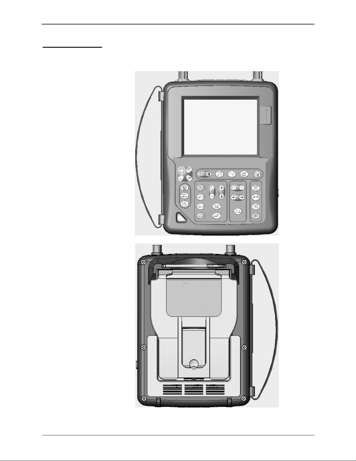
Presentation ......................................................................................... 7
Views......................................................................................................8
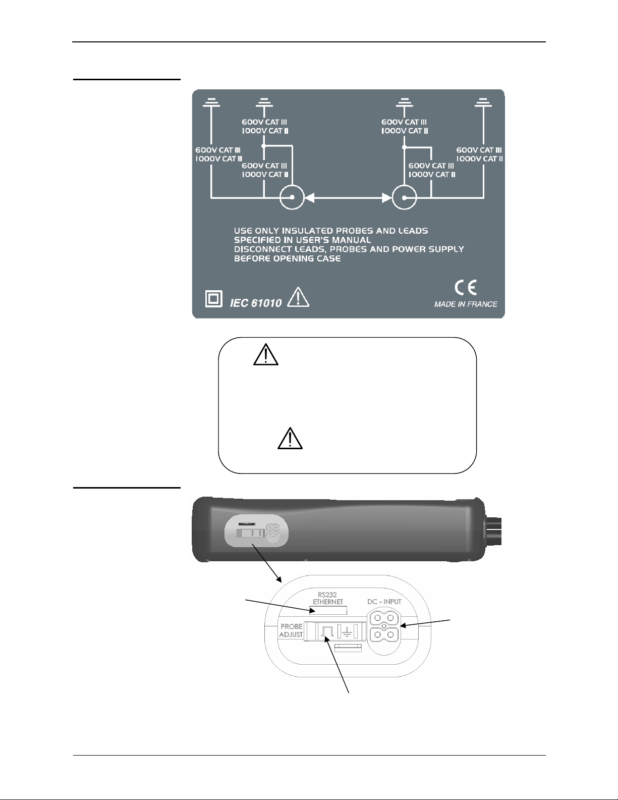
Terminal Boards..................................................................................12
Activation............................................................................................. 14
Battery.................................................................................................. 15
Using the menus.................................................................................17
Network................................................................................................17
Description of Accessories Chapter III
HX0061 ............................................................................................... 21
HX0063 ............................................................................................... 21
PROBIX ...............................................................................................22
HX0030..................................................................................23
HX0031.................................................................................. 24
HX0032.................................................................................. 25
HX0033.................................................................................. 26
HX0034.................................................................................. 27
HX0035.................................................................................. 28
HX0036.................................................................................. 29
HX0072.................................................................................. 30
HX0073.................................................................................. 31
Recommandations for use.................................................................... 33
Oscilloscope Mode Chapter IV
Keys......................................................................................................35
Display ................................................................................................. 40
Menus
"Vertical" menu.................................47
"Trigger" menu.................................59
"Horizontal" menu.................................70
"Display" menu.................................75
"Measurement" menu.................................77
"Memory" menu.................................82
"Utilities" menu.................................85
"Help" menu.................................91
Multimeter Mode Chapter V
Keys......................................................................................................94
Display ................................................................................................. 96
Menus...................................................................................................99
"Vertical" menu...............................100
"Trigger" menu...............................102
"Horizontal" menu...............................103
"Display" menu...............................103
"Measurement" menu...............................105
"Memory" menu...............................107
"Utilities" menu...............................107
"Help" menu...............................107

General Instructions
SCOPIX Oscilloscopes I - 3
Harmonic Analysis Mode Chapter VI
Display ...............................................................................................109
Menus
"Vertical" menu...............................113
"Horizontal" menu...............................115
"Display" menu...............................116
"Measure" menu...............................116
"Memory" menu...............................117
"Utilities" menu...............................117
"Help" menu...............................117
Recorder Mode Chapter VII
Keys....................................................................................................119
Display ...............................................................................................122
Menus
"Vertical" menu...............................130
"Trigger" menu...............................131
"Horizontal" menu...............................136
"Display" menu...............................137
"Measurement" menu...............................139
"Memory" menu...............................140
" Utilities" menu...............................143
"Help" menu...............................145
Web Server Chapitre VIII
Using the WEB Server......................................................................147
Applications Chapter IX
Display of the calibration signal ..........................................................157
Automatic measurements...................................................................159
Cursor measurements ........................................................................160
Phase offset measurement with cursor ..............................................160
Automatic phase measurement..........................................................160
Manual phase measurement .............................................................. 161
Videosignal display .............................................................................161
Examination of a specific TV line........................................................163
Automatic measurement in “Harmonic Analysis” Mode......................164
“ROLL” Mode display of slow phenomena..........................................166
Min/Max Acquisition............................................................................167
Measurement in “Multimeter” Mode....................................................169
Measurement in “Recorder” Mode......................................................170
ETHERNET network application examples........................................174
File transfer.........................................................................................174
Hard copy on network printer .............................................................175
Installation of a FTP server.................................................................176
Installation of a LPD server.................................................................180
Technical Characteristics Chapter X
Specifications.........................................................................184 to 198
General Specifications - Mechanical Specifications Chapter XI
Specifications ...................................................................................200
Supply Chapter XII
Supply ...............................................................................................201
Index..................................................................................................................................................................204

General Instructions
I - 4 SCOPIX Oscilloscopes
General Instructions
Introduction
You have just purchased a portable digital oscilloscope.
Congratulations on your choice and thank you for your trust in the quality of our
products.
Here is the family of instruments to which it belongs:
SCOPIX OX 7102-C color 2-channel 100 MHz 1 GS/s sample
SCOPIX OX 7104-C color 4-channel 100 MHz 1 GS/s sample
Functions only
available
in SCOPIX II
•SCOPE: Software trigger in automatic measurement (§. IV - 69)
•METER: Recording of an event instant (§. V - 102)
•FTP client (§. IV - 88)
This oscilloscope also offers the following modes:
•Multimeter mode
•Harmonic Analyzer mode
•Recorder mode
•Other possible options, see p. 92 ÆView the site regularly.
It complies with safety standard NF EN 61010-1 (2001), double insulation,
relative to electronic measuring instruments.
For optimum service, read this manual carefully and comply with the operating
precautions.
Non-compliance with the warnings and/or operating instructions might damage
the instrument and/or its components and could prove dangerous for the user.
Precautions and
safety measures
•This instrument has been designed for use:
- indoors
- in an environment with pollution level 2,
- at an altitude of less than 2000 m,
- at a temperature between 0°C and 40°C
- with relative humidity of less than 80% up to 31°C.
•The safety of any system integrating the apparatus concerns the
responsibility of the assembler of the system.
•It can be used for measurements on circuits 600V CAT III, 1000V CAT II in
relation to earth and can be powered by a 98 to 264V AC power network, with an
external power supply. However, some accessories can lead you to use this
instrument on circuits of lower voltage and category. Conform the given values
when connecting the accessory.

General Instructions
SCOPIX Oscilloscopes I - 5
General instructions (cont'd)
Definition of
measurement
categories
CAT I: CAT I circuits are circuits protected by low level transient over-voltage
limiters
Example: protected electronic circuits
CAT II: CAT II circuits are household or similar appliance power circuits, which
may carry medium-level transient over-voltage.
Example: household appliance and portable tool power supplies
CAT III: CAT III circuits are high-power appliance power circuits, which may
carry high-level transient over-voltage.
Example: industrial machinery or instrument power supplies
CAT IV: CAT IV circuits are circuits which can carry very substantial transient
over-voltage.
Example: power feeders
Precautions and
safety measures
(cont’d)
before use •Comply with environmental and storage conditions.
•External power supply: it must be connected to the instrument and to the
mains network (from 98 to 264 VAC). Make sure that it is in good working
conditions.
during use •Read carefully all the notes preceded by the symbol .
•The instrument power supply is equipped with an electronic protection
system which is reset automatically when the fault is eliminated.
•Be sure not to obstruct the ventilation holes.
•As a safety measure, use only suitable cords and accessories supplied with
the instrument or approved by the manufacturer.
Symbols used on
the instrument
Warning: Risk of danger.
Refer to the operating manual to find out the nature of the potential hazards and
the action necessary to avoid such hazards.
Earth
Dual insulation
Selective sorting of waste for recycling electric and electronic materials.
In accordance with the WEEE 2002/96/EC directive: must not be treated as
household waste.
Application or withdrawal not authorized for non-insulated conductors carrying
dangerous voltage levels

General Instructions
I - 6 SCOPIX Oscilloscopes
General instructions (cont'd)
Warranty
This equipment is guaranteed for 3 years against any defect in materials or
workmanship, in accordance with the general terms and conditions of sale.
During this period, the equipment can only be repaired by the manufacturer.
The manufacturer reserves the right to carry out repair or replacement of all or
part of the equipment. If the equipment is returned to the manufacturer, initial
transport costs shall be borne by the customer.
The warranty does not apply following:
•unsuitable use of the equipment or use with other incompatible equipment
•modification of the equipment without explicit authorization from the
manufacturer’s technical services
•repair carried out by a person not certified by the manufacturer
•adaptation to a specific application, not provided for in the definition of the
equipment or by the operating manual
•an impact, a fall or a flooding.
Maintenance and
metrological
verification
Before the equipment is opened,it must be disconnected from the AC power
supply and the measurement circuits, and the operator must not become
charged with any static electricity. This could cause the destruction of internal
parts.
Any adjustment, servicing or repair of the unit under power must be undertaken
only by qualified personnel, after reading the instructions in this manual.
A qualified person is a person who is familiar with the installation, its
construction, its use and the hazards that exist. They are authorized to activate
and deactivate the installation and equipment, in compliance with the safety
instructions.
Information and contact details, contact your nearest distributor.
Unpacking -
Repacking
All the equipment was verified mechanically and electrically before shipping.
When you receive it, carry out a quick check to detect any damage that may
have occurred during transport. If necessary, contact our sales department
immediately and register any legal reservations with the carrier.
In the event of reshipping, it is preferable to use the original package. Indicate
the reasons for the return as clearly as possible in a note attached to the
equipment.
Cleaning
•Turn the instrument off.
•Clean it with a damp cloth and soap.
•Never use abrasive products or solvents.
•Allow to dry before any further use.
Update the instrument's internal software
•Log on to the www.aemc.com website.
•From the Home page, select “Software and Firmware Updates”.
•Select and download the Firmware corresponding to your instrument model.
•Also download the installation instructions for this Firmware.
•Refer to these instructions to update your instrument.

Description of the instrument
SCOPIX Oscilloscopes II - 7
Description of the instrument
This manual describes the operation of an OX 7104-CII oscilloscope.
OX 7104-CII: - adjustment of the 4 channels is accessible by the opposite keys.
OX 7102-CII - adjustment of the 2 channels is accessible by the opposite keys.
Presentation This instrument is part of our range of portable oscilloscopes.
Its special feature is that it groups 4 instruments into one:
•a digital oscilloscope for laboratory use, intended for the analysis of the
signals encountered in electronics and electrical engineering
•a 4000-count multimeter
•a "harmonic" analyzer, for breaking down 2 signals (or 4: OX 7104-CII)
simultaneously with their fundamental and their first 31 harmonics (option)
•a recorder, designed to capture single or slow signals (option)
All the channels are insulated from one another for measurements on 600V
CAT III, 1000V CAT II installations with appropriated PROBIX accessories
while complying with the standard IEC 61010-1 (2001).
The instrument works with a constant acquisition depth of 2500 counts.
Memory management is organized using a "Windows®"-type file system.
A large LCD screen is used to view the signals applied, along with all the
settings.
The main control functions are directly accessible using the keys on the front
panel and can be modified using a touch-sensitive pad with the stylus
supplied.
A graphical interface similar to a PC's is used to:
•select the advanced functions by means of drop-down menus and the
touch-sensitive pad
•act directly on the objects (curves, cursors, etc.) displayed on the screen.
This means that the settings can be modified.
This instrument is completed by RS232, ETHERNET and CENTRONICS
communication interfaces.
OX 7102
OX 7104
Digital
Oscilloscope
Multimeter
Harmonic
Analyzer
Recorder
•DC voltage measurement
•AC voltage measurement
(RMS)
•Current measurement for
clamps
•Resistance measurement
•Condenser measurement
•Diode test
•Continuity test
•Temperature measurement
PT100 or TCK
FFT
function

Description of the instrument
II - 8 SCOPIX Oscilloscopes
Description of the instrument (cont'd)
OX 7102
Front Panel
Rear Panel

Description of the instrument
SCOPIX Oscilloscopes II - 9
Description of the instrument (cont'd)
OX 7104
Front Panel
Rear Panel
Using the stand The oscilloscope is equipped with a stand, which makes it possible to give it
an angle, when used as a benchtop oscilloscope.
Cover o
f
the battery
pack
Stand
Stylus Strap
Fans

Description of the instrument
II - 10 SCOPIX Oscilloscopes
Description of the instrument (cont'd)
Markings on rear
panel
TO AVOID ELECTRICAL SHOCK
DISCONNECT LEADS, PROBES AND
POWER SUPPLY BEFORE REMOVING COVER
ONLY REPLACE WITH
9.6V NiMH CUSTOM PACK
Side view
Marking
RS-232/
ETHERNET
connector
Calibration signal
Eternal
power
supply
connecto
r

Description of the instrument
SCOPIX Oscilloscopes II - 11
Description of the instrument (cont'd)
Measurement
terminal block
OX 7102
Marking
OX 7104
Marking
4
1

Description of the instrument
II - 12 SCOPIX Oscilloscopes
Description of the instrument (cont'd)
Front (description) The main functions of the instrument are accessible on the front panel and can
be modified using the touch-sensitive pad (with its stylus) or the menu bar.
1 On/Standby/Off key
•power on by a short press
•switch the instrument to standby (yellow LED flashing inside the key) by one
short press. A second press on the key reactivates the instrument.
•power off by a long press (> 3 s):
- the recording time of the files and configuration is < 15 s.
- In certain cases, the standby of the instrument is effective 45 s. after a
long press on this key.
If the instrument is not equipped with a battery, never disconnect the
instrument from the AC power while the message "System shut down :
Please wait before switch off power" is displayed on the screen. Otherwise,
the current file and all the files previously saved will be lost.
1 touch-sensitive
pad and stylus These can be used for:
selection of menus,
validation of functions,
movement of symbols appearing on the LCD screen.
•The menus at the top of the screen and the submenus selected by the
pointer open and are validated with the stylus.
•The menus in the curve display area,
the command area
the status area
can be opened with the stylus.
•The stylus can move the symbols displayed in:
1. the main display area:
trigger position
position of cursors
reference of the traces displayed
2. the bargraph:
trigger position
position of cursors
position of zoomed area in the acquisition memory
Place the pointer on the symbol to be moved and keep the stylus pressing
down while you move it to the required position.
•It is possible to use the stylus to zoom in the display area: drag to create a
rectangle.
4 "operating mode"
keys
You can select the operating mode of the instrument by pressing one of these
4 keys:
"oscilloscope"
"multimeter"
"harmonic analyzer"
"recorder"
28 keys only active
when pressed Shortcut access to the most common functions: see chapter on "The Keys" for
the "Oscilloscope", "Multimeter", “Harmonic Analyzer” and “Recorder” modes.

Description of the instrument
SCOPIX Oscilloscopes II - 13

Description of the instrument
II - 14 SCOPIX Oscilloscopes
Description of the instrument (cont'd)
Initial operation of
the oscilloscope The portable oscilloscopes in this range are designed to operate on a power
source delivering 98 to 264 V (ACrms) or in stand-alone mode with a
battery.
The instruments are delivered with a mains adapter, an external power
supply (battery charger) and a NiMH battery (9.6 V, 3.5 A/h).
Fuse
Type: time delay, 2.5 A, 250 V, 5 x 20 mm
The external power supply is equipped with a protection fuse that must only
be replaced with an identical model.
Replacement must only be performed by qualified personnel.
Contact your nearest service center.
Starting up with the
external power
supply
•Connect the 4-point lead of the external power supply to the "'DC-Input"
socket located on the side of the oscilloscope.
*Do not insert any metal objects into this lead.
•Connect the mains lead from the external power supply to the external
power supply.
The POWER LED on the adapter lights up, indicating that it is live.
The CHARGE LED flashes, indicating:
•the absence of the battery or
•slow charging of the battery, if it is present in the oscilloscope.
Press the instrument's ON switch: it lights up and then a clock is displayed
on the screen during the start-up sequence.
The message "Instrument start-up" is displayed.
The oscilloscope is then ready for use.
By default, the "Advanced" mode is not active (see page 90).
*
The symbol in the display area for the current value means
that the instrument is connected to the AC power supply.
external power supply

Description of the instrument
SCOPIX Oscilloscopes II - 15
Description of the instrument (cont'd)
Installation of the
battery in the
oscilloscope
*To prevent any electric shocks, remove the Probix adapters and the
external power supply lead before installing or replacing the battery.
•Using a coin or a screwdriver, turn by a quarter turn (counter-clockwise)
the 2 plastic screws located on the cover of the battery compartment
located at the rear of the instrument
•Lift the cover of the battery compartment by inserting the coin under the
slot at the top of the cover.
•Then connect the 4-point battery connector to the connector located
inside the battery compartment of the oscilloscope, taking care to
respect the failsafe systems.
•Position the battery inside the oscilloscope compartment (battery wires
at the bottom of the oscilloscope's battery compartment).
•Close the cover of the battery compartment and lock it by turning the 2
plastic screws by one quarter turn (clockwise).
Changing the
battery Follow the same procedure and make sure that the replacement battery
model is identical to the original one.
The oscilloscope contains a NiMH battery. The flat battery must be handed
over to a recycling firm or a company specialized in the treatment of
dangerous waste materials. Never dispose of the battery with other
solid waste.
For further information, contact your nearest service center.
When the oscilloscope is delivered, the battery may be discharged and
require a complete recharge. Full charging of the battery will then take
about two and a half hours, with the oscilloscope switched off.
Screw
Cover
Battery
Battery
compartment
Lower
casing

Description of the instrument
II - 16 SCOPIX Oscilloscopes
Description of the instrument (cont'd)
Charging the battery
*
Once the battery is located in its compartment, follow the external power supply
start-up instructions.
•To speed up recharging of the battery, switch off the power to the
oscilloscope by a long press on the ON/OFF button.
•Battery fully discharged: during the first 10 minutes, the CHARGE LED of the
external power supply flashes, indicating that the battery is slow-charging.
The CHARGE LED then lights up when it switches to fast-charging.
During the charging of the battery (after 15 min), the startup of the
oscilloscope causes the premature stop of the load. It is possible to restart
the charging while disconnecting, then reconnecting the charger.
The LED goes out when the battery is fully charged (approx. 2h30).
Charging the battery
while using the
oscilloscope
When the oscilloscope is connected to AC power via the external power supply,
it is possible to perform slow-charging of the battery.
The CHARGE LED of the external power supply lights up. Full recharging of a
totally discharged battery then takes approx. 5 1/2 hours. The LED goes out
when the battery is fully charged.
*Frequently recharging a battery when it is not fully discharged reduces its life
span.
Powering the
instrument with the
battery
When the oscilloscope is powered by a battery, an charge status indicator is
included in the display area of the current value:
The battery is 100% charged
The battery is 80% charged
The battery is 60% charged, etc.
If only one charge level is present, it means that the battery can
only operate for a few minutes more, so you are advised to
recharge it or switch to the AC power supply.
The battery is total
ly dead and the screen is about to be deactivated. You must
either recharge the battery or connect the instrument to the
external power supply.
If you change battery, a complete battery charge and discharge cycle (until the
instrument is automatically deactivated when discharging has finished) is
essential to calibrate this indicator.
To maintain the battery in good condition, use the oscilloscope at least until
the level before recharging.

Description of the instrument
SCOPIX Oscilloscopes II - 17
Description of the instrument (cont'd)
The various instrument parameters can be accessed via menus.
The rules for using, selecting and modifying an option are identical to those
defined by Microsoft Windows.
Using the menus
To input a numerical value (time base, alignment, etc.), a double click on the
numerical field brings up a virtual keyboard:
Network Configuration of the "Network" interface (ETHERNET).
This interface uses the same connector (RS232/ETHERNET), located on the
right-hand side of the instrument, and requires a specific ETHERNET / RJ 45
cable.
General principles of
the ETHERNET
network
Addressing
ETHERNET and TCP/IP (Transmission Protocol/Internet Protocol) are used to
communicate on a company's network.
Each piece of equipment under TCP/IP has a physical address
(ETHERNET) and an Internet address (IP).
ETHERNET physical
addresses A physical or ETHERNET address, stored in ROM or PAL, identifies each
item of equipment on the network. The physical address enables the
equipment to determine the source of data "packet" transmission.
The physical address is a number coded over 6 bytes represented in
hexadecimal form. Hardware manufacturers procure physical addresses and
allocate them incrementally when the product is manufactured. The physical
addresses cannot be modified.
Numerical value being input
Pressing on one of these keys initialises
the input field with the min. or max. value
of the parameter
The window title indicates the adjustment
in process and the measurement unit
Erase
key
Exit the window, validating (or cancelling) the
value entered
Use the E key followed by an exponent to
indicate a power of 10

Description of the instrument
II - 18 SCOPIX Oscilloscopes
Description of the instrument (cont'd)
Network (cont’d)
IP addresses
An IP address is coded over 4 bytes, displayed in decimal format.
(#Example: 132.147.250.10). Each field may be coded between 0 and 255
and is separated by a decimal point.
Unlike the physical address, the IP address can be modified by the user.
You must ensure that the IP address is unique on your network. If an address
is duplicated, network operation becomes random.
The IP address is made up of two parts:
•the network identifier (Network ID) identifying a given physical network
•the host identifier (Host ID) identifying a specific item of equipment on the
same network.
There are 5 addressing classes. Only classes A, B and C are used to identify
the equipment.
See below:
Class A
0XXXXXXX XXXXXXXX XXXXXXXX XXXXXXXX
Network ID Host ID
Class B
10XXXXXX XXXXXXXX XXXXXXXX XXXXXXXX
Network ID Host ID
Class C
010XXXXX XXXXXXXX XXXXXXXX XXXXXXXX
Network ID Host ID

Description of the instrument
SCOPIX Oscilloscopes II - 19
Description of the instrument (cont'd)
SUBNET mask
and GATEWAY If the result of the operation ' AND LOGICAL' between IP address of the
recipient of the message and the value of subnet mask is different from the
address of the recipient of the message, this message is sent to the
gateway which will be given the responsibility to forward it to destination.
The programming of the mask and the address of the gateway is possible
on the instrument, in the Advanced mode.
DHCP Protocol
This protocol is used to automatically assign an IP address to the
instrument when it connects up to the network.
A DHCP (Dynamic Host Configuration protocol) server must be accessible
on this network (contact your network administrator to make sure that this
server is present).
FTP protocol A file can be transferred quickly between a PC and the instrument using FTP
(File Transfer Protocol).
To use it, open the browser on the PC and, in the URL field, type the IP
address of the instrument, preceded by "ftp:"
#Example: ftp://192.168.3.1
The oscilloscope is an FTP server.
See §. Applications p. 176.
HTTP protocol The instrument integrating the 'HTTP server' protocol functions like a WEB
server and can be accessed from a PC using a standard browser (EXPLORER,
NETSCAPE, FIREBOX …). You can then reach the most current adjustments
and visualize traces on your PC.
To use it, open the browser on the PC and, in the URL field, type the IP
address of the instrument, preceded by "http:"
#Example: http://192.168.3.1
See §. Applications p. 174.
To be able to display the traces, you must install on your PC the Java Virtual
Machine JVM SUN 1.4.1 (or higher). This JVM can be downloaded from the
site http://java.sun.com
LPD protocol This protocol (Line Printer Daemon) is used by most of the printers
connected to an ETHERNET network, but also by the printing server units
which handle conversion between ETHERNET and CENTRONICS
(#Example: Jet Admin) and UNIX and LINUX workstations.
An LPD server can also be installed on a PC (available as an option with
WINDOWS 2000 or XP).
In all cases, the instrument is an LPD client which has to be configured to
indicate to it the IP address of the LPD server (the workstation PC or
directly the printer) and the logical name of the printer managed by the
server.
See §. Applications p. 180.

Description of the instrument
II - 20 SCOPIX Oscilloscopes
This manual suits for next models
1
Table of contents
Other AEMC Test Equipment manuals

AEMC
AEMC 6472 User manual

AEMC
AEMC SR751 User manual

AEMC
AEMC 6472 Service manual

AEMC
AEMC MF 300-6-2-10-HF User manual

AEMC
AEMC 400D-6 User manual

AEMC
AEMC GROUNDFLEX 6474 User manual

AEMC
AEMC OX 5042 User manual

AEMC
AEMC FlexProbe 24-3001 User manual

AEMC
AEMC 6418 User manual

AEMC
AEMC 6400 series User manual
Popular Test Equipment manuals by other brands

EUTECH INSTRUMENTS
EUTECH INSTRUMENTS HIGHLOW TDS TESTER manual

SIGLENT
SIGLENT SDS2000X Plus Series user manual

Agilent Technologies
Agilent Technologies 16048D Operation and service manual

BC Biomedical
BC Biomedical CQM-2000 Series user manual

Teledyne Lecroy
Teledyne Lecroy T3AWG3K Series Operator's manual

Tektronix
Tektronix TDS3000B Series user manual