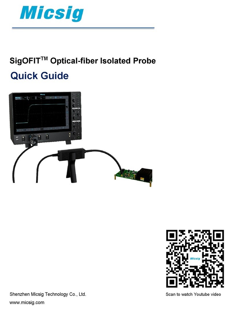
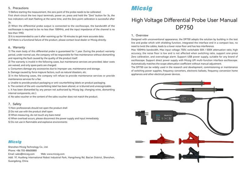
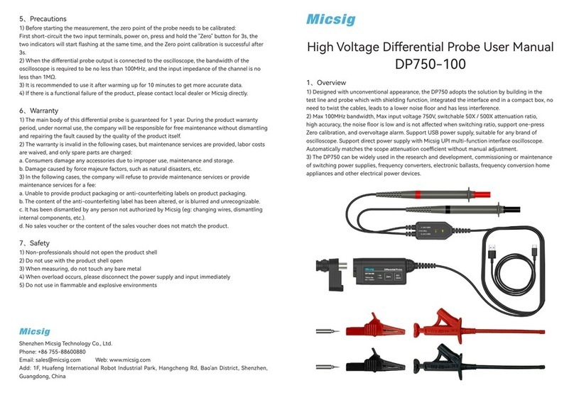
Micsig MS200 Series User manual

Handheld multifunctional oscilloscope
MS200 Serial
User Manual
Shenzhen Micsig Instruments Co., Ltd
Version information
Version
Date
comment
1.0
2013.05
2.0
2014.06

1
To customer,
Micsig MS200 serial handheld multi-functional oscilloscope includes oscilloscope,
multimeter and recorder functions, which contains the following features:
5.7 inch TFT LCD full touch screen, 640*480 resolution, 16 bit color depth
8 bit AD acquisition. Display and measurement are more precise.
Touch+Button+Scroll Wheel make handling better
Can be upgraded to 50 k wfms/s waveform refresh rate
Quick drag and zoom on touch screen, quick operating response speed
Serial bus trigger, support UART(RS232/RS422/RS485) /SPI/I2C/CAN/LIN
HDTV trigger for PAL,NTSC,SECAM,720P,1080I,1080P
31 kind of automatic measurements
Support USB Host/Slave interface, which can plug U device or connect to the PC
Detachable Li-ion battery

2
Limited warranty and limitation of liability
All Micsig products are fully inspected before delivery and guarantee all comply with test
criterion. As for warranty, please refer to product warranty card.
we authorized resellers shall extend this warranty on new and unused products to end user
only but have no authority to extend a greater or different warranty on behalf of us.
Warranty support is available if product is purchased through an authorized sales outlet or
Buyer has paid the applicable international price. We reserve the right to invoice Buyer for
importation costs to repair/replacement parts when product purchased in one country is
submitted for repair in another country.
Micsig’s warranty obligation is limited, in Micsig’s opinion, to refund of the purchase price,
free of charge repair, or replacement of a defective product, which is returned to an
authorized service center within the warranty period.

3
To obtain warranty service, contact your nearest Micsig authorized service center or sent
the product, with a description of the difficulty, postage and insurance prepaid (FOB
destination), to the nearest authorized service center. Micsig assumes no risk for damage
in transit. Following warranty repair, the product will be returned to buyer, transportation
prepaid (FOB destination). If we determine that the failure was caused by misuse,
alteration, accident or abnormal condition of operating or handling, we will provide an
estimate of repair costs and obtain authorization before commencing the work. Following
repair, the product will be returned to the buyer transportation prepaid, the buyer will be
billed for the repair, and return transportation charges (FOB Shipping Point).
This warranty is Buyer's sole and exclusive remedy and is in lieu of all other warranties,
express or implied, including but not limited to any implied warranty of merchantability or
fitness for a particular purpose. We shall not be liable for any special, indirect, incidental or
consequential damages or losses, including loss of data, whether arising from breach of
warranty or scaled on contract, tort, reliance or any other theory.
Since some countries or states do not allow limitation of the term of an implied warranty, or

4
exclusion or limitation of incidental or consequential damages, the limitations and
exclusions of this warranty may not apply to every buyer. If any provision of this warranty is
held invalid or unenforceable by a court of competent jurisdiction, such holding will not
affect the validity or enforceability of any other provision

5
Preface
Dear customers,
Hello! Firstly thanks for buying our instrument and for your proper use of this instrument,
please read this manual before using it and particularly pay attention to "safety formation".
If you have finished readout this manual, we recommend you keep this manual for future
reference.

1
CONTENT
CONTENT ................................................................................................................................................................ 1
CHAPTER ONE SAFETY INFORMATION .................................................................................................................. 1
1.1SAFETY INFORMATION......................................................................................................................................... 2
1.2 SAFETY NOTES AND SYMBOLS .............................................................................................................................. 3
CHAPTER TWO OSCILLOSCOPE QUICK START GUIDE ............................................................................................ 6
2.1GENERAL CHECK................................................................................................................................................. 8
2.2 INTRODUCE THE NAMES OF INSTRUMENT’S PARTS ................................................................................................... 9
2.3 USE BRACKET.................................................................................................................................................. 12
2.4 INSTALL AND REPLACE BATTERY .......................................................................................................................... 13
2.5 KNOW THE BUTTONS AND THEIR FUNCTIONS ........................................................................................................ 17
2.6 TURN ON &TURN OFF...................................................................................................................................... 22
2.7 TURN ON OSCILLOSCOPE................................................................................................................................... 22
2.8 GENERAL KNOWLEDGE OF USERS'INTERFACE........................................................................................................ 23
2.9 UNDERSTAND TOUCH SCREEN ............................................................................................................................ 28

2
2.10 FUNCTION TEST ............................................................................................................................................ 31
2.11 PROBE COMPENSATION .................................................................................................................................. 33
CHAPTER THREE USE OSCILLOSCOPE................................................................................................................... 39
3.1 CHANNEL SELECTION........................................................................................................................................ 42
3.2 SET CHANNEL COUPLING MODE.......................................................................................................................... 43
3.3 SET CHANNEL SAMPLING MODE.......................................................................................................................... 46
3.4 BANDWIDTH SELECTION.................................................................................................................................... 50
3.5 USE DELAY ..................................................................................................................................................... 51
3.6 SET CHANNEL POLARITY.................................................................................................................................... 53
3.7 SET CHANNEL ATTENUATION RATIO ..................................................................................................................... 55
3.8 AUTO-CALIBRATION ......................................................................................................................................... 57
3.9 SET AUTO MEASUREMENT TYPE.......................................................................................................................... 57
3.10 STORE/RESTORE MENU.................................................................................................................................. 64
3.10.1 Save................................................................................................................................................... 64
3.10.2 Restore .............................................................................................................................................. 66
3.10.3 Memory depth.................................................................................................................................. 68
3.10.4 Dynamic record................................................................................................................................. 68
3.10.5 Store settings .................................................................................................................................... 74
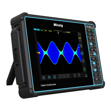
3
3.10.6 Restore settings ................................................................................................................................ 74
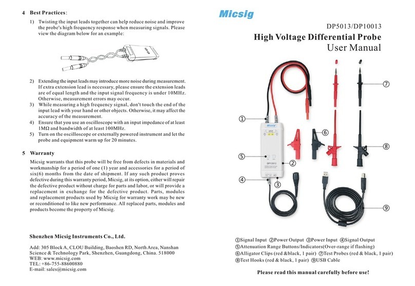
3.11 CURSOR MEASUREMENT................................................................................................................................. 75
3.12 SET DISPLAY MENU ........................................................................................................................................ 80
3.12.1 Waveform settings............................................................................................................................ 80
3.12.2 Graticule set...................................................................................................................................... 81
3.12.3 Persist adjustment............................................................................................................................ 83
3.12.4 Time base.......................................................................................................................................... 84
3.13 SET TRIGGER MENU ....................................................................................................................................... 86
3.13.1 Edge trigger ....................................................................................................................................... 89
3.13.2 Pulse width trigger ............................................................................................................................ 94
3.13.3 Logic trigger....................................................................................................................................... 97
3.13.4 Video trigger.................................................................................................................................... 102
3.13.5 Serial bus trigger.............................................................................................................................. 106
Refer to Chapter Four Serial Bus Trigger and Decode. ............................................................................... 106
3.15 USE AUTO SET............................................................................................................................................. 110
3.16 USE MATH MENU ........................................................................................................................................ 111
3.18 REFERENCE CHANNEL ................................................................................................................................... 119
3.19 USE 50% SHORTCUT.................................................................................................................................... 119

4
3.20 USE TOUCH SCREEN ZOOM WAVEFORM ........................................................................................................... 123
CHAPTER FOUR SERIAL BUS TRIGGER ............................................................................................................... 126
4.1 UART(RS232/RS422/RS485)BUS TRIGGER.............................................................................................. 129
4.2 LIN BUS TRIGGER .......................................................................................................................................... 137
4.3 CAN BUS TRIGGER ........................................................................................................................................ 142
4.4 SPI BUS TRIGGER........................................................................................................................................... 148
4.5 I2C BUS TRIGGER .......................................................................................................................................... 153
CHAPTER FIVE APPLICATION EXAMPLES ........................................................................................................... 159
5.1TAKING SIMPLE MEASUREMENT ........................................................................................................................ 161
5.2 CAPTURE SINGLE PULSE SIGNAL........................................................................................................................ 166
5.3 ANALYZE THE SIGNAL DETAIL............................................................................................................................ 169
5.4 USE MATH FFT ............................................................................................................................................. 173
CHAPTER SIX USE MULTIMETER ........................................................................................................................ 177
6.1 MULTIMETER SAFETY INFORMATION ................................................................................................................. 179
6.2 START MULTIMETER ....................................................................................................................................... 180
6.3 MULTIMETER BUTTONS AND THEIR FUNCTIONS................................................................................................... 180

5
6.4 USE MULTIMETER ......................................................................................................................................... 185
CHAPTER SEVEN USE RECORDER ....................................................................................................................... 188
7.1 START RECORDER........................................................................................................................................... 190
7.2 RECORD....................................................................................................................................................... 190
7.2.1 Multimeter record............................................................................................................................. 191
7.2.2 Oscilloscope measurement record.................................................................................................... 198
7.2.3 Oscilloscope waveform record .......................................................................................................... 202
7.2.4 Store mode set .................................................................................................................................. 206
7.3 PLAYBACK .................................................................................................................................................... 208
7.3.1 Multimeter record playback.............................................................................................................. 208
7.3.2 Oscilloscope measurement record replay ......................................................................................... 212
Follow these steps to replay oscilloscope waveform recorded. ................................................................ 215
7.3.4 The last record playback.................................................................................................................... 217
CHAPTER EIGHT USERS’ SECTION ...................................................................................................................... 218
CHAPTER NINE SCOPESUITE SOFTWARE ........................................................................................................... 232
CHAPTER TEN TROUBLESHOOTING ................................................................................................................... 234

6
CHAPTER ELEVEN SERVICES AND SUPPORT ...................................................................................................... 238
APPENDIX ........................................................................................................................................................... 242
APPENDIX A:TECHNICAL SPECIFICATIONS.............................................................................................................. 243
APPENDIX B:MAINTENANCE OF OSCILLOSCOPE...................................................................................................... 255
APPENDIX C:FACTORY DEFAULT........................................................................................................................... 257
APPENDIX D:ATTACHMENT................................................................................................................................ 266
INDEX.................................................................................................................................................................. 268

Chapter One Safety Information
Read First

1.1Safety information
To avoid personal injury and prevent from damaging products or other related devices, customer should
read safety information and use this product in accordance with the relevant provisions.
As isolated channel not supported, keep both channels connected to same GND.
Please make sure the float peak voltage is lower than 42V and effective value is lower than 36V
when doing floating measurement.
Please do not connect USD device when doing floating measurement
Only trained personnel can operate maintenance procedure
Avoid fire and personal injury
Properly connect instrument probes
View all terminal ratings. In order to avoid fire and excessive current impact, please refer all the ratings
and marks of the product specifications
Do not operate the instrument with the cover removed or the case opened.
Replace the battery in the specified method, choose the specified power adapter and recommended

3
Oscilloscope quick start guide
battery for charging.
Charge the battery properly. Please use the specified power adapter and recommended charging
period, assure adapter connected to the outlet before connected to instrument.
Avoid body contact with the exposed circuit directly
Store under the floating air
Do not use in damp or wet environment
Do not use in flammable and explosive environment
Keep the instrument’s surface dry and clean
1.2 Safety notes and symbols
Safety notes in this manual. Below safety notes and symbols will be seen throughout this manual.
Warning denotes a hazard. It calls attention to all conditions and actions may result in injury or loss of
life..

4
Oscilloscope quick start guide
Caution denotes a hazard. It calls attention to all conditions and actions may result in damage or
destruction of the instrument.
Safety notes on product
Danger means while you are in violation of the provisions of this tag may immediately cause damage to you
Warning means while you are in violation of the provisions of this tag may not immediately cause damage to
you.
Caution means cause damage to the product or others.
Symbols on products
Hazardous voltage Refer to the manual Protective earth terminal Chassis ground
Test ground
Please read the following safety information to avoid personal injury and prevent
products or damage related products. In order to avoid the possibility of danger, this
product can be used in the specified manner only.

5
Oscilloscope quick start guide
Warning
To avoid electrical shock or fire if input is more than 42Vpp (30 V rms) or connected to
the circuit of more than 4800VA
Please use the pens and voltage probes provided by the instrument, or use the standard products in the
accessory description
Before using, inspect voltage probes, test pens and accessories from mechanical which may be damaged,
please choose new proper accessories
Remove all probes, test leads and accessories if you do not want to use them.

6
Oscilloscope quick start guide
Chapter Two Oscilloscope Quick Start Guide

7
Oscilloscope quick start guide
This chapter will guide you how to operate oscilloscope, it contains the following contents
General check
Introduce the names of the instrument’s parts
Use bracket
Install& replace battery
Introduce buttons and their functions
Turn on /off
Turn on oscilloscope
Basic knowledge of oscilloscope user interface
Understand touch screen
Function test
Probe compensation

8
General check
2.1General check
When you receive your product, please check the instrument according to the following
instruction.
1. Check if damage caused by transportation
Please keep the packaging until the whole instrument and accessories pass through
electronic performance and mechanical test.
2. Check the accessories
Each oscilloscope has a packing list. You can refer it to check if the attachment is
complete. If the attachment is missing or damaged, please contact Micsig’s agent or
local office.
3. Check the instruments
If situation happens like, broken of appearance of the oscilloscope, or failure to pass
the performance taste, please contact Micsig’s agent or local office which is
responsible for this business. If the instrument damaged by transportation, please
Table of contents
Other Micsig Test Equipment manuals

Micsig
Micsig DP750-100 User manual

Micsig
Micsig MS300 Series User manual

Micsig
Micsig tbook mini Series User manual

Micsig
Micsig DP5013 User manual

Micsig
Micsig Smart Series User manual

Micsig
Micsig CP2100A User manual

Micsig
Micsig DP750 User manual

Micsig
Micsig MDP Series User manual

Micsig
Micsig SATO1000 Series User manual

Micsig
Micsig SigOFIT MOIP01P SigOFIT MOIP01P User manual
Popular Test Equipment manuals by other brands

b2 electronic
b2 electronic BA60 user manual

Novatek
Novatek CBS Series Operation and maintenance

Gossen MetraWatt
Gossen MetraWatt METRAHIT IM E-DRIVE FUSO operating instructions

Apera Instruments
Apera Instruments Salt20 instruction manual

Tektronix
Tektronix TDS3012B manual

Hach
Hach Pocket Pro+ Multi 1 user manual