Digital Lumens RLE-D1 User manual

1
RLE
IMPORTANT SAFEGUARDS – RLE
When using electrical equipment, basic safety precautions should always be followed, including the following:
READ THESE INSTRUCTIONS BEFORE USING THIS PRODUCT.
SAVE THESE INSTRUCTIONS.
Product Safety
!This product must be installed in accordance with the applicable
installation codes by a person familiar with the construction and
operation of the product and the hazards involved.
To avoid risk of electrical shock, disconnect power before installing,
wiring, or servicing the fixture.
The light source contained in this luminaire shall only be replaced by
the manufacturer or his service agent or similarly qualified person.
!
Do not apply paint, lubricants or other coatings to fixture,
suspension cables, or fasteners.
!
If you attach a safety cable, attach it to the fixture in accordance
with all national, state, and local construction codes.
!
Do not use fixture if the housing, aircraft cables, optics, or power
cable are damaged.
!
Do not touch optical lenses with your fingers or hands. In the event
you need to clean the lens, use a damp cloth and gently swab the
affected area.
!
Only handle fixture by sheet metal surfaces. Do not grasp or handle
by the fixture lenses or light bars.
!
Suitable for indoor use only.

2
RLE
1 2 3
4a 4b
4e 4f
DC:
SN:
Item:
XXX-XX-XX-XX
YYWWFFFBBBB
PPHHHHHH
PPHHHHHH-XXX-XX-XX-XX-SUF-##
SUF
##
OPT
Luminariode L ED ·Hecho en China ·Para uso interior
Madein China
120-277 VAC, 50/60 Hz, 1.26 A M aximum
120-277 V~,5 0/60 Hz, 1.26 A Máxi mo
220-240 V~,5 0/60 Hz, 151 W
Ta:65°C IP66
LBL-000308-00-A
ContainsFCC ID: Q OQMGM111
Theenclose d device complies w ith Part 15 of the FCC Ru les.
Operationis su bject to the follo wing two conditio ns: (i.) this device
maynot cause ha rmful interfere nce and (ii.) this de vice must accept
anyinterfere nce received, in cluding interfer ence that may caus e
undesiredoperation.
RLE-D1-ST
警告:電源電圧は感電の危険あり
開封禁止- 製品内部に手を触れないでください
高湿度の場所に設置可能
室温65°C未満の場所で最適に動作
輸入業者:株式会社UKCエレクトロニクス
Avertissement : Tension secteur – ri sque d'électroc ution
Aucunepièc e interne réparabl e par l'utilisateur – Ne pa s ouvrir
Convientaux locaux humides
Fonctionnementadaptéa ux températuresne dépassant pas 65 °C
Warnung:Gefahreines Stromschlags bei Netzspannung
Wartungnur du rch autorisierte s Fachpersonal — Nic ht öffnen
FürFeuchträume geeignet
Fürden Betrieb b ei Temperaturen bis 65°C geeignet
Advertencia: Riesgo de desca rga eléctric a con el votaje en línea
Nocontiene pa rts que requira n servicio del us uarioI — No se abra
Apropiadoparasitios húmedos
Apropiadopa ra operacion en te mperaturas que n o excedan 65°C
Warning:Line vol tage risk of shock
Nouser-servic eable parts — D o not open
Suitablefordamp locations
Suitablefor o peration in temp eratures not excee ding 65°C
65°C
DC:
SN:
Item:
XXX-XX-XX-X-XXX
YYWWFFF BBBB
PPHHHHHH
XXXXXXXX-XXX-XX-XX-X-XXX-XX
SUF
##
OPT
ControllerSerial Label
PPHHHHHH-SCN-GA-00-X-##
Item:
XXX-XX-XX-X-XXX
YYWW FFF BBBB
PPHHHHHH
XXXXXXXX-XXX-XX-XX-X-XXX-XX
SUF
##
OPT
OPT [PlaceController
LabelHere]
ControllerSerial Label
PPHHHHHH-SCN-GA-00-X-##
DC:
SN:
Item:
XXX-XX-XX-X-XXX
YYWWFFF BBBB
PPHHHHHH
XXXXXXXX-XXX-XX-XX-X-XXX-XX
SUF
##
OPT [PlaceController
LabelHere]
ControllerSerial Label
PPHHHHHH-SCN-GA-00-X-##
DC:
SN:
Item:
XXX-XX-XX-X-XXX
YYWWFFF BBBB
PPHHHHHH
XXXXXXXX-XXX-XX-XX-X-XXX-XX
SUF
##
OPT [PlaceController
LabelHere]
ControllerSerial Label
PPHHHHHH-SCN-GA-00-X-##
DC:
SN:
Item:
XXX-XX-XX-X-XXX
YYWWFFF BBBB
PPHHHHHH
XXXXXXXX-XXX-XX-XX-X-XXX-XX
SUF
##
OPT [PlaceController
LabelHere]
ControllerSerial Label
PPHHHHHH-SCN-GA-00-X-##
DC:
SN:
Item:
XXX-XX-XX-X-XXX
YYWWFFF BBBB
PPHHHHHH
XXXXXXXX-XXX-XX-XX-X-XXX-XX
SUF
##
OPT [PlaceController
LabelHere]
ControllerSerial Label
PPHHHHHH-SCN-GA-00-X-##
DC:
SN:
Item:
XXX-XX-XX-X-XXX
YYWWFFF BBBB
PPHHHHHH
XXXXXXXX-XXX-XX-XX-X-XXX-XX
SUF
##
OPT [PlaceController
LabelHere]
ControllerSerial Label
PPHHHHHH-SCN-GA-00-X-##
DC:
SN:
Item:
XXX-XX-XX-X-XXX
YYWWFFF BBBB
PPHHHHHH
XXXXXXXX-XXX-XX-XX-X-XXX-XX
SUF
##
OPT [PlaceController
LabelHere]
ControllerSerial Label
PPHHHHHH-SCN-GA-00-X-##
DC:
SN:
Item:
XXX-XX-XX-X-XXX
YYWWFFF BBBB
PPHHHHHH
XXXXXXXX-XXX-XX-XX-X-XXX-XX
SUF
##
OPT [PlaceController
LabelHere]
ControllerSerial Label
PPHHHHHH-SCN-GA-00-X-##
DC:
SN:
Item:
XXX-XX-XX-X-XXX
YYWWFFF BBBB
PPHHHHHH
XXXXXXXX-XXX-XX-XX-X-XXX-XX
SUF
##
OPT [PlaceController
LabelHere]
ControllerSerial Label
PPHHHHHH-SCN-GA-00-X-##
DC:
SN:
Item:
XXX-XX-XX-X-XXX
YYWWFFF BBBB
PPHHHHHH
XXXXXXXX-XXX-XX-XX-X-XXX-XX
SUF
##
OPT [PlaceController
LabelHere]
ControllerSerial Label
PPHHHHHH-SCN-GA-00-X-##
DC:
SN:
Item:
XXX-XX-XX-X-XXX
YYWWFFF BBBB
PPHHHHHH
XXXXXXXX-XXX-XX-XX-X-XXX-XX
SUF
##
OPT [PlaceController
LabelHere]
ControllerSerial Label
PPHHHHHH-SCN-GA-00-X-##
DC:
SN:
Item:
XXX-XX-XX-X-XXX
YYWWFFF BBBB
PPHHHHHH
XXXXXXXX-XXX-XX-XX-X-XXX-XX
SUF
##
OPT [PlaceController
LabelHere]
ControllerSerial Label
PPHHHHHH-SCN-GA-00-X-##
DC:
SN:
Item:
XXX-XX-XX-X-XXX
YYWWFFF BBBB
PPHHHHHH
XXXXXXXX-XXX-XX-XX-X-XXX-XX
SUF
##
OPT [PlaceController
LabelHere]
ControllerSerial Label
PPHHHHHH-SCN-GA-00-X-##
DC:
SN:
Item:
XXX-XX-XX-X-XXX
YYWWFFF BBBB
PPHHHHHH
XXXXXXXX-XXX-XX-XX-X-XXX-XX
SUF
##
OPT [PlaceController
LabelHere]
ControllerSerial Label
PPHHHHHH-SCN-GA-00-X-##
DC:
SN:
Item:
XXX-XX-XX-X-XXX
YYWWFFF BBBB
PPHHHHHH
XXXXXXXX-XXX-XX-XX-X-XXX-XX
SUF
##
OPT [PlaceController
LabelHere]
ControllerSerial Label
PPHHHHHH-SCN-GA-00-X-##
DC:
SN:
Item:
XXX-XX-XX-X-XXX
YYWWFFF BBBB
PPHHHHHH
XXXXXXXX-XXX-XX-XX-X-XXX-XX
SUF
##
OPT [PlaceController
LabelHere]
ControllerSerial Label
PPHHHHHH-SCN-GA-00-X-##
DC:
SN:
Item:
XXX-XX-XX-X-XXX
YYWWFFF BBBB
PPHHHHHH
XXXXXXXX-XXX-XX-XX-X-XXX-XX
SUF
##
OPT [PlaceController
LabelHere]
ControllerSerial Label
PPHHHHHH-SCN-GA-00-X-##
DC:
SN:
Item:
XXX-XX-XX-X-XXX
YYWWFFF BBBB
PPHHHHHH
XXXXXXXX-XXX-XX-XX-X-XXX-XX
SUF
##
OPT [PlaceController
Label Here]
ControllerSerial Label
PPHHHHHH-SCN-GA-00-X-##
DC:
SN:
Item:
XXX-XX-XX-XX
YYWWFFF BBBB
PPHHHHHH
PPHHHHHH-XXX-XX-XX-XX-SUF-##
SUF
##
OPT
OPT [Place Controller
Label Here]
ControllerSerial Label
PPHHHHHH-SCN-GA-00-X-##
DC:
SN:
Item:
XXX-XX-XX-X X
YYWW FFF BBBB
PPHHHHHH
PPHHHHHH-XXX-XX-XX-XX-SUF-##
SUF
##
OPT
Arrows indicate aisle direction.
!
INSTALLATION INSTRUCTIONS: Illustrations – RLE
4c
4d
Arrows indicate aisle direction.
!
3
RLE
INSTALLATION INSTRUCTIONS: Illustrations – RLE, cont.
5a
5b
NL
4g 4h

4
RLE
!Product Ratings
RLE-D1-ST: 120-277 V AC, 50/60 Hz, 145 W (max), 1.21 A (max)
RLE-H1-ST: 120-277 V AC, 50/60 Hz, 214 W (max), 1.79 A (max)
RLE-P1-ST: 120-277 V AC, 50/60 Hz, 428 W (max), 3.56 A (max)
RLE-D1-HV: 347-480 V AC, 50/60 Hz, 148 W (max), 0.43 A (max)
RLE-H1-HV: 347-480 V AC, 50/60 Hz, 217 W (max), 0.63 A (max)
RLE-P1-HV: 347-480 V AC, 50/60 Hz, 434 W (max), 1.25 A (max)
INSTALLATION INSTRUCTIONS
1: Verify Optic Type
Use optic type specified in the project plan — WIDE or NARROW.
Hint: The optic type is printed on the fixture label (Illustration 1).
2: Add Tracking Labels to Sticker Book
Detach plastic bag from fixture, then remove product and controller
barcode label assembly from bag and affix to sticker book, as depicting
the intended installation location of the fixture (Illustration 2).
3: Rotate Light Bars
a. Rotate the lightbars into position as specified in the project plan
(Illustration 3).
Note: Ensure at the light bar release buttons are secured within
the appropriate detents.
Note: Refer to Appendix B for typical lightbar positioning examples.
4: Install Fixtures
Note: Fixture must be positioned at least 0.2m (8 in) from the ceiling.
Note: Fastening hardware supplied by installer.
Option 2a: Aircraft Cable – RLE-D1/H1
a. Refer to the sticker book to confirm the correct location and
placement of the fixture.
b. Secure aircraft cable to a beam or truss.
c. Connect cable to fixture housing using aircraft cable hanging
hardware (Illustration 4e).
d. Use a box level to level the fixture.
Hint: For aisle illumination, verify that fixture is oriented correctly
(Illustration 4f).
Option 2b: Aircraft Cable – RLE-P1
a. Refer to the sticker book to confirm the correct location and
placement of the fixture.
b. Secure aircraft cable to a beam or truss.
c. Connect cable to fixture housing using aircraft cable hanging
hardware (Illustration 4g).
d. Use a box level to level the fixture.
Hint: For aisle illumination, verify that fixture is oriented correctly
Illustration 4h).
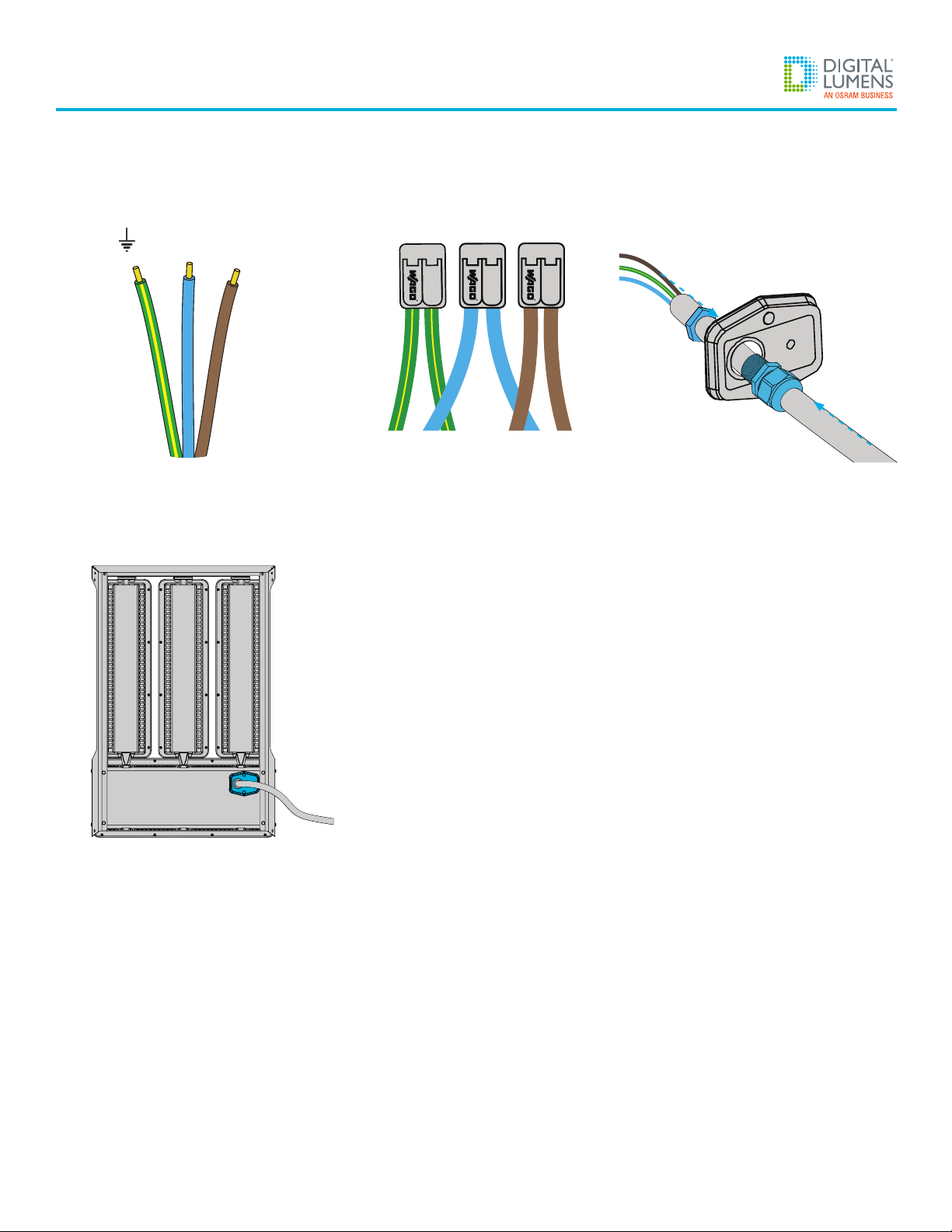
5: Make Electrical Connections
Suitable for cords 1.5mm2–2.5mm2
Do not connect or disconnect while under load.
e. Remove (2x) Phillips®screws retaining the wiring compartment
access panel (Illustration 5a).
f. Extract the internal three-wire bundle from wiring compartment
(Illustration 5b) and identify the wire leads (Illustration 5c).
g. Connect external wiring to internal wire bundle using supplied
WAGO splicing connectors (Illustration 5d).
h. Use supplied cable gland or suitable IP-rated wiring connector
(supplied by installer) to route power cable through access panel
(Illustration 5e).
i. Replace wiring compartment access panel and tighten screws to
8 kgf-cm (Illustration 5f).
6: Verify Sticker Book
To prevent issues during commissioning, ensure that the placement
of the bar code label in the sticker book corresponds to the fixture’s
physical location in the facility.
GETTING STARTED
5
RLE
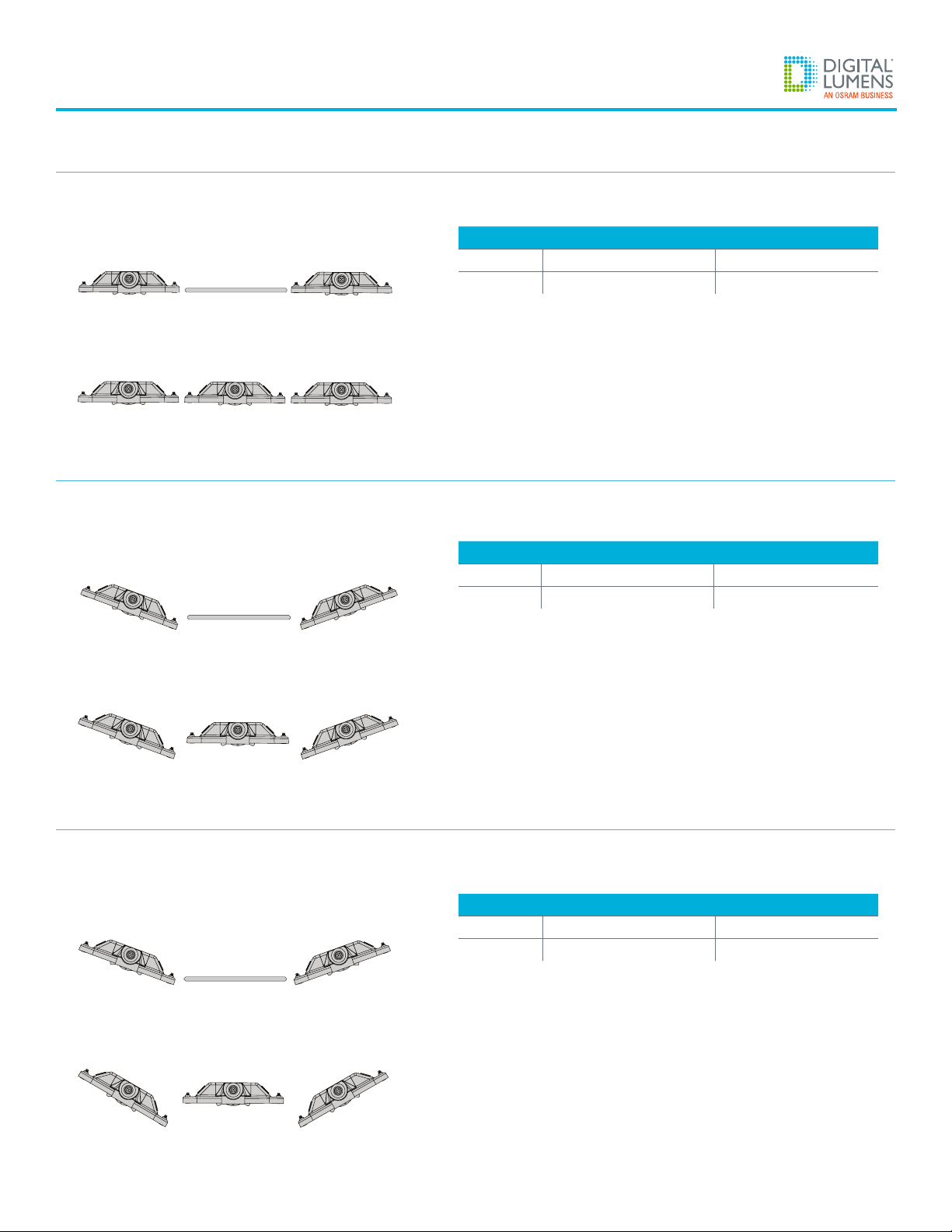
Open Area Application (manufacturing, storage, loading dock)
Fixture Optic Light Bar Setting
RLE-D1 WIDE 0°, 0°, 0°, 0°
RLE-H1/P1 WIDE 0°, 0°, 0°, 0°
Highbay / Racked Application
Fixture Optic Light Bar Setting
RLE-D1 NARROW -10°, 10°
RLE-H1/P1 NARROW -20°, 0°, 20°
Highbay / Racked Application (widely-spaced fixtures)
Fixture Optic Light Bar Setting
RLE-D1 NARROW -20°, 20°
RLE-H1/P1 NARROW -30°, 0°, 30°
0° 0° 0°
RLE-D1
RLE-H1/P1
0° 0° 0°
Example 1
RLE-D1
RLE-H1/P1
-10° 10°
-20° 0° 20°
0°
Example 2
-20° 20°
-30° 0° 30°
RLE-D1
RLE-H1/P1
0°
Example 3
Appendix B: Lightbar Examples
6
RLE
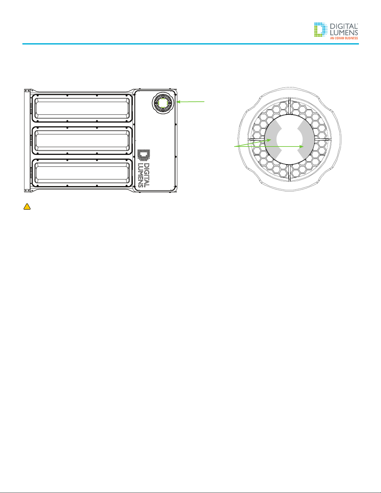
Appendix C: Installing a Sensor Mask
1. Determine Sensor Mask Orientation
The sensor mask decals must align with the short edge of the fixture.
2. Apply Sensor Mask to Optic
One at a time, remove the adhesive backing. Carefully, place each mask decals along either side of the sensor optic, as shown above.
Do not cover any other part of the optic.
!
For fixtures with Narrow optics only
Sensor
Optic
Sensor Mask
Decals
Masked Sensor Optic

7
RLE
Appendix D: Control Module Field Replacement
1. Remove Existing Control Module
a. Disconnect power from the fixture.
b. Use the tabs on the control module to rotate it 1/8-turn counter-clockwise, and then extract the module from the fixture housing.
2. Install Replacement Control Module
a. Insert the replacement module and rotate it 1/8-turn clockwise while lightly pushing down, until there is an audible ‘click’.
b. Restore power to the fixture.
Note: To ensure network connectivity following module replacement, update the facility map file using Digital Lumens commissioning software.
Control
Module
Tabs

www.digitallumens.com
374 Congress Street, Suite 600
Boston, MA USA 02210
+1 (617) 723-1200
All Rights Reserved © 2010-2019
Digital Lumens Incorporated
Subject to change without noce.
DOC-001706-00 Rev A 09-19
Importador mexicano:
Energetika Sustentable y Ecológica, S.A. de C.V.
Avenida Patriotismo 12 Int 2 201
Hipódromo, Cuauhtémoc, C.P 06100
Tel. +52 (55) 6237-9342
H2O Arquitectos Asociados, S.A. de C.V.
Fresnillo 107 Col. AÍameda, Celaya, Guanajuato
Mexico, C.P 38050
Tel. +52 (55) 5350-3957
This manual suits for next models
3
Table of contents
Other Digital Lumens Lighting Equipment manuals


Popular Lighting Equipment manuals by other brands

NICOR
NICOR ECL5 Series installation instructions

Knightsbridge
Knightsbridge EMRNST Installation & maintenance manual

Prestige
Prestige Venus Q7M user manual

Experia
Experia IRiS instruction manual

Commercial Electric
Commercial Electric SPKM-7W02 Use and care guide

Artistic License
Artistic License Data-Lynx O/P user guide


