NICOR ECL5 Series User manual
NICOR, Inc. 2200 Midtown Place NE, Albuquerque, NM 87107 P: 800.821.6283 F: 800.892.8393 www.nicorlighting.com December 10, 2019 11:30 AM
ECL5 LED Combo Exit Sign & Emergency Light
INSTALLATION INSTRUCTIONS
Model: ECL51UNVWHR2, ECL51UNVWHG2
What’s In The Box
One (1) ECL5 One (1) Mounting Kit
WARNING
- Risk of re or electric shock. LED installation requires knowledge of luminaires electrical systems. Review the diagrams thoroughly
before beginning. All electrical connections must be in accordance with local codes, ordinances, and the National Electric Code. If
not qualied, do not attempt installation. Contact a qualied licensed electrician.
- Before installation, disconnect the power by turning o the circuit breaker or by removing the appropriate fuse at the fuse box.
Using the light switch to turn power o is not sucient to prevent electrical shock.
- May be used outdoors under cover. (-15°C - 40°C)
- Do not let power supply cords touch hot surfaces.
- Do not mount near gas or electric heaters.
- Use caution when servicing batteries, all servicing should be completed by qualied personnel. Replace every 8 to 10 years
according to ambient. Test regularly in accordance with local codes.
- To prevent wiring damage or abrasion, do not expose wiring to edges of sheet metal or other sharp objects.
- Do not use this equipment for other than its intended use.
- The use of accessory equipment not recommended by the manufacturer may cause an unsafe condition.
- Equipment should be mounted in locations and at heights where it will not be subjected to tampering by unauthorized personnel.
- Only use UL Listed, Suitable for Wet Location conduit parts. Use exible conduit ONLY.
- Allow batteries to charge for 24 hours before rst use.
Tools Needed
A Phillips screwdriver and a drill will be needed to install
the ECL5.
Make sure all power is turned o before beginning installation
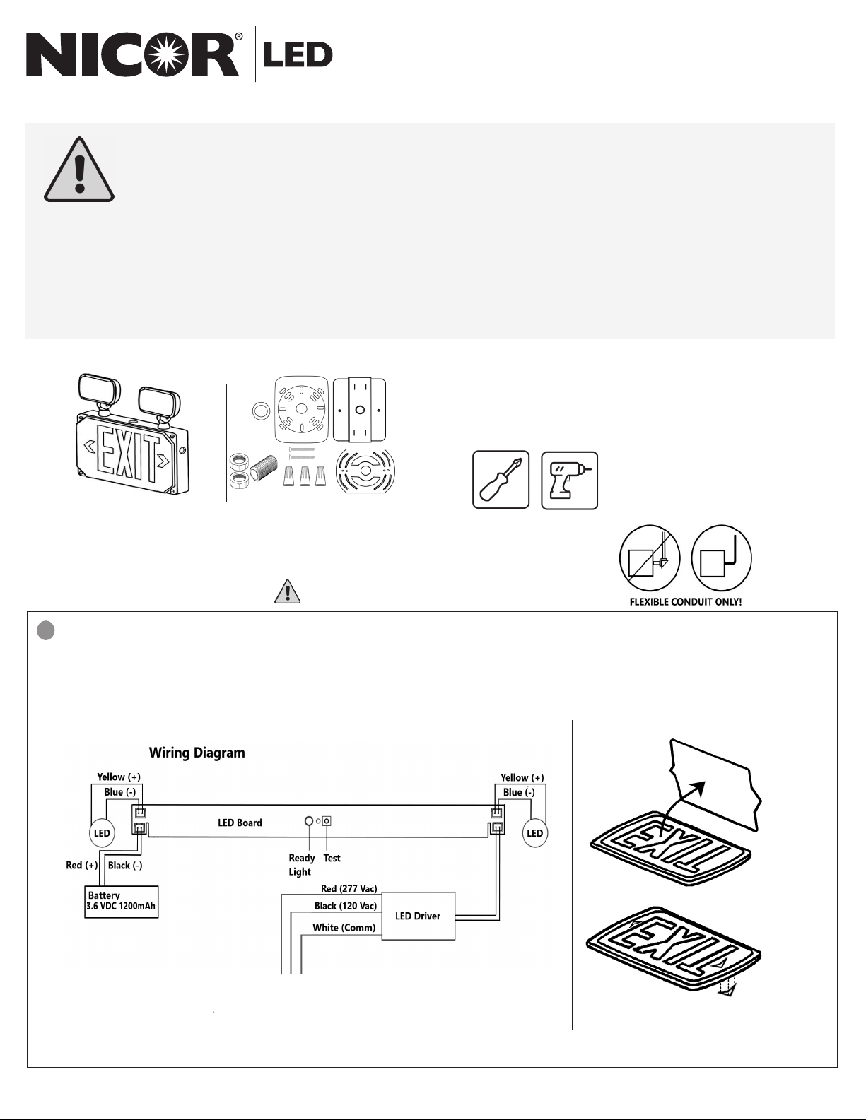
Preparation
Carefully unpack the exit light from its packaging. Inspect product for defects due to shipping. Become familiar
with the wiring diagram below before beginning installation. Take the faceplate o of the xture, remove the plastic
diuser. Remove the appropriate chevron arrow knockout, gently using your ngers or a small tool, then replace the
plastic diuser. If using double face option, remove the appropriate chevron arrow of the second faceplate. Set the
faceplate(s) and screws aside.
1
Installing the ECL5
Figure 1 - Wiring Diagram
Figure 2 - Chevron Arrow
Removal
NICOR, Inc. 2200 Midtown Place NE, Albuquerque, NM 87107 P: 800.821.6283 F: 800.892.8393 www.nicorlighting.com December 10, 2019 11:30 AM
ECL5 LED Combo Exit Sign & Emergency Light
INSTALLATION INSTRUCTIONS
Model: ECL51UNVWHR2, ECL51UNVWHG2
2.1
2
2.1
Mounting Instructions
Surface Wall Mounting
• If back mounting, skip to section 2.2.
• Remove appropriate knockout by drilling a 3/4” hole.
• Thread nut onto pipe nipple. Slide pipe nipple through
canopy center hole.
• Remove backing from self adhesive junction box gasket
and adhere to back of mounting canopy. Remove back-
ing from self adhesive pipe thread gasket and adhere to
front of mounting canopy.
• Place the screws provided in the holes on the canopy.
• Feed the power supply through knockout, pipe, and metal mounting plate, as seen in “Figure 3 - Wall Mount.”Direct
input wires along walls of the xture to protect the wires and prevent shadowing.
• Ensure that power is o, then connect the power supply, 120 or 277 VAC, to the appropriate input wires, using the
provided wire nuts, according to the wiring diagram in Figure 1. The unused wire must be capped o using the
extra wire nut.
• Push wire connections into the junction box. Mount metal bracket to junction box (j-box and hardware not includ-
ed).
• Secure the canopy to the steel mounting plate. Place pipe nipple through the mounting hole of the housing to
lock the canopy into place. Once canopy is locked into position there will not be any side-to-side movement of the
canopy.
• Connect batteries to LED board using snap in connectors. Secure the faceplate(s) to the xture: snap in the white
faceplate, then screw on clear cover. Do not over tighten screws.
NOTE: Figure 3 shown as single face install, for double face: install additional EXIT faceplate.
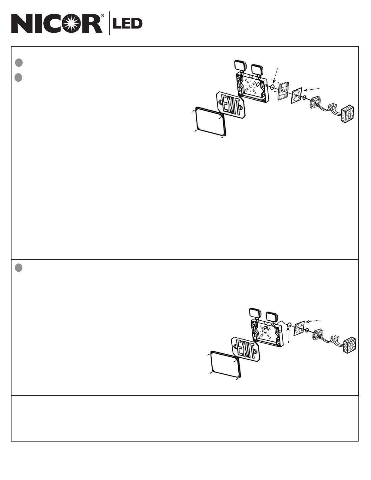
2.2 Back Mounting
• Drill or knock out appropriate knockouts on the backplate to t junction box mounting points and the center knock-
out for the input wire leads.
• Remove backing from self adhesive junction box gasket and adhere to back plate.
• Feed the power supply through the knockout. Direct the input wires along the walls of the xture to protect the wires
and prevent shadowing. Run the wires through the mounting
bracket as seen in Figure 4.
• Ensure that power is o, then connect the power supply, 120
or 277 Vac, to the appropriate input wires, using the provided
wire nuts, according to the wiring diagram in Figure 1.
• Mount the metal bracket to the J-box (hardware not included).
• Using the provided (2) mounting screws, secure the xture to
the mounting bracket.
• Connect the battery to the LED board. Secure the faceplate
to the xture: snap in the white faceplate, then screw on clear
cover. Do not over tighten the screws.
Figure 3 - Wall Mount
Figure 4 - Back Mount
NOTE
Battery Testing: Allow 24 hours of charging before testing.
• Push In TEST Button - LED display will switch to battery power and remain lit
• Release TEST Button - LED display will switch back to AC power
Large
Gasket
Small
Gasket
Small
Gasket
Large
Gasket

NICOR, Inc. 2200 Midtown Place NE, Albuquerque, NM 87107 P: 800.821.6283 F: 800.892.8393 www.nicorlighting.com December 10, 2019 11:30 AM
ECL5 LED Combo Exit Sign & Emergency Light
INSTALLATION INSTRUCTIONS
Model: ECL51UNVWHR2, ECL51UNVWHG2
LED EXPRESS LIMITED WARRANTY
Subject to the exclusions below, each NICOR LED product, including the LED electronics and components of a property installed NICOR LED product, will be free from defect in materials and workmanship for a period of ve
(5) years from the original date of purchase. The product shall be considered defective only if 10% or more of the product’s LED components fail. NICOR LED product warranty covers the following performance criteria: LED
Light Output will be maintained above 70% of initial output; LED color temperature will not shift more than 200K in CCT; LED driver will operate within NICOR specications; and the xture nish, excluding natural aluminum
or brass products, will not exhibit cracking, peeling, excessive fading, or corrosion during the warranty period. Exceptions apply as dened in NICOR’s product specication sheets, which are incorporated by reference herein.
This limited warranty is provided to you, the purchaser of the product identied on Seller’s invoice, as your exclusive remedy and applies only to NICOR products that have been purchased from an authorized NICOR
Distributor; the product was new and in an unopened NICOR package at the time of installation; and the NICOR product was installed by a licensed electrician or under the supervision of a licensed electrician and used by
consumers in the United States or Canada when accompanied with this warranty. This warranty extends only to the rst consumer purchaser and is not transferable. A consumer wishing to invoke the terms of this limited
warranty must rst obtain a RGA number within 30 days of discovery of the defect, and return the product to NICOR for inspection. Once veried to be covered by this limited warranty, NICOR will, at its sole discretion, repair,
replace, or refund the purchase price of any product that does not conform to this limited warranty. If NICOR, at its sole discretion, determines that the product should be repaired or replaced, this warranty is limited to the
reasonable, customary, and necessary costs and expenses associated with the repair/replacement. This warranty requires that all repair/replacement estimates and costs, including but not limited to equipment rental (if any),
and any other cost or expense to be incurred in the repair/replacement of the product, be approved in advance and in writing by NICOR.
FAILURE TO OBTAIN NICOR’S ADVANCE WRITTEN APPROVAL OF ALL REPAIR/REPLACEMENT COSTS AND EXPENSES IN WRITING SHALL VOID THIS LIMITED WARRANTY.
THIS LIMITED WARRANTY DOES NOT COVER THE FOLLOWING:
• Defects or damages resulting from improper installation, operation, storage, misuse or abuse, accident, or neglect;
• Defects or damages resulting from improper service, testing, adjustment, installation, maintenance, alteration, connection to out-of-specication electrical service, corrosive or damp environments, or connection to incom-
patible equipment or devices (e.g., connecting non-dimmable lighting products to dimmers);
• Damage which occurs in transit;
• Power surges or overheating due to external conditions
• Acts of nature including but not limited to lightning strikes
ANY IMPLIED WARRANTIES, INCLUDING WITHOUT LIMITATION, THE IMPLIED WARRANTIES OF MERCHANTABILITY AND FITNESS FOR A PARTICULAR PURPOSE SHALL BE LIMITED TO THE DURATION OF THIS LIMITED WARRANTY,
OTHERWISE THE REPAIR, REPLACEMENT, OR REFUND AS PROVIDED UNDER THIS EXPRESS LIMITED WARRANTY IS THE EXCLUSIVE REMEDY OF THE CONSUMER, AND IS PROVIDED IN LIEU OF ALL OTHER WARRANTIES, EXPRESS
OR IMPLIED. IN NO EVENT SHALL NICOR BE LIABLE, WHETHER IN CONTRACT OR IN TORT (INCLUDING NEGLIGENCE) FOR DAMAGES IN EXCESS OF THE PURCHASE PRICE OF THE PRODUCT, OR FOR ANY INDIRECT, INCIDENTAL,
SPECIAL OR CONSEQUENTIAL DAMAGES OF ANY KIND, OR LOSS OF REVENUE OR PROFITS, LOSS OF BUSINESS OR OTHER FINANCIAL LOSS ARISING OUT OF OR IN CONNECTION WITH THE ABILITY OR INABILITY TO USE THE
PRODUCT TO THE FULL EXTENT THESE DAMAGES MAY BE DISCLAIMED BY LAW.
This device complies with part 15 of the FCC Rules. Operation is subject to the following two conditions: (1) This device may not cause harmful interference, and (2) this device must accept any interference received, includ-
ing interference that may cause undesired operation.
NOTE: This equipment has been tested and found to comply with the limits for a Class B digital device, pursuant to part 15 of the FCC Rules. These limits are designed to provide reasonable protection against harmful
interference in a residential installation. This equipment generates, uses and can radiate radio frequency energy and, if not installed and used in accordance with the instructions, may cause harmful interference to radio
communications. However, there is no guarantee that interference will not occur in a particular installation. If this equipment does cause harmful interference to radio or television reception, which can be determined by
turning the equipment o and on, the user is encouraged to try to correct the interference by one or more of the following measures:
—Reorient or relocate the receiving antenna.
—Increase the separation between the equipment and receiver.
—Connect the equipment into an outlet on a circuit dierent from that to which the receiver is connected.
—Consult the dealer or an experienced radio/TV technician for help
SCAN the QR or visit
www.nicorlighting.com/support/survey
SHARE YOUR EXPERIENCE WITH US
FOLLOW US
This manual suits for next models
2
Table of contents
Other NICOR Lighting Equipment manuals

NICOR
NICOR LED ECL3 User manual

NICOR
NICOR TPE Series User manual

NICOR
NICOR EML7 User manual

NICOR
NICOR EXL6 User manual

NICOR
NICOR LED EMB4001UNV Series User manual

NICOR
NICOR EML6 User manual

NICOR
NICOR EMB250 -10-UNV User manual

NICOR
NICOR NLCSPCW1WH User manual

NICOR
NICOR ECL21UNVWHR2 User manual

NICOR
NICOR EXL2 Series User manual


