manuals.online logo
Brands
  1. Home
  2. •
  3. Brands
  4. •
  5. Digital Watchdog
  6. •
  7. Camera Accessories
  8. •
  9. Digital Watchdog DWC-GPLT-W User manual

Digital Watchdog DWC-GPLT-W User manual

Other Digital Watchdog Camera Accessories manuals

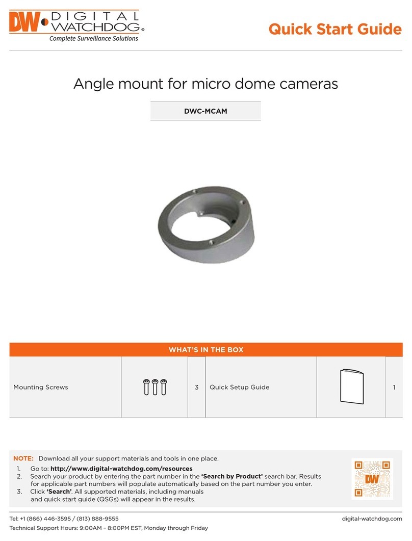
Digital Watchdog DWC-MCAM User manual

Digital Watchdog

Digital Watchdog DWC-MCAM User manual

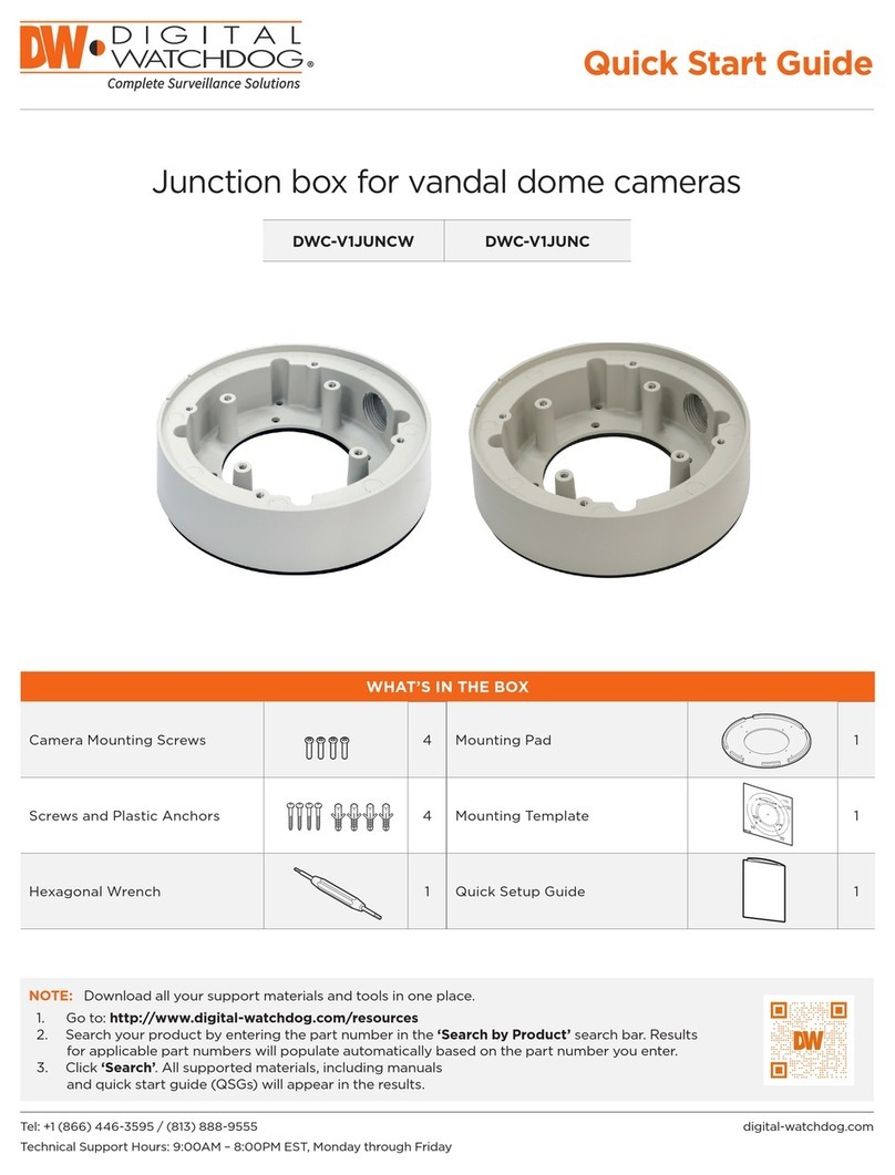
Digital Watchdog DWC-V1JUNCW User manual

Digital Watchdog

Digital Watchdog DWC-V1JUNCW User manual

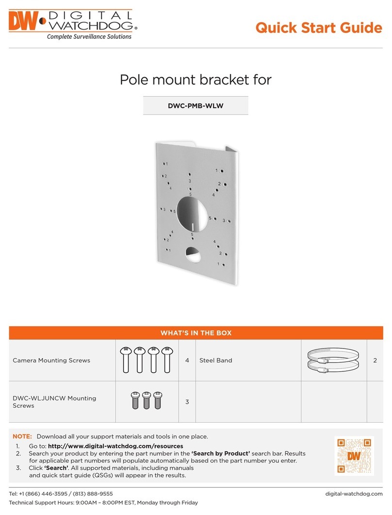
Digital Watchdog DWC-PMB-WLW User manual

Digital Watchdog

Digital Watchdog DWC-PMB-WLW User manual

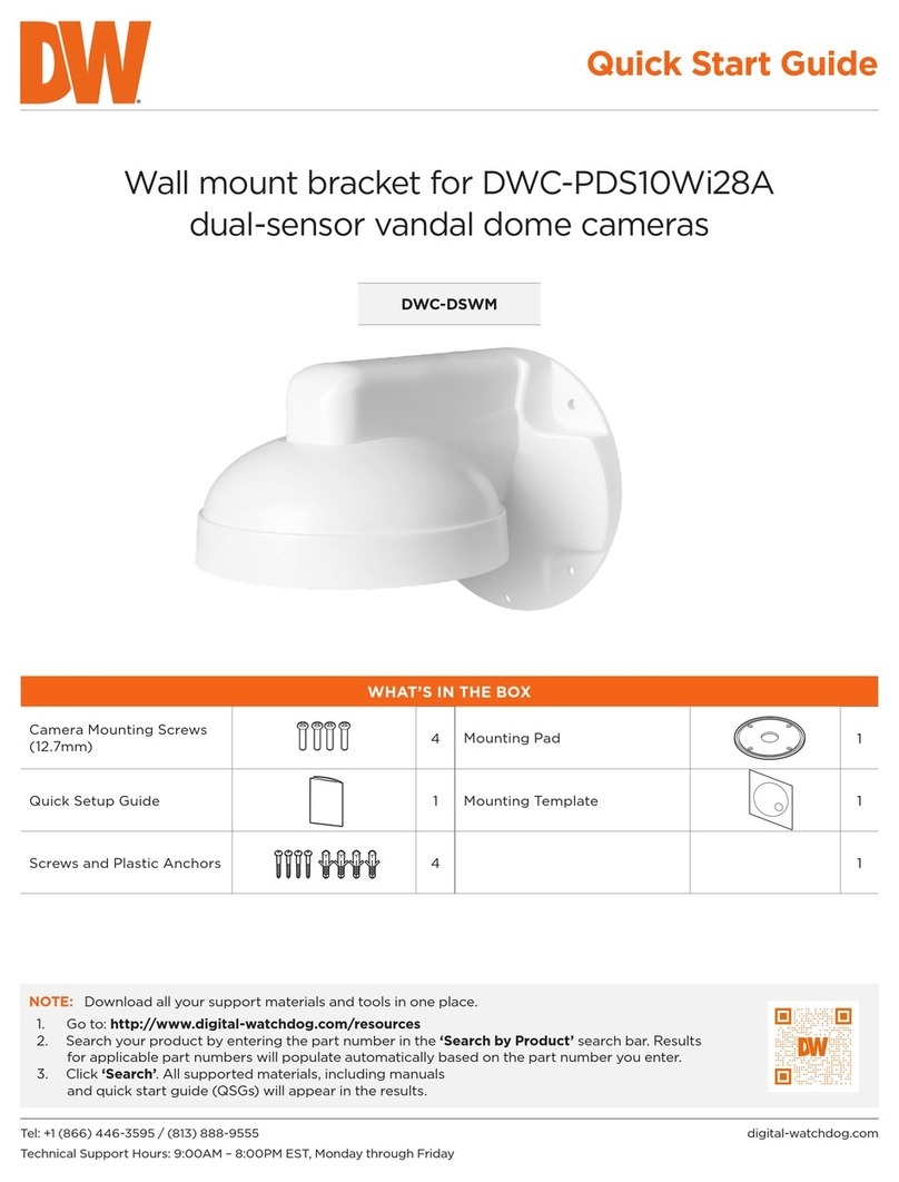
Digital Watchdog DWC-DSWM User manual

Digital Watchdog

Digital Watchdog DWC-DSWM User manual

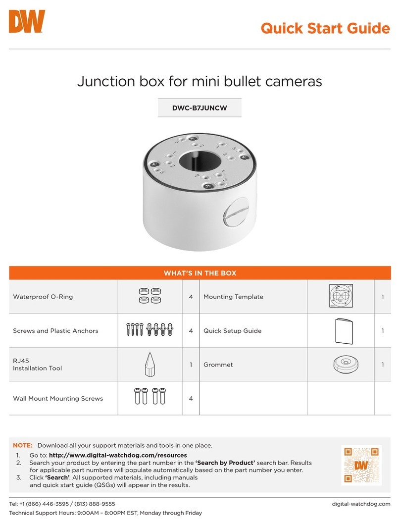
Digital Watchdog DWC-B7JUNCW User manual

Digital Watchdog

Digital Watchdog DWC-B7JUNCW User manual

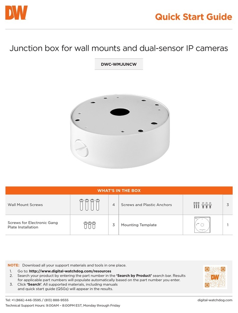
Digital Watchdog DWC-WMJUNCW User manual

Digital Watchdog

Digital Watchdog DWC-WMJUNCW User manual

Digital Watchdog DWC-EXTIR100 User manual

Digital Watchdog

Digital Watchdog DWC-EXTIR100 User manual

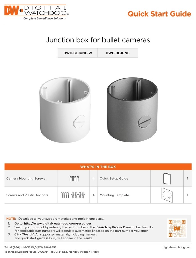
Digital Watchdog DWC-BLJUNC-W User manual

Digital Watchdog

Digital Watchdog DWC-BLJUNC-W User manual

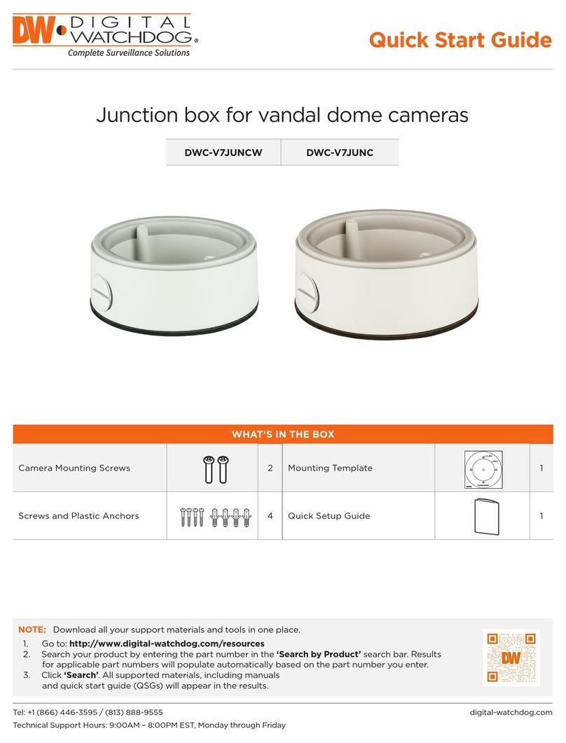
Digital Watchdog DWC-V7JUNCW User manual

Digital Watchdog

Digital Watchdog DWC-V7JUNCW User manual

Digital Watchdog DWC-C223W User manual

Digital Watchdog

Digital Watchdog DWC-C223W User manual

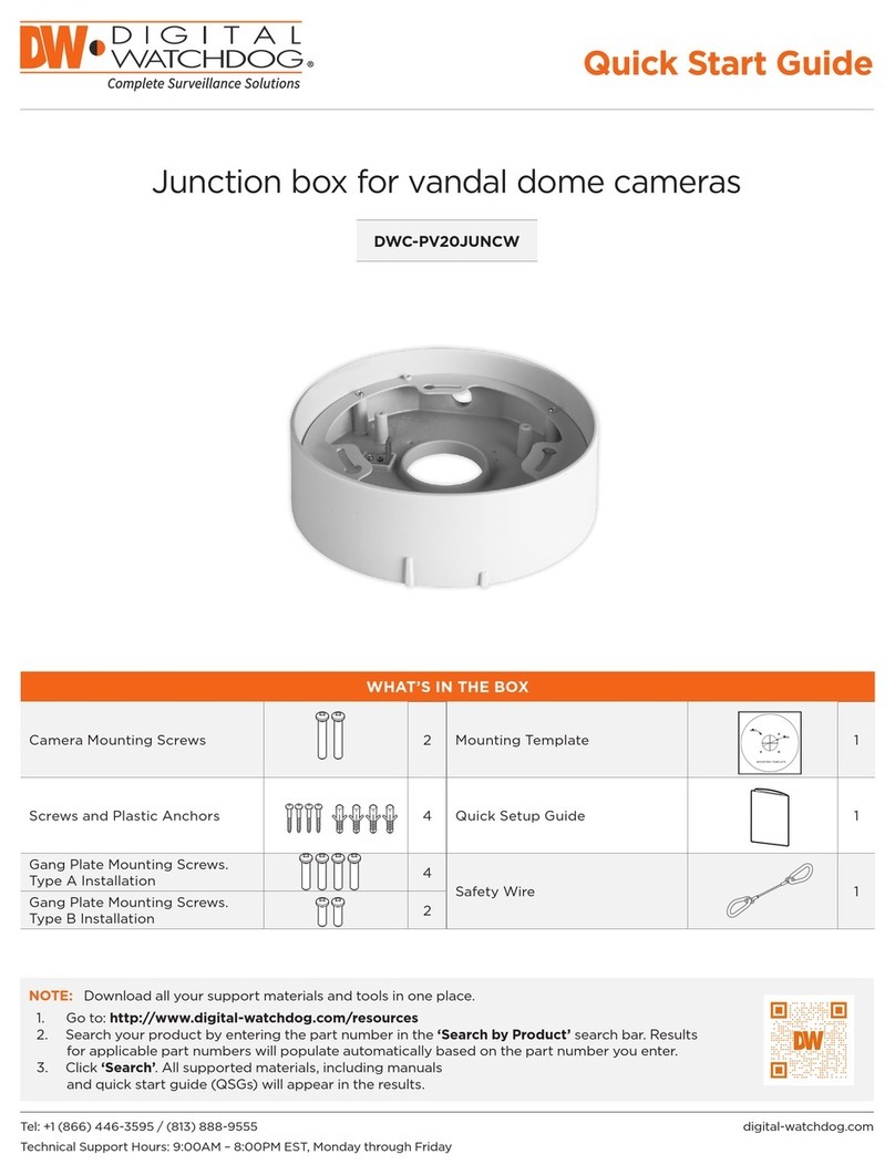
Digital Watchdog DWC-PV20JUNCW User manual

Digital Watchdog

Digital Watchdog DWC-PV20JUNCW User manual

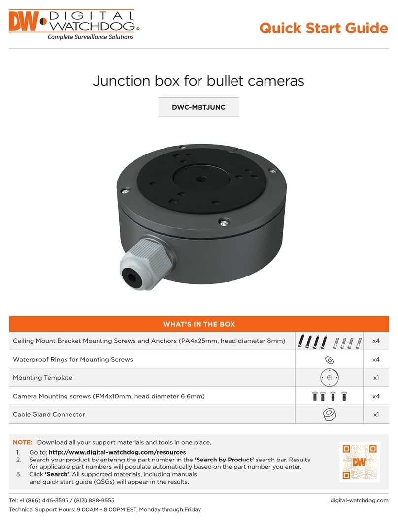
Digital Watchdog DWC-MBTJUNC User manual

Digital Watchdog

Digital Watchdog DWC-MBTJUNC User manual

Popular Camera Accessories manuals by other brands

CamRanger CamRanger user manual

CamRanger

CamRanger CamRanger user manual

Custom Brackets HDV CAGE KIT Instructions for use

Custom Brackets

Custom Brackets HDV CAGE KIT Instructions for use

Aegis ABL052010P user manual

Aegis

Aegis ABL052010P user manual

Saft SRA Series Installation and operating instructions

Saft

Saft SRA Series Installation and operating instructions

Kodak TIB5200 technical information

Kodak

Kodak TIB5200 technical information

Videotec HEG instruction manual

Videotec

Videotec HEG instruction manual

Ikelite 6171.11 manual

Ikelite

Ikelite 6171.11 manual

Pentax Auto Bellows Slide Copier K user manual

Pentax

Pentax Auto Bellows Slide Copier K user manual

Nikon UT-1 user manual

Nikon

Nikon UT-1 user manual

dji RONIN 4D quick start guide

dji

dji RONIN 4D quick start guide

SLIK ABLE 300DX user manual

SLIK

SLIK ABLE 300DX user manual

Rebelcell 36V70 user manual

Rebelcell

Rebelcell 36V70 user manual

Trojan GC2 48V quick start guide

Trojan

Trojan GC2 48V quick start guide

Calumet 7100 Series CK7114 operating instructions

Calumet

Calumet 7100 Series CK7114 operating instructions

Ropox 4Single Series User manual and installation instructions

Ropox

Ropox 4Single Series User manual and installation instructions

Cambo Wide DS Digital Series Main operating instructions

Cambo

Cambo Wide DS Digital Series Main operating instructions

Samsung SHG-120 Specification sheet

Samsung

Samsung SHG-120 Specification sheet

Ryobi BPL-1820 Owner's operating manual

Ryobi

Ryobi BPL-1820 Owner's operating manual

manuals.online logo
manuals.online logoBrands
  • About & Mission
  • Contact us
  • Privacy Policy
  • Terms and Conditions

Copyright 2025 Manuals.Online. All Rights Reserved.

DWC-GPLT-W
Converter plate for electronic gang box
Quick Start Guide
Tel: +1 (866) 446-3595 / (813) 888-9555
Technical Support Hours: 9:00AM – 8:00PM EST, Monday through Friday
digital-watchdog.com
NOTE: Download all your support materials and tools in one place.
1. Go to: http://www.digital-watchdog.com/resources
2. Search your product by entering the part number in the ‘Search by Product’ search bar. Results
for applicable part numbers will populate automatically based on the part number you enter.
3. Click ‘Search’. All supported materials, including manuals
and quick start guide (QSGs) will appear in the results.
WHAT’S IN THE BOX
Option A Installation Screws 4
Camera Mounting Screws 3
sets
Option B Installation Screws 2
Quick Manual
Ver. 1.0 / 2020.06
Before installing and using the Camera, please read this manual carefully.
Be sure to keep it handy for future reference.
Dome Camera
Gang Plate Manual
1. Dimension & Accessories
Mounting Gang Plate to Gang Box (Optional)
Mount Point 1 Installation
Mount Point 2 Installation
Mount Point 2# Installation
Mount Point 4 Installation
Mount Point 3 Installation
Mount Point 6Installation
B : 2-Gang Handy Boxes / Switch Boxes
A : Handy Boxes
Mount Point 5 Installation
2. Installation
A Install ScrewPlate Mount Screw
NK4
VD5
NK6
VD8
VF2
VD11
VD13
VD14
VF9
VD9
VD1VD2
VD7NK2
B Install Screw
MOUNT POINT 1
NK4 / NK6 / VD5
MOUNT POINT 2
VD8 / VD9 / VD11 / VD15 / VF2 / VF9
MOUNT POINT 2#
VD13
MOUNT POINT 3
VD14
MOUNT POINT 4
VD1 / VD2 / VD7 / NK2
MOUNT POINT 5
VP2/ VP3
MOUNT POINT 6
NK5
VP2
NK5
VP3
M3.0x 20mm
with Rubber
Gasket
M3.0x 35mm
M3.0x 23mm
1. Connect the converter plate to an electric gang box.
Use the 4 screws (A) included with the converter plate when using a 2-gang handy electrical box or switch box.
Use the 2 screws (B) included with the converter plate when using a 1-gang handy electrical box.
2. Pass wires through and make the connections.
Use the CABLE-OUT spaces in the converter plate.
3. Follow the table below to connect the camera to the appropriate mounting points and which screws set to use.
Mounting
holes Compatible cameras Screw size
Mounting
point 1
DWC-V4 models 20mm screws
DWC-MV4 models 20mm screw
DWC-V6 models 20mm screw
Mounting
point 2, 2#
DWC-MF and DWC-MPF models 20mm screw
DWC-MV8 and DWC-MPV8 models 23mm screw
DWC-MVC and DWC-MPVC models 20mm screw
DWC-MVD and DWC-MPVD models 35mm screws
DWC-PVF and DWC-PPVF models 20mm screw
Mounting
point 4
DWC-MV7 and DWC-MPV7 models 20mm screw
DWC-V7 models 20mm screw
DWC-MVA and DWC-MPVA models 20mm screw
DWC-VA models 20mm screw
DWC-D4 models 20mm screw
DWC-MF and DWC-MPF models OLD HARDWARE 20mm screw + rubber gasket
DWC-MV8 and DWC-MPV8 models OLD HARDWARE 20mm screw + rubber gasket
DWC-PVF and DWC-PPVF models OLD HARDWARE 20mm screw + rubber gasket
Mounting
point 5
DWC-D3 models 20mm screw
DWC-MD7 models 20mm screw
Mounting
point 6 DWC-MD4 models 20mm screw
4. Mount the camera to the upper side of the converter plate.
INSTALLATION
Quick Start Guide
Rev:06/23
Copyright © Digital Watchdog. All rights reserved.
Specifications and pricing are subject to change without notice.
* NOTE: How to tell what MF, V8 or PVF hardware you have:
If the camera’s mounting holes are located on the outer edge of the camera’s base,
use mounting points labeled as “2, #2” WITHOUT the included rubber gaskets.
If the camera’s mounting holes are located on the inner edge of the camera’s base,
use mounting points labeled as “4” WITH the included rubber gaskets.
steel boxes, covers and accessories
RACO bOxes, COveRs And ACCessORies
A70
detailed drawings
HAndy bOxes And switCH bOxes
2-GANG HANDY BOXES / SWITCH BOXES
cAt. # dimEnSionS
A (inSidE)
b c
400 1-1/2" --
420 2" --
501 2-1/2" --
502 2-1/2" 1-31/32" 4"
503 2-1/2" --
505 2-1/2" 7" 2-13/64"
506 2-1/2" --
508 2-1/2" --
509 2-1/2" --
560 2-3/4" --
561 2-3/4" --
562 2-3/4" 7" 2-13/64"
565 2-3/4" --
591 3-1/2" --
592 3-1/2" --
500, 8500 2-1/2" --
504, 8504 2-1/2" 7" 2-13/64"
590, 8590 3-1/2" --
SINGLE GANG AND GANGABLE CONDUIT SWITCH BOXES
HANDY BOXES
cAt. # dimEnSionS
A (inSidE)
b c
661 1-7/8" 6-7/16" 2-7/32"
662 1-7/8" 7" 2-3/8"
655 1-1/2" 1-31/32" 4-1/8"
670rAc 2-1/8" --
8670 2-1/8" --
674 2-1/8" --
678 2-1/8" 7" 2-3/8"
650, 8650 1-1/2" --
650cSA 1-1/2" --
653 1-1/2" --
660, 8660 1-7/8" --
611 1-7/8" --
660Sm1-7/8" --
663, 8663 1-7/8" --
663Sm1-7/8" --
665 1-7/8" --
671 2-1 /8" 6 -7/16" 2-7/32"
cAt. # dimEnSionS
A (inSidE)
b c d E
680 2-1/8" 4" 4" --
681 2-1/8" 4" 4" 7" 4-9/32"
683 2-1/8" 4" 4" --
685 2-1/8" 4" 4" 7" 4-9/32"
steel boxes, covers and accessories
RACO bOxes, COveRs And ACCessORies
A70
detailed drawings
HAndy bOxes And switCH bOxes
2-GANG HANDY BOXES / SWITCH BOXES
cAt. # dimEnSionS
A (inSidE)
b c
400 1-1/2" --
420 2" --
501 2-1 /2" --
502 2-1/ 2" 1-31/32" 4"
503 2-1/ 2" --
505 2-1/ 2" 7" 2-13/64"
506 2-1/2" --
508 2-1/ 2" --
509 2-1/ 2" --
560 2-3/4" --
561 2-3/4" --
562 2-3/4" 7" 2-13/64"
565 2-3/4" --
591 3-1/2" --
592 3-1/2" --
500, 8500 2-1/2" --
504, 8504 2-1/2" 7" 2-13/64"
590, 8590 3-1 /2" --
SINGLE GANG AND GANGABLE CONDUIT SWITCH BOXES
HANDY BOXES
cAt. # dimEnSionS
A (inSidE)
b c
661 1-7/8" 6-7/16" 2-7/32"
662 1-7/8" 7" 2-3/8"
655 1-1/2" 1-31/32" 4-1/8"
670rAc 2-1/8" --
8670 2-1 /8" --
674 2-1/8" --
678 2-1/8" 7" 2-3/8"
650, 8650 1-1/2" --
650cSA 1-1 /2" --
653 1-1/2" --
660, 8660 1-7/8" --
611 1-7/8" --
660Sm1-7/8" --
663, 8663 1-7/8" --
663Sm1-7/8" --
665 1-7/8" --
671 2-1 /8" 6-7/16" 2-7/32"
cAt. # dimEnSionS
A (inSidE)
b c d E
680 2-1/ 8" 4" 4" --
681 2-1/8" 4" 4" 7" 4-9/32"
683 2-1/ 8" 4" 4" --
685 2-1/8" 4" 4" 7" 4-9/32"
Quick Manual
Ver. 1.0 / 2020.06
Before installing and using the Camera, please read this manual carefully.
Be sure to keep it handy for future reference.
Dome Camera
Gang Plate Manual
1. Dimension & Accessories
Mounting Gang Plate to Gang Box (Optional)
Mount Point 1 Installation
Mount Point 2 Installation
Mount Point 2# Installation
Mount Point 4 Installation
Mount Point 3 Installation
Mount Point 6Installation
B : 2-Gang Handy Boxes / Switch Boxes
A : Handy Boxes
Mount Point 5 Installation
2. Installation
A Install ScrewPlate Mount Screw
NK4
VD5
NK6
VD8
VF2
VD11
VD13
VD14
VF9
VD9
VD1VD2
VD7NK2
B Install Screw
MOUNT POINT 1
NK4 / NK6 / VD5
MOUNT POINT 2
VD8 / VD9 / VD11 / VD15 / VF2 / VF9
MOUNT POINT 2#
VD13
MOUNT POINT 3
VD14
MOUNT POINT 4
VD1 / VD2 / VD7 / NK2
MOUNT POINT 5
VP2/ VP3
MOUNT POINT 6
NK5
VP2
NK5
VP3
A. 2-gang handy electrical box
and switch boxes
A. 2-Gang handy Boxes /
switch boxes
B. 1-gang handy electrical box B. handy boxes
Quick Manual
Ver. 1.0 / 2020.06
Before installing and using the Camera, please read this manual carefully.
Be sure to keep it handy for future reference.
Dome Camera
Gang Plate Manual
1. Dimension & Accessories
Mounting Gang Plate to Gang Box (Optional)
Mount Point 1 Installation
Mount Point 2 Installation
Mount Point 2# Installation
Mount Point 4 Installation
Mount Point 3 Installation
Mount Point 6Installation
B : 2-Gang Handy Boxes / Switch Boxes
A : Handy Boxes
Mount Point 5 Installation
2. Installation
A Install ScrewPlate Mount Screw
NK4
VD5
NK6
VD8
VF2
VD11
VD13
VD14
VF9
VD9
VD1VD2
VD7NK2
B Install Screw
MOUNT POINT 1
NK4 / NK6 / VD5
MOUNT POINT 2
VD8 / VD9 / VD11 / VD15 / VF2 / VF9
MOUNT POINT 2#
VD13
MOUNT POINT 3
VD14
MOUNT POINT 4
VD1 / VD2 / VD7 / NK2
MOUNT POINT 5
VP2/ VP3
MOUNT POINT 6
NK5
VP2
NK5
VP3