digitalview VideoFlyer VF-200 User manual
VideoFlyer 20”
Model : VF-200
User Guide
Introduction
The following is intended as a guide to installation and initial setup of the standard 20”
VideoFlyer, an Internet connected digital video player and display.
This Guide covers:
•Mounting information How to attach the unit to a fixture
•Installation of a Compact Flash (CF) memory card
•Power On/off, power considerations
•Setup using the optional 8 segment touch screen
•Operation How to play video on VideoFlyer
Preparation
It is advisable to do a quick check that the display is working properly prior to installation. Simply
install the CF card as explained below and then power on. If the unit powers up then proceed with
installation.
CF Card Installation
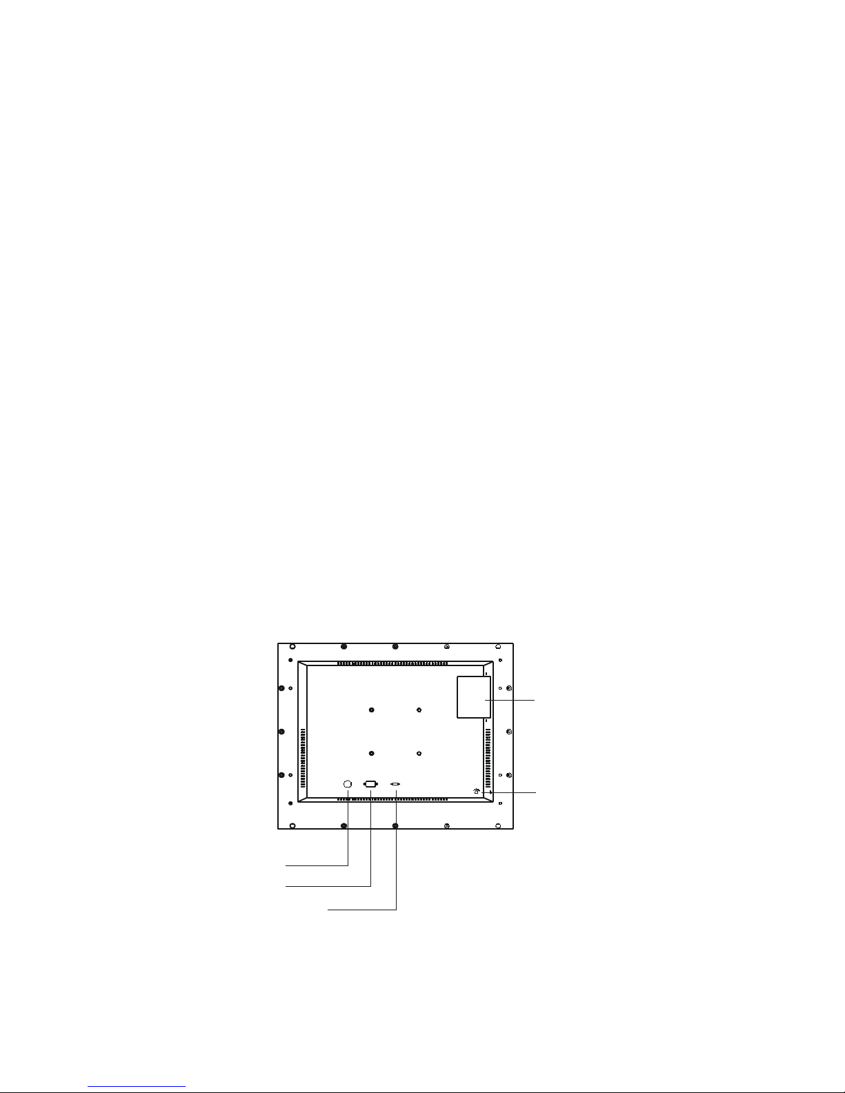
•Remove the access cover on the rear of the display unit, see diagram.
•The CF card should be inserted carefully with the label side visible. WARNING: Do not force
the CF card. Forcing the CF card can damage the connector pins in the display unit and result
in expensive repairs.
•To eject the card push the Eject button as shown in the diagram.
20” VideoFlyer User Guide July 2006 v.m4.0
Volume
DC 12V RS - 2 2
Normal Test
CF Card
compartment
Volume
Control
Power in
RS-2 2
Test / Normal switch
(Default set to No rmal)

Mounting
The housing is of metal construction and has 4 threaded mounting holes on the rear of the
housing, (see diagram below).
Points to note
Mounting It is recommended to use a mounting bracket that allows the display to be set to the
ideal viewing angle.
Sound Speakers are on the bottom of the housing, ensure they are not covered.
The diagram shows the mountin holes used on the
VideoFlyer Range. The 20" model has both holes Ref A
and B available.
Ref Standard
AVESA
BVESA
C Digital View
Use mounting holes reference A or B, ie 1 mm and
75mm spacing
Power
The display system is supplied with an AC to DC power adaptor. This should be connected to the
mains.
The power switch is mounted on the back of the housing, ensure the unit is switched on. If you
have a custom version with no power switch on the housing then the unit will power on
immediately it is connected to the power supply. If it does not then please check the power supply.
Notes
Power input 12V DC, 6A (min.)
Power cord You need an AC power cord that is certified for the country or region you are
located. Using an improper power cord might cause severe damage to your unit.
20” VideoFlyer User Guide July 2006 v.m4.0
Screws are 4mm diameter
100mm (A)
100mm (A)
75mm (B)
75mm (B)
50mm (C)
50mm (C)
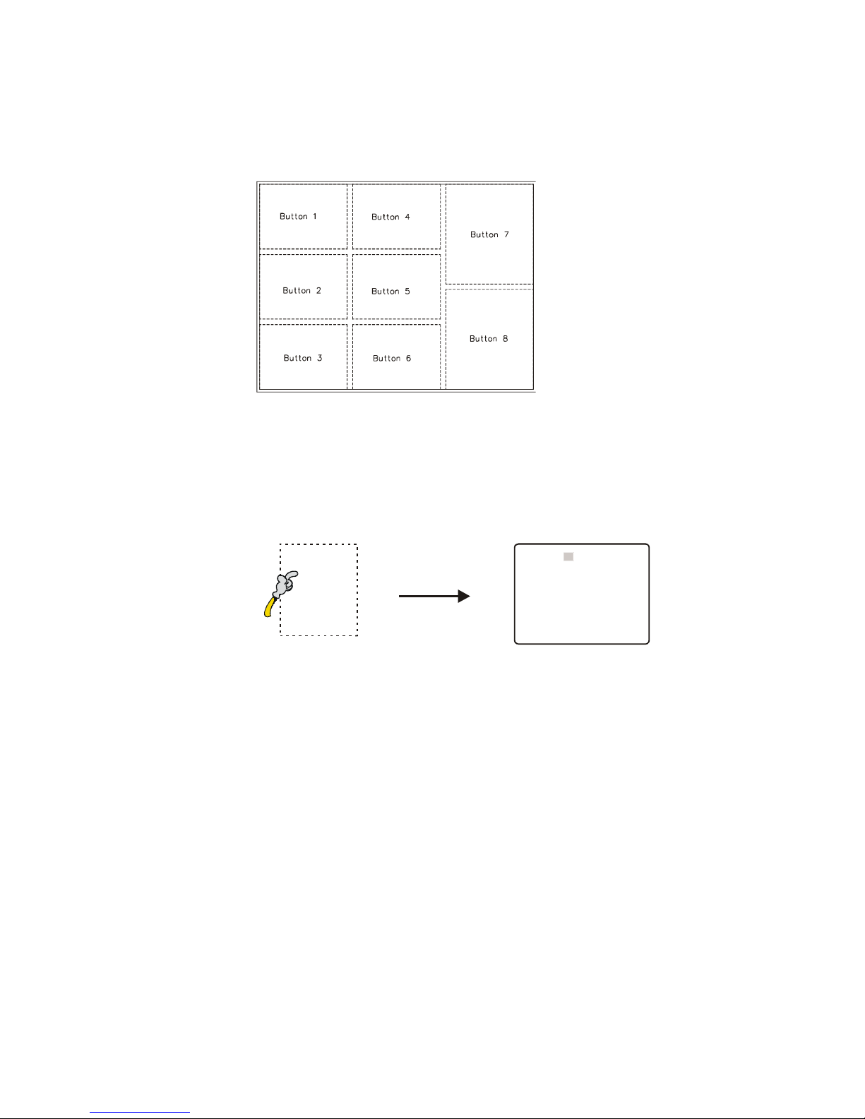
Display Setup (touc screen versions only)
1. The touch screen, if fitted, has 8 touch segments (buttons) which can be programmed with DV
Studio software to perform in VCD player mode or specific track select functions.
2. Config mode
To enter the Config. Mode, holding the button 8 and power up.
The volume setting can be adjusted when the config. mode is enabled.
Press button 8 + power up Config. mode enable.
Press button 7 Increase the volume level / Save
Press button 6 Decrease the volume level / Save
Press button 8 Select
20” VideoFlyer User Guide July 2006 v.m4.0
VOLUME 14 VER 4.10
Y M D H M S
2004 .10 .12 15 : 48 : 44
ID NO: 0712
DATA LOGGING: ON
OSD: ON
SAVE AND EXIT
Button 8
Power on
Holding the button Config. Mode menu

Operation
CAUTION Never connect or disconnect parts of the system when the system is powered up as
this may cause serious damage.
All the features described in the following points can be set by the DV Studio software. See DV
Studio User Guide for more details.
1) Autoplay, Manual Play at power startup
Insert CompactFlash Card containing the captured MPEG-1/MPEG-2 files.
Turn on the Remote Flyer.
Set power switch to ON position. The power LED lights up to confirm power is being
supplied to system.
The option of AutoPlay or manual play of tracks at powering up of unit is selected in the
DV Studio software when writing the MPEG files on to CompactFlash Card.
In Auto play mode the first track of the Playlist set in DV Studio software will
automatically play after power up.
In Manual Play mode after power up press any button and the first track of the Playlist set
in DV Studio software will play.
2) Auto-loop playing of video tracks
Tracks can be set by the DV Studio software to play in a continuous loop, individually or
in sequence one after another.
3) Simple playback
The simple playback is only applicable in all remote flyer and remote player. Customer
just copying all those MPEG files (.mpg) to the Compactflash card and make sure the
project (.prj) and playlist (.pll) files had been removed. The remote flyer will playback the
MPEG file(s) automatically in ALPHABETICAL order of its filename. For still picture
MPEG file, the play time can be defined by the last digit of the filename. (For example,
Apple5.mpg – where “5” means play the track for 5 seconds.)
20” VideoFlyer User Guide July 2006 v.m4.0

SAFETY NOTICES
WARNING : TO REDUCE THE RISK OF FIRE OR ELECTRIC SHOCK, DO NOT
EXPOSE THIS APPARATUS TO RAIN OR MOISTURE
RISK OF ELECTRIC SHOCK
DO NOT OPEN
Whilst care has been taken to provide as much detail as possible for use of this product it cannot
be relied upon as an exhaustive source of information. This product is for installation by suitably
qualified persons who understand the nature of the work they are doing and are able to take
suitable precautions and produce a result that is safe and meets regulatory requirements.
T ere are no user serviceable parts in t is product.
Do not touch HIGH VOLTAGE PART of the lamp cables while turn on. Customer will be
in danger of an electric shock.
This sign has a meaning that user will be injured by himself, if the user makes a mistake
in operations.
IMPORTANT SAFETY INSTRUCTIONS
Precautions for use, read the following instructions:
Keep these instructions.
Follow all instructions and heed all warnings.
Do not use this product near water, or environments where it can get wet.
Keep clean only with dry cloth.
Do not block any ventilation openings.
Do not install near any heat sources such as radiators, heat registers, stoves, or other
apparatus (including amplifiers) that produce heat.
Do not defeat the safety purpose of the grounding-type plug. A grounding type plug has
two blades and a third grounding prong. The third prong are provided for your safety. If
the provided plug does not fit into your outlet, consult an electrician for replacement of
the obsolete outlet.
Protect the power cord from being walked on or pinched particularly at plugs,
convenience receptacles, and the point where they exit from the apparatus.
Only use attachments/accessories specified by the manufacturer.
Unplug this apparatus during lightning storms or when unused for long periods of time.
Refer all servicing to qualified service personnel. Servicing is required when the
apparatus has been damaged in any way, such as power-supply cord or plug is
damaged, liquid has been spilled or objects have fallen into the apparatus, the
apparatus has been exposed to rain or moisture, does not operate normally, or has
been dropped.
Power Supply Replacement and Services Information: When replacement of power
supply is required, please return it to the nearest service center.
20” VideoFlyer User Guide July 2006 v.m4.0
Table of contents
Other digitalview Media Player manuals


