digitalview M3-310 User manual

M3-310 OEM Media Player
USER GUIDE
Version 1.2

Page 2 of 36
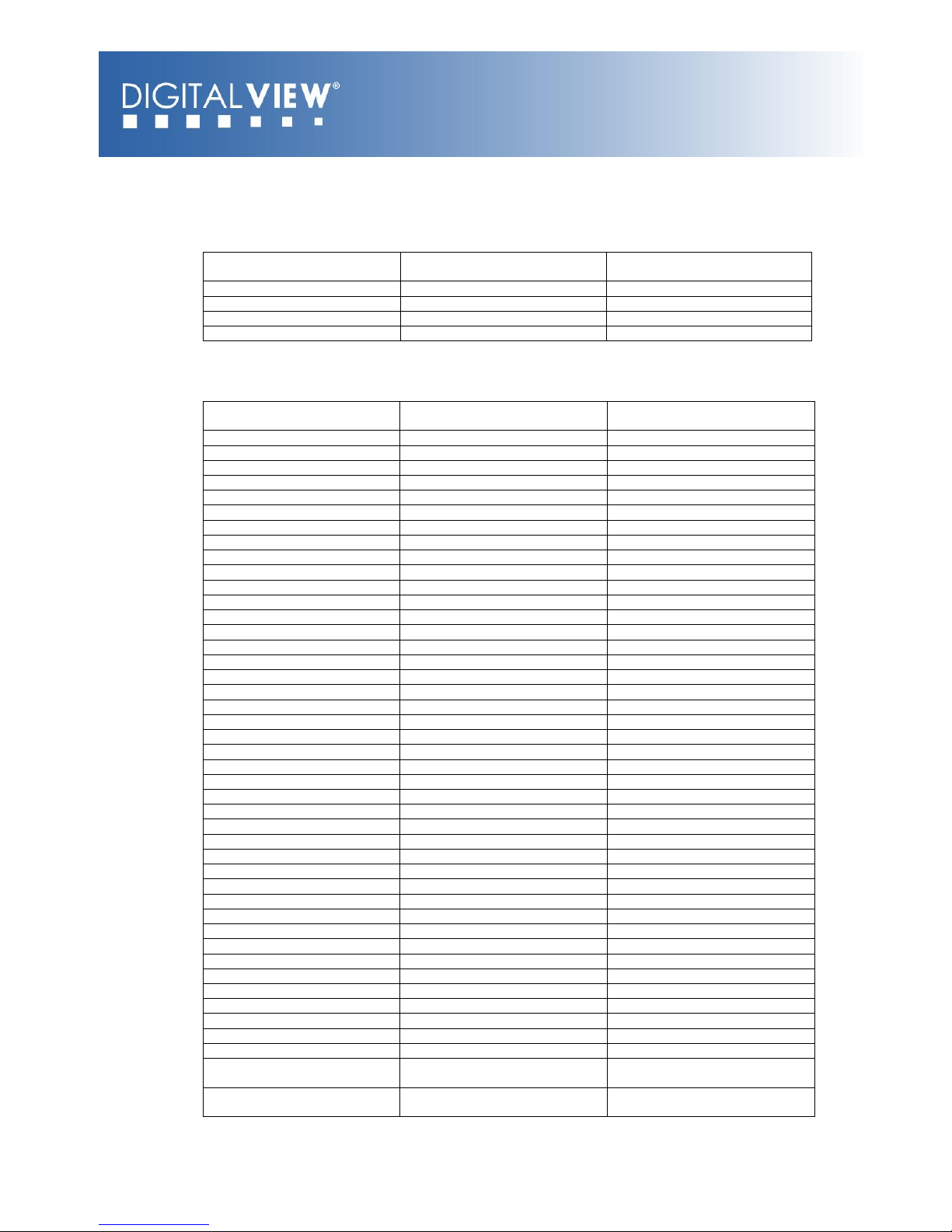
Revision History
Amendment Date
Version
March 2009
V 1.0
April 2009
V 1.1
October 2009
V 1.2

Page 3 of 36
Table of Contents
1 Introduction................................................................................ 4
2 System Design ............................................................................ 5
2.1 Familiarization...................................................................... 5
3 Connection Overview ................................................................... 7
3.1 Prepare for connection........................................................... 7
3.2 Basic connection for M3-310................................................... 7
4 System Notes ............................................................................. 9
5 Connectors, pinouts & jumpers .....................................................12
5.1 Jumpers setting...................................................................13
5.2 Pin Assignment....................................................................15
6LCD Display Setup ......................................................................21
6.1 Use of OSD switch mount......................................................21
6.2 OSD Functions for LCD display...............................................22
7Operating Setup .........................................................................24
7.1 OSD Configuration ...............................................................24
7.2 Start up .............................................................................25
7.2.1 Start track mode..........................................................25
7.2.2 Sleep mode.................................................................25
7.3 Loop Playback .....................................................................26
8Playback Operation .....................................................................27
8.1 Playback modes...................................................................27
8.1.1 Playlist mode...............................................................27
8.1.2 Simple play mode ........................................................27
8.2 Operating functions..............................................................28
8.3 Formatting Compact flash card ..............................................29
8.4 Exporting Project and Playlist ................................................30
8.5 USB update.........................................................................32
9Dimension .................................................................................33
10 Specification ............................................................................34

Page 4 of 36
1Introduction
The M3-310 is an embedded video media player OEM board with a built in LCD
interface. The board is ideally suited for fanless solid-state media player and
LCD display products for market applications such as digital signage, retail
promotion systems and information displays in places such as museums.
This brief guide explains how to set up the M3-310 media player board. It is
intended for system integrators looking to build a media player with an
integrated LCD display.
A few of the key features:
Suitable for fanless system designs with CF card storage
Supports a wide range of LCD panels
Media support includes:
oMPEG-1, MPEG-2, MPEG-4 (DIvX)
oMPEG still
oJPEG
Dedicated button interface
External communication and control through RS-232 (full protocol set
available)
USB update of media
Range of outputs including:
oDirect LCD panel connection
oSupport TFT (active matrix) LCD with LVDS and TTL single
pixel interface of the following panel resolutions:
1600x1200
1366x768
1280x1024
1280x768
1024x768
800x600
800x480
640x480
USAGE NOTE
Unless the M3-310 has been customized the media player functions will be the
same as used in the Digital View media players:
ViewStream 300 (VS-300) : A stand-alone media player
M3-300 : A stand-alone media player (board)
Note: Reference to these models and related documentation should provide a good basis
for understanding the operation and capabilities of the M3-310 media player board. For
details about custom options please contact Digital View.
Page 5 of 36
2 System Design
IMPORTANT NOTE: Whist the M3-310 does make it easy to build a media
player based system it is intended for use by qualified system builders and
integrators; the manufacturer accepts no liability for damage or injury caused
by the use of this product. It is the responsibility of the system builder or
integrator using the M3-310 and related parts to:
Ensure that all necessary and appropriate safety measures are taken.
Obtain relevant regulatory approvals.
Check power settings to all component parts before connection.
DISCLAIMER: There is no implied or expressed warranty regarding this
material.
2.1 Familiarization
The M3-310 media player board has a number of accessories, internal
connectors headers, external type connectors and indicator lamps. Before any
system design commences it is important to understand the purpose of all
these and the system options they enable –please review the board itself
together with the notes and relevant tables as detailed throughout this user
guide:
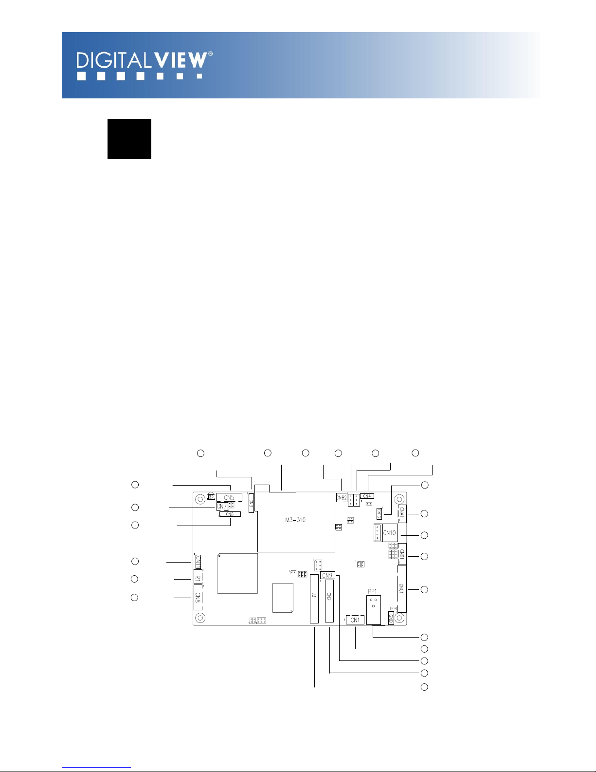
M3-310:
20 Switches and
Buttons connector
(#1 - #8)
1Switches and
Buttons connector
(#9 - #16)
2CF card
socket 3Inverter
Status 4Controller
Status 5Backlight
Status 6Reserved
7USB connector
9Alternative power
out
10 Backlight inverter
11 OSD Control
8Auxiliary power
output
12 Power input (DC 12V)
13 Speaker out (L/R)
14 Alternative line out
15 TTL panel connector
16 LVDS panel connector
19 Reserved
21 480p/720p
18 IR connector
17 Serial port
(For panel)
22 RS-232 port
JA1
JB5
JA3
JP15
JP16
VR1
JP1 JP5
JP2
JP3
JP7
JP6
3V3
5V
JB1
JB2
JB3
LED1 LED2 JP4
1
1
1
1
1
JB6

Page 6 of 36
Summary:
1. Switches and buttons (9 –16 button)
12. Power input (DC +12V)
2. Compact Flash card slot
13. Speaker out (L/R)
3. Inverter status
14. Alternative line out
4. LED1 - Controller status
15. TTL panel connector
5. LED2 - Backlight status
16. LVDS panel connector
6. Reserved
17. Serial port (for panel control)
7. USB connector
18. IR sensor connector
8. Auxiliary power output
19. Reserved
9. Alternative power out
20. Switches and buttons (1 –8 button)
10. Backlight inverter
21. Output resolution (480/720p)
11. OSD control
22. RS-232 port
For detailed pin-outs on all connectors see the tables in Section 5 below

Page 7 of 36
3 Connection Overview
CAUTION: Never connect or disconnect parts of the system when the system
is powered up as this may cause serious damage.
3.1 Prepare for connection
Connection and usage are straightforward. However, during assembly, care
needs to be taken regarding the following:
Ensure parts, especially power and signal cables, match the system. If
you are making your own cables & connectors refer carefully to the
video monitor specifications and the “Connectors, Pin outs & Jumpers”
section in this user guide to ensure the correct pin-to-pin wiring.
Ensure cables have been correctly connected and that connections are
secure.
Screws and fasteners need to be secure, consider using locking glue if
appropriate.
Switches and jumpers are set correctly.
The output signal is compatible with display equipment.
Legal & safety requirements have been met with particular attention to
the likely operating environment. Although the M3-310 is designed to
be fanless in normal conditions some installations and environments
may require additional cooling.
3.2 Basic connection for M3-310
The following summarizes a simple connection:
Connect the inverter (if it is not built-in the panel) to the CCFT lead
connector(s) on the panel.
Plug the inverter cable to CNB1 and CNA1.(if necessary) on the M3-310.
Plug another end to the connector on the inverter.
Note: Different inverter models require different cables and different pin
assignment. Make sure correct cable pin out to match inverter. Using wrong
cable pin out may damage the inverter.
Plug the panel signal cable direct to CN2 (if TTL panel is used) or J3 (if
LVDS panel is used) on the M3-310. Plug the other end of cables on the
LCD panel connector.

Page 8 of 36
CAUTION: Before connecting power ensure all parts are suitably
insulated and there is no risk of short circuit or electrocution. Connect
the power supply (DC 12V @ 1.2A minimum. - ensure correct polarity)
to the M3-310 power input (PP1).
Plug the OSD switch mount cable (p/n:420680260-3) to CNC1 on the
M3-310 and another to the OSD switch mount. (P/N:416100520-3)
For “Auto play with Power On”, short the pin1-2 on JP6
Ensure there is a CF card installed with compatible media loaded.
If the optional buttons are being used connect them to CN6 and CN3

Page 9 of 36
4 System Notes
The following outlines various issues related to the M3-310 and making a
complete system:
LED1/LED2 - The power/status LED indicator shows the following
status of Panel:
Controller LED status (LED1): Backlight LED status (LED2):
RS-232 port –This port supports RS-232 communications for control.
The baud rate must be set to (9600, n,8,1) and record suffix is set to
CR (0DH).
USB –Plug an USB extension cable (P/N:426894600-3). Use a USB
flash drive for content update without removing the CF card. The M3-
310 will reset the power when a USB flash drive is inserted or removed
from the USB connector. (For the details of USB content update, please
refer to the Application note.)
Audio output –This provides speaker out and line out connection.
Master volume is controlled through OSD with buttons connecting to
CN6. For connection, plug a stereo speaker (P/N 230800301) with
stereo cable (P/N 426680900-3) to the connector CN1. If for line out
connection, connect an audio line out cable (P/N 426450300-3) to CN9.
Volume control –To control the loudness of internal speaker, a 47K
Volume Rotary (VR) can be used. Plug the VR extension cable
(P/N:426890510-3) on to the jumper VR1.
Jumpers & Inverter & Panel voltage –pay special attention to the
settings of JA3, JB2 & JB3. The JB2 & JB3 are used for inverter control
(read inverter specification and information on the jumper table to
define the correct settings). The JA3 is used for panel voltage input
(read panel specification and information on the jumper table to define
the correct settings).
Panel State
LED
color
No signal & backlight
off
RED
No signal & backlight
on
ORANGE
With signal &
backlight on
GREEN
Panel State
LED
color
Backlight fault
RED
Backlight normal
GREEN
NOTE: This status is only available
when CNB2 is proper connected and
the panel is support the backlight
status function.

Page 10 of 36
Power supply - Plug the DC 12V power (ensure correct + & -
orientation) in to the connector PP1. The Digital View mating power
cable is (P/N 426013800-3), 160mm. Please read the jumper table in
Section 5 to define the correct settings. Otherwise it may break down
the panel. (Note: Maximum current output to panel: 2A)
Power on - Switch on the M3-310 board and panel by using the OSD
switch mount (P/N 416100520-3) or short Pin1-2 at JP6 for “Auto power
On”.
Infra-red (IR) - Supports IR control with DV remote control handset
(P/N:559000104-3). The IR sensor and cable kit (P/N:446010401-3)
are required. The IR control functions are shown as below.
ATTENTION + Key “3”
(IR enable/disable)
Mute
Repeat
Direct
Track #
Access
OSD on/off
Previous track
Play
Next track
Stop
Pause
Volume Up
Volume Down
Buttons and Touch screen (segment type) –A number of related
accessories are available providing enhanced functionality such as user
buttons and touch screen.
A) Mechanical buttons
Standard MV-switchmount (P/N:416101300-3) for 1-8 buttons
when connected to the button connector CN6 via the standard
switchmount cable (P/N:426451100-3).

Page 11 of 36
Custom made switchmount for 1-16 buttons when connected to
the buttons connector CN6 and CN3 via the standard
switchmount cable (P/N:426451100-3)
B) Touch screen segments
The M3-310 when connected with a LCD interface controller can
output videos on to LCD screen. Button control can be
performed via touch screen for panel sizes of 6.4”, 7”, 8”, 10”,
12”, 15”, 17” and 20”
There is one type of button pattern layouts on the touch screen
available: 8 buttons
(For any special button layout, please contact local sales office.)
Fig. 1 8-buttons for LCD touch screen
C) Button function settings
Whether the buttons are of the mechanical type (on the
standard switchmount or custom made) or the touch screen
segment type, each button function can be programmed with
the DV Studio Software program to perform a VCD player
mode function or specific track select function. (See DV Studio
Software user manual).
The DV Studio Software program is available for free download
from the Digital View website.
Service & Warranty Forfeit: The warranty will be invalid if rework is
performed on the M3-310. The M3-310 is not user serviceable or
repairable.

Page 12 of 36
5 Connectors, pinouts & jumpers
JA1
JB5
JA3
JP15
JP16
VR1
JP1 JP5
JP2
JP3
JP7
JP6
3V3
5V
JB1
JB2
JB3
LED1 LED2 JP4
1
1
1
1
1
JB6
The various connectors are:
Ref
Purpose
Description
CN1
Speaker out (L/R) connector
JST B4B-XH-A
CN2
TTL panel signal
Hirose 40-pin, DF20G-40DP-1V
CN3
Switches and buttons connector
(#9 - #16)
Hirose 1.25mm, 9-pin, DF13-9P-
1.25DSA
CN4
Watchdog programmer connector
(Reserved)
Hirose 1.25mm, 6-pin, DF13-6P-
1.25DSA
CN5
RS-232 port
JST B6B-XH-A
CN6
Switches and buttons connector
(#1 - #8)
Hirose 1.25mm, 9-pin, DF13-9P-
1.25DSA
CN7
Resolution selector
(640x480/1280x720)
JST B2B-XH-A
CN8
Serial control
JST B6B-XH-A
CN9
Alternative audio output
JST B4B-PH-K
CN10
Alternative power out connector
JS-1116-04WS
CN11
Reserved
Hirose 1.25mm, 6-pin, DF13-6P-
1.25DSA
CN12
USB connector
Hirose 1.25mm, 4-pin, DF13-4P-
1.25DSA
CNA1
Auxiliary power output
JST B4B-XH-A
CNB1
Backlight inverter
JST B5B-XH-A
CNB2
Backlight status
JST B2B-XH-A
CNC1
OSD controls
JST B12B-XH-A
PP1
Power input
Molex 43650-0200
IR1
IR sensor connector
JST B3B-XH-A
VR1
External volume control
3x2 header (2.54mm pitch)
J3
LVDS panel signal
Hirose DF13-40DP-1.25DSA
J6
CF card connector
CF-CARD, 25x2Ppin 3M CF-II socket
J7
USB connector
JST B4B-ZR

Page 13 of 36
5.1 Jumpers setting
Ref
Purpose
Note
JA1
For internal testing
1-3 & 2-4 closed, factory set, do not remove
JA3
Panel power voltage select
See panel voltage setting table 1
CAUTION: Incorrect setting will cause panel
damage
JB1
Backlight brightness voltage range
1-2 closed = 3.3V max*
2-3 closed = 5V max
JB2
Backlight inverter on/off control –signal
level
2-3 = On/Off control signal „High‟ = +5V*
1-2 = On/Off control signal „High‟ = +3.3V
Open = On/Off control signal „High‟ = Open
collector
CAUTION: Incorrect setting can damage
inverter.
JB3
Backlight inverter on/off control –polarity
1-2 = control signal „high‟ = CCFT ON*
2-3 = control signal „low‟ = CCFT ON
JB5
Backlight control type selection
1-2 =VR/Digital switch mount control
3-4 =Reserved
5-6 =Reserved
JB6
Backlight status
1-2, 3-4 closed = Backlight status Low –
Normal
1-3, 2-4 closed = Backlight status High –
Normal
Open = Backlight status not used
JP1
Reserved
Reserved for internal programming use (Always
1-2 closed)
JP2
Panel selection
See table 3 below
JP3
Panel selection
See table 3 below
JP4
Detect the watchdog pulse
1-2 closed =Off the detection*
1-2 opened=On the detection
JP5
Panel selection
See table 2 below
JP6
Input power control
Short = External switch control
Open = Switch mount control
JP7
Panel selection
See table 4 below
* Factory default
Table 1: Panel voltage setting
Input voltage via
PP1
Panel Voltage
JA3
Jumper on
board
12VDC
3.3V
3V3 closed
5V
5V closed
CAUTION: Incorrect setting can damage the panel & controller

Page 14 of 36
Table 2: Panel selection (JP5) –Panel model
JP5
Description
Panel
resolution
1-2
3-4
5-6
For WXGA panel
Opened
Opened
Opened
Samsung LTA260W2-L01(1)
1366x768
Opened
Opened
Closed
AU M220EW01(1)
1680x1050
Opened
Closed
Opened
NEC NL12880BC20-02D(1)
1280x800
Opened
Closed
Closed
Sharp LQ315T3LZ24(2)
1366x768
AU Optronics M156XW01 V0(2)
1366x768
For XGA panel
Opened
Opened
Opened
AU M150XN07(1)
1024x768
Opened
Opened
Closed
LG LM150X08-A4(1)
1024x768
Opened
Closed
Opened
Sharp LQ150X1LGB1(2)
1024x768
Sharp LQ150X1LGN2A(2)
1024x768
For VGA panel
Opened
Opened
Opened
LG LP104V2(1)
640x480
Data Image FG080012DNCWAG0Z(1)
640x480
Opened
Opened
Closed
AU Optronics G104VN01(1)
640x480
Opened
Closed
Opened
Sharp LQ10D421(1)
640x480
Others
Opened
Opened
Closed
PrimeView PD104SL5(2)
800x600
AU Optronics A201SN01(2)
800x600
Opened
Closed
Opened
Samsung LTM170ET01(3)
1280x1024
Opened
Closed
Closed
Samsung LTM190M2-L31(3)
1440x900
Closed
Opened
Opened
CPT CLAA102NA0ACW(4)
1024x600
Note: In addition to the above panel support lists, we are on going to support
various panel models for M3-310. Please contact Digital View offices for
supporting your panel that are not listed.
Panel selection (JP2 &JP3) - Resolution
JP2
JP3
Description
Closed
Opened
WXGA
Opened
Closed
XGA
Opened
Opened
VGA
Closed
Closed
Others
Table 4: Panel selection (JP7) –Panel timing:
JA7
Function
Description
1-2
Panel pixel format
Closed : Single Pixel
Opened : Double Pixel
3-4
LVDS data mapping select
Closed : Mapping A (LVDS panel)
Opened : Mapping B (LVDS panel)
Please adjust to get the correct picture. See as
Appendix II for details of mapping A and B.
5-6
Selection of TTL / LVDS
panel connection
Closed : LVDS
Opened : TTL
Page 15 of 36
5.2 Pin Assignment
CN1 –Speaker out (Left / Right)
PIN
SYMBOL
DESCRIPTION
1
GND
Ground
2
L
Left speaker out
3
GND
Ground
4
R
Right speaker out
CN2 –Panel connector (TTL)
PIN
SYMBOL
DESCRIPTION
1
GND
Ground
2
GND
Ground
3
NC
No connection
4
NC
No connection
5
RA0
Data bit R0
6
RA1
Data bit R1
7
RA2
Data bit R2
8
RA3
Data bit R3
9
RA4
Data bit R4
10
RA5
Data bit R5
11
RA6
Data bit R6
12
RA7
Data bit R7
13
GND
Ground
14
GND
Ground
15
NC
No connection
16
NC
No connection
17
GA0
Data bit G0
18
GA1
Data bit G1
19
GA2
Data bit G2
20
GA3
Data bit G3
21
GA4
Data bit G4
22
GA5
Data bit G5
23
GA6
Data bit G6
24
GA7
Data bit G7
25
GND
Ground
26
GND
Ground
27
NC
No connection
28
NC
No connection
29
BA0
Data bit B0
30
BA1
Data bit B1
31
BA2
Data bit B2
32
BA3
Data bit B3
33
BA4
Data bit B4
34
BA5
Data bit B5
35
BA6
Data bit B6
36
BA7
Data bit B7
37
GND
Ground
38
GND
Ground
39
VS
Vertical sync
40
CLK
Dot clock
41
HS
Horizontal sync
42
DE
Display enable
43
PWR
Power down control signal (5v
TTL)
44
VLCD
Panel power supply (3,3V/5V)
(selected by JA3 )

Page 16 of 36
45
VLCD
Panel power supply (3,3V/5V)
(selected by JA3)
46
VLCD
Panel power supply (3,3V/5V)
(selected by JA3)
47
NC
No connection
48
NC
No connection
49
NC
No connection
50
NC
No connection
CN3 –Switches and buttons (#9 - #16)
PIN
SYMBOL
DESCRIPTION
1
SW9
Button 9
2
SW10
Button 10
3
SW11
Button 11
4
SW12
Button 12
5
SW13
Button 13
6
SW14
Button 14
7
SW15
Button 15
8
SW16
Button 16
9
GND
Ground
CN4 –Watchdog programmer connector
CN5 –RS-232 port
PIN
SYMBOL
DESCRIPTION
1
NC
No connection
2
NC
No connection
3
5V
+5V
4
Tx
Tx Data
5
GND
GND
6
Rx
Rx Data
CN6 –Switches and buttons (#1 - #8)
PIN
SYMBOL
DESCRIPTION
1
SW1
Button 1
2
SW2
Button 2
3
SW3
Button 3
4
SW4
Button 4
5
SW5
Button 5
6
SW6
Button 6
7
SW7
Button 7
8
SW8
Button 8
9
GND
Ground
CN7 –Resolution selector
PIN
SYMBOL
DESCRIPTION
1
SYSTEM
1-2 close: 1280x720
1-2 open: 640x480
2
GND
Ground

Page 17 of 36
CN8 –Serial control (for Panel)
PIN
SYMBOL
DESCRIPTION
1
SDATA
Reserved
2
SCLK
Reserved
3
Vcc
+5V
4
TxD
Tx Data
5
GND
GND
6
RxD
Rx Data
CN9 - Alternative speaker output
PIN
SYMBOL
DESCRIPTION
1
GND
Ground
2
AUDIO_L
Audio left channel output
3
GND
Ground
4
AUDIO_R
Audio right channel output
CN10 - Alternative power out
PIN
SYMBOL
DESCRIPTION
1
VCC
+5V out
2
GND
Ground
3
GND
Ground
4
+12V
+12V out
CN11 –Reserved
CNA1 - Alternative power output
PIN
SYMBOL
DESCRIPTION
1
AUX POWER
+12V DC
2
GND
Ground
3
GND
Ground
4
AUX 5V
+5V DC
CNB1 - Backlight inverter
PIN
SYMBOL
DESCRIPTION
1
GND
Ground
2
VBKL
Backlight power supply, +12VDC
3
BLCTRL
Backlight On/Off control signal
4
BVR_WIP
Backlight brightness VR pin WIP
5
BVR_A
Backlight brightness VR pin A
CNC1 - Function control switch
PIN
SYMBOL
DESCRIPTION
1
PSWIN
Power button A

Page 18 of 36
2
SW_ON
Power button B
3
BVR_A
Backlight Brightness VR pin A
4
BVR_WIP
Backlight Brightness R pin WIP
5
BVR_B
Backlight Brightness VR pin B
(470 ohm resistor to +5V Vcc)
6
GND
Ground
7
MENU
OSD menu
8
-/LEFT
OSD -/Left
9
+/RIGHT
OSD +/Right
10
SEL_DN
OSD Select down
11
SEL_UP
OSD Select up
12
NC
No connection
LED1 - Controller status LED connector
PIN
DESCRIPTION
1
Green LED pin (anode)
2
LED pin common (cathode)
3
Red LED pin (anode)
LED2 - Backlight status LED connector
PIN
DESCRIPTION
1
Green LED pin (anode)
2
LED pin common (cathode)
3
Red LED pin (anode)
IR1 - IR connector
PIN
SYMBOL
DESCRIPTION
1
GND
Ground
2
STDBY_VCC
Stand by voltage
3
IR DATA
IR data
J3 - Panel connector (LVDS)
PIN
SYMBOL
DESCRIPTION
1
TXA0+
Positive differential LVDS data
bit A0
2
TXA0-
Negative differential LVDS data
bit A0
3
TXA1+
Positive differential LVDS data
bit A1
4
TXA1-
Negative differential LVDS data
bit A1
5
NC
No connection
6
NC
No connection
7
TXA2+
Positive differential LVDS data
bit A2
8
TXA2-
Negative differential LVDS data
bit A2
9
TXA3+
Positive differential LVDS data
bit A3
10
TXA3-
Negative differential LVDS data
bit A3
11
GND
Ground

Page 19 of 36
12
GND
Ground
13
TXAC+
Positive LVDS clock for A
channel
14
TXAC-
Negative LVDS clock for A
channel
15
GND
Ground
16
GND
Ground
17
TXB0+
Positive differential LVDS data
bit B0
18
TXB0-
Negative differential LVDS data
bit B0
19
TXB1+
Positive differential LVDS data
bit B1
20
TXB1-
Negative differential LVDS data
bit B1
21
NC
No connection
22
NC
No connection
23
TXB2+
Positive differential LVDS data
bit B2
24
TXB2-
Negative differential LVDS data
bit B2
25
TXB3+
Positive differential LVDS data
bit B3
26
TXB3-
Negative differential LVDS data
bit B3
27
GND
Ground
28
GND
Ground
29
TXBC+
Positive LVDS clock for B
channel
30
TXBC-
Negative LVDS clock for B
channel
31
GND
Ground
32
GND
Ground
33
VDD (3,3V/5V)
Panel power supply (3,3V/5V)
(selected by JA3)
34
VDD (3,3V/5V)
Panel power supply (3,3V/5V)
(selected by JA3)
35
VDD (3,3V/5V)
Panel power supply (3,3V/5V)
(selected by JA3)
36
VDD (3,3V/5V)
Panel power supply (3,3V/5V)
(selected by JA3)
37
NC
No connection
38
NC
No connection
39
NC
No connection
40
NC
No connection
J6 –Compact Flash card connector
PIN
SYMBOL
DESCRIPTION
1
GND
Ground
2
D3
Data bit 3
3
D4
Data bit 4
4
D5
Data bit 5
5
D6
Data bit 6
6
D7
Data bit 7
7
/CE1
Card enable 1
8
GND
Ground
9
GND
Ground
10
GND
Ground
11
GND
Ground
12
GND
Ground
13
VCC
+5V

Page 20 of 36
14
GND
Ground
15
GND
Ground
16
GND
Ground
17
GND
Ground
18
A2
Address bit 2
19
A1
Address bit 1
20
A0
Address bit 0
21
D0
Data bit B3
22
D1
Data bit B4
23
D2
Data bit B5
24
IOCS16
IOCS16
25
/CD2
Card detect pin 2
26
/CD1
Card detect pin 1
27
D11
No connection
28
D12
No connection
29
D13
No connection
30
D14
No connection
31
D15
No connection
32
/CE2
Card enable 2
33
GND
Ground
34
/RD
Memory read strobe
35
/WR
Memory write strobe
36
/WE
No connection
37
IRQ
Interrupt request
38
VCC
+5V
39
/CSEL
Chip SEL
40
NC
No connection
41
RESET
System reset
42
IORDY
IO Ready
43
NC
No connection
44
NC
No connection
45
/DASP
DASP
46
/PDIAG
PDIAG
47
D8
No connection
48
D9
No connection
49
D10
No connection
50
GND
Ground
J7 - USB connector
PIN
SYMBOL
DESCRIPTION
1
UVCC
USB - VCC
2
D-
-VE USB Data
3
D+
+VE USB Data
4
GND
Ground
J8 - M3-310 debugger
PP1 - Main power input
PIN
SYMBOL
DESCRIPTION
1
+12_CENTER
+12V DC in center pin
2
GND
Ground
VR1 –External volume control
PIN
DESCRIPTION
1-3, 2-4
Close (Factory default)
Open (for connection with 47K VR ext. cable (p/n:426890500-3))
Table of contents
Other digitalview Media Player manuals


