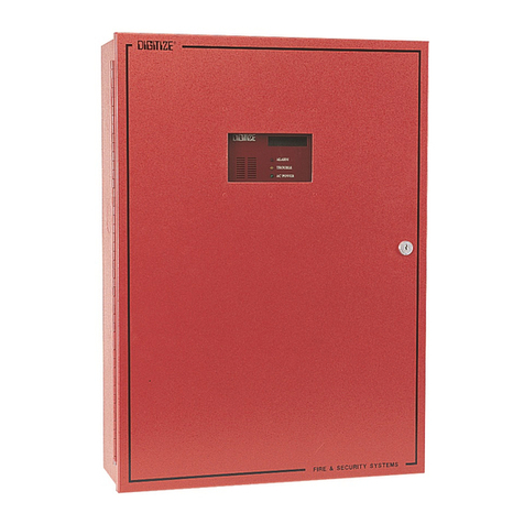
DIGITIZE System 3000 User manual

Digitize, Inc.
158 Edison Road
Lake Hopatcong, NJ 07849-2217
The Digitize logo (stylized) is a registered trademark of Digitize, Inc.

PROPRIETARY NOTICE
AND DISCLAIMER
DIGITIZE, INC.
158 EDISON ROAD
LAKE HOPATCONG, NJ 07849-2217
PH: (973) 663-1011
FAX: (973) 663-4333
E-Mail: info@digitize-inc.com
Website: http://www.digitize-inc.com
This manual has been prepared by DIGITIZE, INC. for use by its licensees,
distributors and customers. The information contained herein is the property of
DIGITIZE, INC. and may not be copied, disclosed or reproduced, in whole or
in part, without the prior written approval of DIGITIZE, INC. Any unauthorized
disclosure to, or use of the enclosed information by, unauthorized third
persons shall void any and all representations, warranties and obligations on
the part of DIGITIZE, INC.
DIGITIZE, INC. reserves the right to make changes to the specifications and
material contained herein without prior notice. The information and/or
examples (including, but not limited to circuitry, wiring diagrams,
programming, the operation or use shown) described in this manual are
intended solely to illustrate the operating principles of the particular product.
They are not a warranty, representation or guarantee that a particular example
or use shown will perform in a particular situation. They are given for
illustration purposes only. DIGITIZE, INC. shall not be responsible, nor does it
represent, that any example of illustration will perform in a particular
environment or practice unless it specifically makes a representation to that
effect.
The material set forth herein is for informational purposes only, and
DIGITIZE, INC. assumes no patent liability with respect to any information
or illustrations contained herein.

FCC NOTICE
In compliance with Paragraph 15.105 of the FCC Rules and Regulations, the
following notice is provided.
NOTE: This equipment has been tested and found to comply with the limits for
a Class A digital device, pursuant to Part 15 of the FCC Rules. These limits are
designed to provide reasonable protection against harmful interference when the
equipment is operated in a commercial environment. This equipment generates,
uses, and can radiate radio frequency energy, and, if not installed and used in
accordance with the instruction manual, may cause interference to radio
communications. Operation of this equipment in a residential area is likely to
cause interference, in which case the user will be required to correct the
interference at his own expense.
P/N 700120 Rev C

TABLE OF CONTENT
1.0 Preparation for SYSTEM Upgrade...................................1-1
1.1 Tools..............................................................................................................1-1
1.2 PCB Rework..................................................................................................1-1
1.3 Preparing the SYSTEM.................................................................................1-1
2.0 SYSTEM 3000 disassembly ................................................2-1
3.0 3505 ASSEMBLY ................................................................3-1
3.1 BRACKET LOCK ASSEMBLY ..................................................................3-1
3.2 PRINTER MECH SLIDE ASSEMBLY .......................................................3-2
3.3 FISH PAPER INSTALLATION...................................................................3-3
3.4 PRINTER SLIDE AND 3505 FRONT PANEL ASSEMBLY .....................3-4
3.5 REAR PANEL ASSEMBLY ........................................................................3-6
3.6 CARD INSTALLATION..............................................................................3-7
3.7 PRINTER MECH INSTALLATION............................................................3-10
3.8 POWERING UP SYSTEM 3505 ..................................................................3-12
APPENDIX A A-1


SYSTEM 3000 to 3505 CONVERSION MANUAL
DIGITIZE, INC. 700254-0001 REV B 02/04
Specifications Subject to Change Without Notice
1-1
1.0 Preparation for SYSTEM Upgrade:
1.1 Tools:
The following tools are required to perform the system upgrade:
1. Assorted slotted screw drivers.
2. Assorted Phillips head screw drivers.
3. 11/32 open end wrench.
4. Diagonal cutters.
5. 7/64 Allen wrench.
6. Digital Volt/Ohm meter.
7. 3/16 Nut driver.
8. Solder Iron, Solder, Jumper Wire 22 or 24 ga (See 1.2 PCB Rework).
1.2 PCB Rework
Before preceding with the disassembling, of the SYSTEM 3000, check for 24VDC at
Pin 1 J6 Aux Port, to chassis, of rear panel, to determine if you need to update
(rework) the PCB. If 24VDC is not present, continue to Appendix A. If the 24VDC
is present, continue with the conversion and disregard Appendix A.
1.3 Preparing the SYSTEM
Turn off the power to the SYSTEM being upgraded, and remove both AC and DC
power sources. Refer FIG 1
FIG 1
Optional
Configuration Cards
DC Power
Input
AC Switch and
Power Cord
Recommended before upgrading your SYSTEM 3000 to a 3505
Digitize recommends using the Win3505 program to save the User Text from your
system 3000/3500 before the system is upgraded. This will eliminate having to
manually enter any system configurations. The system configurations consist of:
Multiplex, Network, Radio Box W/ Neg box, Dialer accounts W/ Neg dialer etc.
The Win3505 also allows the editing of the user text pages from 3000/3500 16 X 3 page
format to 3505 24 X 2 page format.
SYSTEM 3000 with CPU5 configuration can not be saved with WIN 3505.
SYSTEM 3000 with CPU5 will require a new EE2 PROM Board 400349-0003 for
MEM-600 chips. The 3000 CPU5 400349 board will not work in a SYSTEM 3505.

SYSTEM 3000 to 3505 CONVERSION MANUAL
DIGITIZE, INC. 700254-0001 REV B 02/04
Specifications Subject to Change Without Notice
1-2
Remove all optional configuration cards, mounting hardware and power plug. (Refer to
FIG2). Note which Port # each configuration card was in. Save the hardware to re-install
configuration cards on the new rear panel, Step 3.8.3.
FIG 2

SYSTEM 3000 to 3505 CONVERSION MANUAL
DIGITIZE, INC. 700254-0001 REV B 02/04
Specifications Subject to Change Without Notice
2-1
2.0 SYSTEM 3000 Disassembly
FIG1a FIG2a
2.1 Using a flat head screw driver, loosen the four screws holding the system cover in
place. Refer to FIG 1a &2a
2.2 With the cover removed, pull the printer mechanism fully out. Then disconnect the
printer MECH ribbon and power cable from the printer card. Disconnect the ground
wire located on the side of the card cage. Refer to FIG 3a
FIG 3a
GROUND WIRE
RIBBON CABLE
POWER CABLE

SYSTEM 3000 to 3505 CONVERSION MANUAL
DIGITIZE, INC. 700254-0001 REV B 02/04
Specifications Subject to Change Without Notice
2-2
2.3 Unscrew the pan head stopping screw with hex nut and star washer then remove the
printer MECH. Refer to 4a
FIG 4a
2.4 Remove the four pan head screws holding the printer MECH support bracket.
Refer to FIG 5a
FIG5a
2.5 Remove all the PC cards from the Card Cage and disconnect the ribbon cables from
the rear panel. Refer to FIG 6a & 6b. Note: Save the I/O cards and EE2 PROM for
re-installation later.
FIG6a FIG6b
Stopping
Screw

SYSTEM 3000 to 3505 CONVERSION MANUAL
DIGITIZE, INC. 700254-0001 REV B 02/04
Specifications Subject to Change Without Notice
2-3
2.6 Remove the slotted screws holding the rear panel in place. To remove the rear panel,
lift up to disengage it from the motherboard. Refer to FIG 7a & 7b
2.6.1 Remove any additional hardware if installed from the rear panel and save for
installation on the new rear panel.
1. SST Relays and spring clips, K0 and K1.
2. Any 26 pin ribbon cable and hardware, ZONES 1-512, ZONES 513-1024, TCI,
or POINT OUTPUT.
3. If so equipped the AUX PWR OUT cable will not be needed in the 3505.
FIG 7b
2.7 Disconnect the cable between the 9000UF 50V RADIAL CAP (P/N: 900111-0019)
and the Cable CF2 W/ Transformer assembly (P/N: 450294-0004). Refer to FIG 8a
2.7.1 Remove the four screws holding the transformer in place. Refer to FIG 8b
LIFT UP
FIG 7a
REMOVE
REMOVE

SYSTEM 3000 to 3505 CONVERSION MANUAL
DIGITIZE, INC. 700254-0001 REV B 02/04
Specifications Subject to Change Without Notice
2-4
2.7.2 Remove the three screws holding the CAP bracket in place. Refer to FIG 8c
FIG8a FIG8b FIG8c
2.8 Remove the Male Cabinet Latch by unscrewing the flat head screws located on the
bottom of the system. Refer to FIG 9a and 9b
FIG9a FIG9b
2.9 Remove the front panel by unscrewing the two machine screws located on the
bottom of the chassis. See FIG 10a. Save for later.
FIG 10a

SYSTEM 3000 to 3505 CONVERSION MANUAL
DIGITIZE, INC. 700254-0001 REV B 02/04
Specifications Subject to Change Without Notice
2-5
2.10 Then remove the 3 hex nuts located on the inside. Refer to FIG 10b. Save hex nuts
for re-assembly. Remove front panel assembly.
FIG 10b
2.11 The SYSTEM is now ready to be rebuilt. Refer to FIG 10c
FIG 10c


SYSTEM 3000 to 3505 CONVERSION MANUAL
DIGITIZE, INC. 700254-0001 REV B 02/04
Specifications Subject to Change Without Notice
3-1
3.0 3505 ASSEMBLY
3.1 BRACKET LOCK ASSEMBLY
3.1.1 Attach the Male Cabinet Latch(Item 2) to the Bracket Lock(Item 1) using
Two of each, 4-40x5/16 screws (item 3), #4 flat washer (item 4) and #4
lock washer (item 5). Refer to DWG 1, FIG 1a &1b
DWG 1
FIG1a FIG1b
3.1.2 Screw the 6-32x1.128 Socket Head screw (item 6), with one #6 lock
washer (items 9) and one #6 flat washer (item 10), into the Bracket Lock
(Item 1). Slide the assembled bracket lock to the notch on the lower slide
rod (item 8). Lightly tighten Socket Head screw to hold in place.
NOTE: The notch in the rod is placed in the back of the system, so the male stop should
be facing the system’s front. Refer to DWG 1 & FIG 1c
Item #3
Item #5
Item #4
Item #6
Item #9
Item #10
Item #2
Item #1

SYSTEM 3000 to 3505 CONVERSION MANUAL
DIGITIZE, INC. 700254-0001 REV B 02/04
Specifications Subject to Change Without Notice
3-2
FIG 1c
3.2 PRINTER MECH SLIDE ASSEMBLY
3.2.1 To attach the female cabinet latch (item 11), to the slide bracket (item
12), use two each, 4-40x7/16 screws (item 2), #4 Split washer (item 3)
and #4 flat washer (item 4). Refer to DWG 2.
DWG 2
12
2, 3, 4
11

SYSTEM 3000 to 3505 CONVERSION MANUAL
DIGITIZE, INC. 700254-0001 REV B 02/04
Specifications Subject to Change Without Notice
3-3
3.2.2 Slide the top rod, item 1, through the upper nylon insert, and the lower
rod, item 11, into the bottom nylon insert. Refer FIG 1d
FIG 1d
NOTE: The slide rails ends are different thread sizes, with the larger #8 thread screwing on to the front
panel, and the smaller #6 thread to the back of the chassis. There are no markings at this time,
so a visual inspection is needed to determine how the rails are placed. See DWG 3
DWG 3
3.3 FISH PAPER INSTALLATION
3.3.1 From the bottom of the chassis, un-screw the 4 flat head screws to remove
card cage. See FIG 2a
Front of Chassis
Back of Chassis

SYSTEM 3000 to 3505 CONVERSION MANUAL
DIGITIZE, INC. 700254-0001 REV B 02/04
Specifications Subject to Change Without Notice
3-4
FIG 2a
3.3.2 Remove the top 2 pan head screws and washers from the PWR side of the
card cage. Attach the protective fish paper to the card cage using the 2
pan head screws and washers. See FIG 2b & 2c
FIG 2b FIG 2c
3.3.3 Re-install the card cage to the chassis using the original 4 flat head screws.
See FIG 2d
FIG 2d
3.4 PRINTER SLIDE AND THE 3505 FRONT PANEL ASSEMBLY.
3.4.1 Place the slide assembly in side the chassis, checking for any gaps
between the front of the chasse and the rails. If a gap is present, then use
#8 flat washers between the chassis and the rails. Put the new 3505 front
panel in place but do not attach. See FIG 3a & 3b

SYSTEM 3000 to 3505 CONVERSION MANUAL
DIGITIZE, INC. 700254-0001 REV B 02/04
Specifications Subject to Change Without Notice
3-5
FIG 3a FIG 3b
3.4.2 Rotate the rails to attach them to the front panel. Tighten the top rail by
hand first, and then begin to tighten the bottom rail. Tighten securely. See
FIG 3c
FIG3c
3.4.3 Attach the bracket lock to the rail, by tightening the 6-32x1.128 Socket
Head screw, into the notch on the rail, using a 7/64 Allen wrench to
secure. See FIG 3d.
FIG 3d

SYSTEM 3000 to 3505 CONVERSION MANUAL
DIGITIZE, INC. 700254-0001 REV B 02/04
Specifications Subject to Change Without Notice
3-6
3.4.4 Once the rails are in place, attach the front panel with the 8-32 Kept Nut
on the inside upper right corner of the panel. Use 2, #6 flat head screws to
attach the front panel from beneath the chassis. See FIG 3e & 3f
FIG3e FIG3f
3.5 REAR PANEL ASSEMBLY
Install any additional hardware (from step 2.6.1) on the new rear panel.
1. SST Relays and spring clips, K0 and K1.
2. Any 26 pin ribbon cable and hardware, ZONES 1-512, ZONES 513-1024, TCI,
or POINT OUTPUT.
3. If so equipped the AUX PWR OUT cable will not be needed in the 3505.
3.5.1 Slide the rear panel into place on the mother board, gently pushing down to
set it snug in the slot. See FIG 4a
FIG 4a
3.5.2 Secure the rear panel to the chassis using 2, #6-32 x 1/2 screw, 2 #6-32 x
5/8 screws, 4 #6 flat washers and 4 #6 lock washers. The 2, #6-32 x 5/8
screws and washers are used, on the right side, with the sliding rails. The 2,
#6-32x1/2 screws and washers are used, on the left side, of the rear panel. See
FIG 4b &4c
FIG4b FIG4c
Other manuals for System 3000
2
This manual suits for next models
2
Table of contents
Other DIGITIZE Security System manuals