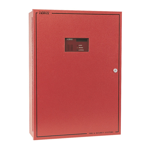
DIGITIZE System 3505 User manual

Digitize, Inc.
158 Edison Road
Lake Hopatcong, New Jersey 07849- 17
Tel: (973) 663-1011
Fax: (973) 663-4333 Part Number: 700 51-0001
E-mail: info@digitize-inc.com Revision: B
Website: http://www.digitize-inc.com Issue Date: 04/0
SYSTEM 3505
Remote Alarm Terminal Option
OPERATION
MAN AL

2 DIGITIZE, INC. 700251 REV B 04/02
Specifications Subject to Change Without Notice
Table of Contents
Overview......................................................................................................................................... 3
Features .......................................................................................................................................... 3
Test Mode ................................................................................................................................... 4
Roll key ....................................................................................................................................... 4
SST Transmit ............................................................................................................................. 4
Acknowledgement...................................................................................................................... 5
Police Slave unit ......................................................................................................................... 8
Automation Link....................................................................................................................... 9
Alarm queue size...................................................................................................................... 10
APPENDIX A DISPLAY ........................................................................................................ 11
APPENDIX B INSTALLATION DRAWINGS .................................................................... 12

DIGITIZE, INC. 700251 REV B 04/02 3
Specifications Subject to Change Without Notice
Remote Alarm Terminal Mode
For
SYSTEM 3505
Overview
The SYSTEM 3505 can support a Remote Alarm Terminal (RAT) mode of operation.
This mode of operation is designed for customers who use the SYSTEM 3505 only
for monitoring Telegraphic alarms. Multiple SYSTEM 3505 units can be configured
in a network environment to be part of the SYSTEM 3505 Remote Alarm Terminal
system.
This mode of operation is designed to replace the original Remote Alarm Terminal units,
sold primarily to large cities, with up to 140 Alarm Box Circuits.
This mode of operation provides features such as placing a circuit in “Test Mode”,
bypassing a circuit, rolling the display, etc.
Since the Remote Alarm Terminal mode is an option on the standard SYSTEM 3505,
even communities with as few as one-telegraph circuit can now utilize this mode of
operation.
The Remote Alarm Terminal mode Network presumes that the Master SYSTEM 3505-
RAT is connected to the telegraph loop circuit via the 100MA or 4VDC buss. The
Master unit collects the Make/Break signals from the telegraph circuit loops and converts
them to serial data strings. These data strings are routed to all the SYSTEM 3505-RAT
slaves via a dedicated supervised serial “code” data line. Communication between
Master and Slave units for the purpose of transferring system trouble information, SST
transmission requests is done via the “Network” data line.
Refer to the Digitize SYSTEM 3505 Manual for details on other functions of the
RAT product not covered here.
Digitize can customize the features in your Remote Alarm Terminal to fit your needs.
Features
Items described here are based on having options such a Radio Beep, SST, Remote Alarm
Terminal, Network, dash and All Out options installed in the SYSTEM 3505. The Test Mode,

4 DIGITIZE, INC. 700251 REV B 04/02
Specifications Subject to Change Without Notice
Engine OK, Engine Repeat are features assigned to Custom Program #0101 only. Please advise
your sales representative if you wish to include this or other features in your system.
Test Mode
1. Any circuit can be placed in test mode by activating two taps prior to pulling the
box to be tested. The SYSTEM 3505 will substitute the word ‘TEST’ for ‘BOX’
when decoding a box on a circuit placed in a test mode. You must wait at least 5
seconds from the time you release the key on the second tap, until you pull the
box to be tested. Caution should be used to verify that a ‘real’ box does not come
in while you are in the test mode, waiting for the test box to be pulled. It is
recommended that you either communicate with the field personnel ad be advised
what box is to be pulled, or make it the responsibility of the field tech to notify
fire dispatch should he “hear” another box activation while waiting to pull the test
box.
. Once a box is placed in the test mode, a timer is displayed on the right end of the
circuit line. This timer counts down from 180 seconds. Once the test box is
pulled, the circuit shall remain in the test mode until 180 seconds lapses, or four
rounds are decoded with the last two boxes matching. Once this happens, and the
decoding ends, the test count will automatically go to zero, concluding the test
mode.
3. The test mode will also automatically end if there is no new activity on the circuit
for thirty seconds.
4. To start the cycle over again, the field personnel must tap two on the circuit again.
5. The test mode can be ended at any time by a single tap on the circuit already in
the test mode.
Roll key
1. You can only ROLL a box if there is a minimum of two circuits being displayed.
. The ROLL key allows you to take whatever telegraph box is on the top line
(printing line) and ROLL it to the bottom of the stack. This will cause the next
box in line, to now be the top box on the display, thus printing its box rounds.
The third box will be the second and so on.
3. Once a Rolled box makes its way back to the top line, the word “Rolled” will be
printed on the thermal paper to indicate that this box has previously at least
printed some of the rounds.
SST Transmit
1. Any Remote Alarm Terminal may initiate a box transmission. The process is as
follows:
a. Enter desired Box number to be transmitted. For a box containing ten
blows as the first digit, enter a “0”, then the rest of the box. For example
box 10-1 3 would be entered as 01 3. Alternatively for a ten, you can
enter the box as 10-1 3. A delay that is longer then an inter digit, but
shorter then an end of round will occur between the ten and the rest of the
box number in either of the two methods indicated.

DIGITIZE, INC. 700251 REV B 04/02 5
Specifications Subject to Change Without Notice
b. For boxes separated by a delay, enter a “-“. For example 345- 3. The
transmitter will transmit 345, pause, and then transmit 3.
c. Once the first desired box number is entered, the system will change the
Soft Key selection to include “LOAD BOX”. When you have the desired
box number entered, press the “LOAD BOX” soft key. The “TIME” line
of the display will now indicate “n RNDS BOX xxxxxxxxx”, where
xxxxxxxxx is the desired box number entered and n rounds is the preset
desired number of rounds that the system was set up for.
d. When “LOAD BOX” is pressed, several other soft keys will appear. At
this point you can press either the “XMIT FAST”, “XMIT SLOW”, “ALL
OUT” or “RADIO BEEP”. You can also enter a numeric number if you
want to change the number of rounds from 1 to 9. Entering a “0” for the
number of rounds will send continuous rounds until the STOP key is
pressed.
e. To send an alert tone, press and hold the Radio Beep key for the desired
duration of the radio beep signal.
f. At this point you would want to press one of the Transmit keys.
. To abort the transmission, press the STOP key.
3. In order to properly send SST information from a Slave RAT, the Network data
link must be operational. I.e. the SYSTEM must not have a Network Link down
message for your particular Slave unit. In case your Network link is down (a fault
condition), you can always activate a Box transmission directly from the Master
RAT unit.
4. For Custom Program #0101, pressing the Transmit key at any slave SYSTEM
3505, causes the actual transmission to occur at the master unit.
Acknowledgement
The overall decoding system has been set up to allow Acknowledgement from any
RAT. When you press ACK at any RAT, a signal is routed via the Network data
link to advise all other RAT units that an ACK was pressed. If your system
contains two independent decoding halves i.e. a Right side and a Left side, then
the XACK feature is used to cross the ACK from the originating system to the
opposite system.
Acknowledgment of a Box number is required whenever three or more rounds are
decoded, where the next to last round and the round prior to that have decoded the
identical box number. No ACK is required under the same condition if the circuit
is in a test mode or is a mutual aid circuit.
The CLR indication will indicate ACK in reverse video whenever the top box decode
line need for the operator to ACK the box. After pressing ACK at the local RAT,
or receiving an ACK from another RAT, the reverse video ACK will change to a
CLR indication.

6 DIGITIZE, INC. 700251 REV B 04/02
Specifications Subject to Change Without Notice
Special features for SYSTEM 3505 with Custom Program #0101.
1. Whenever Box # 3 is decoded (3 taps), The thermal printout will print “ENGINE
XX OK” per table 1. I.e. decoding 3 taps on Circuit #63 will print “ENGINE
OK”.
. Whenever Box # 5 is decoded (5 taps), The thermal printout will print “ENGINE
XX REPEAT” per table 1. I.e. decoding 3 taps on Circuit #63 will print
“ENGINE REPEAT”.
CIRCUIT # ENGINE Co.
63 0
0 03
44 04
8 05
15 07
04 08
48 09
55 10
36 14
69 16
4 17
30 18
39 0
31 1
11
5 4
56 8
51 9
4 30
16 3
77 33
6 37
74 39
14 41
13 4
57 48
59 49
1 50
46 51
79 5
5 53
3 55
9 56
Table 1. Circuit Vs. Engine

DIGITIZE, INC. 700251 REV B 04/02 7
Specifications Subject to Change Without Notice
The display screen indicates “Engine 8 OK” should three taps be decoded on CKT
56.
Whenever the radio beep is activated on any slave or the master SYSTEM 3505, the
Master SYSTEM 3505 will indicate that the radio beep is active. If the radio beep
signal is activated for more then ten seconds, the Master RAT will automatically kill
the radio beep signal. A printed message will advise you that the signal has been
terminated. The beep ON message shall remain on the display until the input
condition is cleared. For Custom #0101, excludes Slave # located in Police Hdqtrs.
When two or more rounds result in the same number being decoded, the word Read
will appear on the display. If the circuit was in the test mode, then the word TEST
will be displayed in lieu of READ. Pressing clear will clear the first box on the
display. The “3” on the top right of the display indicates the top line will auto clear in
3 seconds.

8 DIGITIZE, INC. 700251 REV B 04/02
Specifications Subject to Change Without Notice
Circuits used for Mutual aid, display the city/town name whenever anything is being
decoded on the circuit. Mutual aid circuits do not display READ when two or more
rounds agree.
Indicates a problem with the Battery backup to your RAT unit. Since the SYSTEM
error number is 1, this indicates that the problem is at the Master unit. The same
fault condition at say Slave # would result in a SYSTEM 00 1 being displayed.
Slave 3 would be SYSTEM 300 1.
This message indicates that Slave #1 has a supervision error for the telegraph data
serial line. This error indicates that NO TELEGRAPH boxes will decode at this
terminal. The account number is 10047 for Slave 1, 0047 for Slave and 30047 for
Slave 3.
The Master RAT will display the messages noted above if the Network link is down
to the noted Slave RAT units. Any Slave unit still connected to the Master will
display the same Trouble condition.
Police Slave unit
Slave #3 is to be used in an emergency should the dispatch facility at the Fenway
need to be abandoned. The same features as are available at the Fenway will be
available at Slave #3 except for the beep tone. All box decoding including test mode
will be functional. SST transmission will also be provided.

DIGITIZE, INC. 700251 REV B 04/02 9
Specifications Subject to Change Without Notice
Slave #3 is located remotely in the BPD. This unit is controlled via the right or the
left main rack system. The rack feeding this slave will have a red LED activated on
the right or left main rack. There are three cable pairs running between BFD and
BPD. One cable pair is used to run Network data information, one for Code data and
a third to control a relay selecting which main rack is used to feed slave #3.
Slave #3 will hunt between the left and right main rack until it finds a good code data
line. Once a signal if found, slave #3 will remain on that side until manually
requested to switch, or a failure is detected on the code data line.
Both the Network and code data lines are buffered from the data lines used within the
BFD dispatch center. Thus a problem with these lines will not effect the dispatch
center operation.
Supervision of slave #3 is via the Left or Right rack, depending on which rack is
controlling this slave unit. Any error messages relating to slave #3 will be displayed
on the left or right system only (not both). When slave #3 switches, the rack no
longer feeding this unit will restore any error message associated with this unit. The
new left or right unit now controlling slave #3 will now take over and display any
error messages.
Automation Link
Each of the main racks is set up to send data to the computer for the purpose of data
logging. Each main rack supervises its link to the automation system. The data is
logged only once, although sent by booth racks. If either the right or the left side
indicates that an automation error exists, this indicates that that side (right or left) is
not communicating with the data logging system. However the data logging PC
should still be receiving and recording data. If both the right and left systems report
an automation error, then no data is being logged or recorded. Check the PC to verify
that it is still running the data logging software. An automation link down signal will
not hamper any other feature of the overall alarm monitoring, decoding or
transmission of a telegraph box.
Automation link down error message

10 DIGITIZE, INC. 700251 REV B 04/02
Specifications Subject to Change Without Notice
Alarm queue size
The RAT units have two alarm queues. One queue is used to decode telegraph boxes.
The second queue is used to hold other system errors. The telegraph decode queue
can hold twenty telegraph boxes. Up to six telegraph boxes can be displayed on the
RAT screen at any one time. The additional fourteen will only appear on the display
when older boxes have been cleared from the display. The upper left corner of the
RAT display will indicate whenever the alarm queue is holding more then 6 boxes.
I.e. if one is displayed, then there are 7 telegraph boxes in the queue. The maximum
number of boxes to be displayed in this indicator is 14. This condition should be
avoided, as no additional boxes will be decoded until older boxes are cleared from the
RAT.

DIGITIZE, INC. 700251 REV B 04/02 11
Specifications Subject to Change Without Notice
APPENDIX A
DISPLAY
Press to
roll top
telegraph
box to
bottom of
cue.
Bypassed CKT’s will not decode
CKT 3 & 101 shown. Each
SYSTEM 3505 bypasses its own
circuits. Enter desired circuit number,
press BYPASS/NORMAL as needed.
Remaining time in seconds,
until the SYSTEM 3505 auto
clears. May be turned OFF
via 1 9 SET.
Current date and time
Reverse Video
indicates ACK
required.
Mutual AID CKT
displays town name
CLR
indicates
top box
ready to be
cleared.
When
displayed,
indicates
SYSTEM
3505 may be
placed in the
sleep mode.
Press History to
view the last 478
conditions.
Press STATUS to
print all active events.
System
error
conditions
Time that
the
condition
was first
reported.

12 DIGITIZE, INC. 700251 REV B 04/02
Specifications Subject to Change Without Notice
APPENDIX B
INSTALLATION DRAWINGS
Other manuals for System 3505
3
Table of contents
Other DIGITIZE Security System manuals