DigiTrak F5 SST User manual


DIGITAL CONTROL INCORPORATED
2 DigiTrak®F5®SST®Operator’s Manual
403-3500-00-C1, Oct 2013
© 2011–2013 by Digital Control Incorporated. All rights reserved.
Trademarks
The DCI logo, CableLink®, DataLog®, DigiTrak®, Eclipse®, F2®, F5®, iGPS®, MFD®,SST®, target-in-the-
box®, Target Steering®, and TensiTrak®are U.S. registered trademarks and DucTrak™, FBC™, FBP™,
F Series™, FSD™, FasTrak™, LWD™, SBP™, SE™, SED™, SuperCell™, and TeleLock™ are
trademarks of Digital Control Incorporated.
Limited Warranty
All products manufactured and sold by Digital Control Incorporated (DCI) are subject to the terms of a
Limited Warranty. A copy of the Limited Warranty is included at the end of this manual; it can also be
obtained by contacting DCI Customer Service, 425-251-0559 or 800-288-3610, or at DCI's website,
www.digitrak.com.
Important Notice
All statements, technical information, and recommendations related to the products of DCI are based on
information believed to be reliable, but the accuracy or completeness thereof is not warranted. Before
utilizing any DCI product, the user should determine the suitability of the product for its intended use. All
statements herein refer to DCI products as delivered by DCI and do not apply to any user customizations
not authorized by DCI nor to any third-party products. Nothing herein shall constitute any warranty by DCI
nor will anything herein be deemed to modify the terms of DCI’s existing Limited Warranty applicable to all
DCI products. The most recent version of this manual is available on DCI's website.
Compliance Statement
This equipment complies with Part 15 of the Rules of the FCC and with Industry Canada license-exempt
RSS standards and with Australia Class License 2000 for LIPD (low interference potential devices).
Operation is subject to the following two conditions: (1) this equipment may not cause harmful
interference, and (2) this equipment must accept any interference received, including interference that
may cause undesired operation. DCI is responsible for FCC compliance in the United States: Digital
Control Incorporated, 19625 62nd Ave S, Suite B103, Kent WA 98032; phone 425-251-0559 or 800-288-
3610.
Changes or modifications to any DCI equipment not expressly approved and carried out by DCI will void
the user’s Limited Warranty and the FCC’s authorization to operate the equipment.
CE Requirements
DigiTrak receivers are classified as Class 2 radio equipment per the R&TTE Directive and
may not be legal to operate or require a user license to operate in some countries. The list of restrictions
and the required declarations of conformity are available on DCI’s website, www.digitrak.com, under the
Service & Support tab. Click on DOWNLOADS and select from the CE Documents pull-down menu to
download, view, or print the documents.

DIGITAL CONTROL INCORPORATED
DigiTrak®F5®SST®Operator’s Manual 3
Contact Us
United States
DCI Headquarters
19625 62nd Ave S, Suite B103
Kent, Washington 98032, USA
+1.425.251.0559 / 1.800.288.3610
+1.425.251.0702 fax
Australia
China
368 Xingle Road
Huacao Town
Minhang District
Shanghai 201107, P.R.C.
+86.21.6432.5186
+86.21.6432.5187 fax
Europe
Brueckenstraße 2
97828 Marktheidenfeld
Germany
+49.9391.810.6100
+49.9391.810.6109 fax
India
DTJ 1023, 10th Floor
DLF Tower A, DA District Center
Jasola, New Delhi 110044
+91.11.4507.0444
+91.11.4507.0440 fax
Russia
Molodogvardeyskaya Street, 4
Building 1, Office 5
Moscow, Russia 121467
+7.499.281.8177
+7.499.281.8166 fax

DIGITAL CONTROL INCORPORATED
4 DigiTrak®F5®SST®Operator’s Manual
Dear Customer,
Thank you for choosing a DigiTrak locating system. We are extremely proud of the equipment we
have been designing and building in Washington State since 1990. We believe in providing a
unique, high-quality product and standing behind it with superior customer service and training.
Please take the time to read this entire manual, especially the section on safety. Also, please fill
in the product registration card provided with this equipment and either mail it to DCI
headquarters, fax it to us at 253-395-2800, or complete and submit the form online at our
website, www.digitrak.com. We will put you on the Digital Control mailing list and send you
product upgrade information and our FasTrak newsletter.
Feel free to contact us if you have any problems or questions. Our Customer Service department
is available 24 hours a day, 7 days a week. International contact information is available on our
website.
As the horizontal directional drilling industry grows, we’re keeping our eye on the future to
develop equipment that will make your job faster and easier. Visit us online any time to see what
we’re up to.
We welcome your questions, comments, and ideas.
Digital Control Incorporated
Kent, Washington
2013
See our DigiTrak Training Videos on YouTube at www.youtube.com/dcikent.

DIGITAL CONTROL INCORPORATED
DigiTrak®F5®SST®Operator’s Manual 5
Table of Contents
SAFETY PRECAUTIONS AND WARNINGS................................................................................................6
General...................................................................................................................................................6
Equipment and Battery Disposal............................................................................................................7
Pre-Drilling Testing.................................................................................................................................7
Interference.............................................................................................................................................8
INTRODUCTION...........................................................................................................................................9
SYSTEM COMPONENTS...........................................................................................................................12
SST Transmitter with Magnetic Shield .................................................................................................12
F5 SST Receiver ..................................................................................................................................13
SST Remote Display ............................................................................................................................14
Multi-Function Cable Box (MFCB)........................................................................................................15
Laptop Computer with LWD Software..................................................................................................16
Non-DCI Components That Are Needed..............................................................................................17
SYSTEM OPERATING INSTRUCTIONS...................................................................................................18
Setting Up SST Laptop.........................................................................................................................18
Setting Up Equipment and Site ............................................................................................................18
Setting Reference Heading and Roll Offset .........................................................................................22
Calibrating SST Transmitter and Confirming Proper System Operation..............................................27
Logging Drill Run..................................................................................................................................31
Summary of Basic Operating Procedure..............................................................................................35
LWD SOFTWARE INSTRUCTIONS...........................................................................................................36
Starting LWD Program and Opening Files...........................................................................................36
Menu and Tool Bars .............................................................................................................................38
Information Fields.................................................................................................................................40
Editing and Annotating Charts..............................................................................................................45
Printing and Previewing Project Files...................................................................................................47
Saving Project Files..............................................................................................................................47
E-mailing Report to Customer Who Does Not Have DigiTrak LWD software.....................................48
INPUTTING AND EDITING DRILL DATA...................................................................................................49
Topography...........................................................................................................................................49
Drill Plan ...............................................................................................................................................51
Confidence Points.................................................................................................................................54
Job Information.....................................................................................................................................55
Upload Control......................................................................................................................................56
Steering Tool Data Points.....................................................................................................................58
APPENDIX A: SYSTEM SPECIFICATIONS AND MAINTENANCE REQUIREMENTS ............................60
Power Requirements............................................................................................................................60
Environmental Requirements...............................................................................................................60
General SST Transmitter Care Instructions .........................................................................................61
General Cable Box Care Instructions...................................................................................................61
General Equipment Maintenance.........................................................................................................62
APPENDIX B: TRANSMITTER WIRE REPAIR OR REPLACEMENT .......................................................63
LIMITED WARRANTY
DIGITAL CONTROL INCORPORATED
6 DigiTrak®F5®SST®Operator’s Manual
Safety Precautions and Warnings
Carefully review this manual and be sure you always operate your DigiTrak locating system properly to
obtain accurate depth, pitch, roll, and locate points. If you have any questions about the operation of the
system, please contact DCI Customer Service for assistance.
General
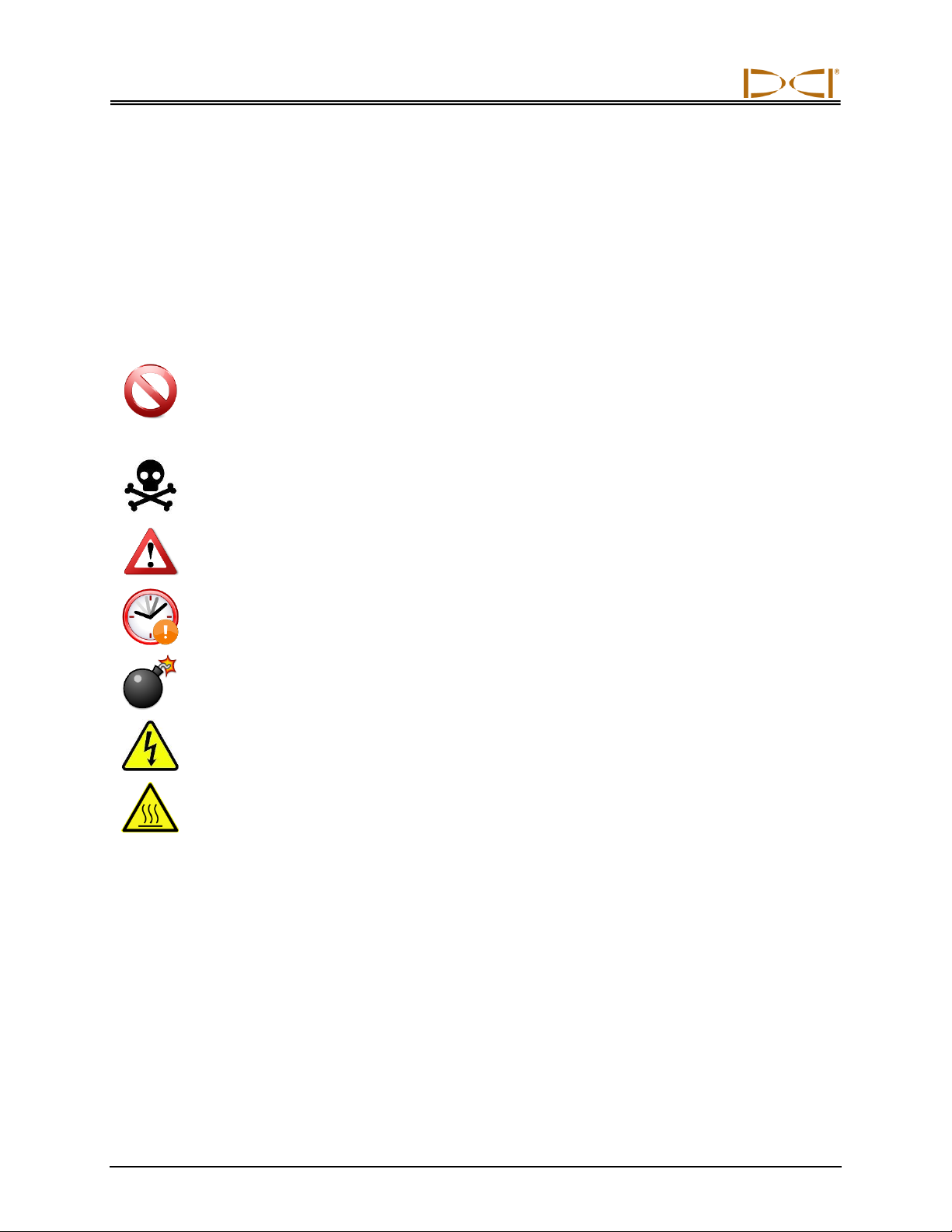
Warning All operators must read and understand the following safety
precautions and warnings and must review this operator’s manual
before using a DigiTrak Locating System.
Serious injury and death can result if underground drilling equipment makes
contact with an underground utility such as a high-voltage electrical cable or a
natural gas line.
Substantial property damage and liability can result if underground drilling
equipment makes contact with an underground utility such as a telephone, cable
TV, fiber-optic, water, or sewer line.
Work slowdowns and cost overruns can occur if drilling operators do not use the
drilling or locating equipment correctly to obtain proper performance.
DCI equipment is not explosion-proof and should never be used near flammable
or explosive substances.
In the event of electrostatic shock, the display screen may go blank. No data loss
will occur. Click the trigger to reset the receiver, or toggle down to reset the
remote display.
Hot surfaces can occur on cable transmitters if housing requirements are not met.
Always ensure the transmitter is installed properly in the housing during use.
Directional drilling operators MUST at all times:
Understand the safe and proper operation of drilling and locating equipment, including the use of
ground mats and proper grounding procedures.
Ensure that all underground utilities have been located, exposed, and accurately marked prior to
drilling.
Wear protective safety clothing such as dielectric boots, gloves, hard hats, high-visibility vests, and
safety glasses.
Locate and track the transmitter in the drill head accurately and correctly during drilling.
Maintain a minimum distance of 8 in. (20 cm) from the front of the receiver to the user’s torso to
ensure compliance with FCC requirements.
DIGITAL CONTROL INCORPORATED
DigiTrak®F5®SST®Operator’s Manual 7
Comply with federal, state, and local governmental regulations (such as OSHA).
Follow all other safety procedures.
DigiTrak locating systems cannot be used to locate utilities.
Continued exposure of the transmitter to heat due to frictional heating of the drill head can cause
inaccurate information to be displayed and may permanently damage the transmitter.
Remove the batteries from all system components during shipping and prolonged storage; damage
caused by leakage may occur.
Equipment and Battery Disposal
This symbol on equipment indicates that the equipment must not be disposed of with your
other household waste. Instead, it is your responsibility to dispose of such equipment at a
designated collection point for the recycling of batteries or electrical and electronic
equipment. If the equipment contains a banned substance, the label will show the pollutant
(Cd = Cadmium; Hg = Mercury; Pb = Lead) near this symbol. Before recycling, ensure
batteries are discharged or the terminals are covered with adhesive tape to prevent
shorting. The separate collection and recycling of your waste equipment at the time of
disposal will help conserve natural resources and ensure it is recycled in a manner that
protects human health and the environment. For more information about where you can
drop off your waste equipment for recycling, please contact your local city office, your
household waste disposal service, or the shop where you purchased the equipment.
The battery charger provided with your DigiTrak locating system is designed with adequate safeguards to
protect you from shock and other hazards when used as specified within this document. If you use the
battery charger in a manner not specified by this document, the protection provided may be impaired. Do
not attempt to disassemble the battery charger, it contains no user-serviceable parts. The battery charger
shall not be installed into caravans, recreational vehicles, or similar vehicles.
Pre-Drilling Testing
Before each drilling run, test your DigiTrak locating system with the transmitter inside the drill head to
confirm it is operating properly and providing accurate drill head location and heading information.
During drilling, the depth will not be accurate unless:
The receiver has been properly calibrated and the calibration has been checked for accuracy so the
receiver shows the correct depth.
The transmitter has been located correctly and accurately and the receiver is directly above the
transmitter in the drill head underground or at the front locate point.
The receiver is placed on the ground or held at the correct height-above-ground distance, which has
been set correctly.
Always test calibration after you have stopped drilling for any length of time.

DIGITAL CONTROL INCORPORATED
8 DigiTrak®F5®SST®Operator’s Manual
Interference
Interference can cause inaccuracies in the measurement of depth and loss of the transmitter’s pitch, roll,
or heading. Always perform a background n up to 6561 ft. (2000 m).oise check prior to drilling.
Sources of interference include, but are not limited to, traffic signal loops, invisible dog fences, cable
TV, power lines, fiber-trace lines, metal structures, cathodic protection, telephone lines, cell phones,
transmission towers, conductive earth, salt, salt water, rebar, and radio frequencies.
Interference at the remote display may also occur from other sources operating nearby on the same
frequency, such as car rental agencies using their remote check-in modules or other directional
drilling locating equipment.
Background noise must be minimal and signal strength must be at least 150 points above the
background noise during all locating operations.
Because this equipment may generate, use, and radiate radio frequency energy, there is no
guarantee that interference will not occur at a particular location. If this equipment does interfere with
radio or television reception, which can be determined by powering the equipment off and on, try to
correct the interference using one or more of the following measures:
oReorient or relocate the receiving antenna.
oIncrease the separation between the receiver and affected equipment.
oConsult the dealer, DCI, or an experienced radio/TV technician for help.
oConnect the DCI equipment to an outlet on a different circuit.

DIGITAL CONTROL INCORPORATED
DigiTrak®F5®SST®Operator’s Manual 9
Introduction
DigiTrak F5 SST Guidance System
The DigiTrak F5 SST Guidance System is designed for horizontal directional drilling (HDD) projects
where walkover locating is difficult. It provides real-time tool information that enables accurate steering of
the drill head directly from the remote display and computer interface. The SST (Short Steering Tool)
transmitter is a wireline device that has an internal compass to determine heading or direction. A
magnetic shield is provided for protection from magnetic fields when the transmitter is not in use, and a
special non-magnetic housing is required during drilling.
Steering data is shown in real time on both the remote display at the drill rig and on the laptop computer,
which can be placed up to 50 ft (15 m) away from the remote. The remote and computer are connected
through the cable box, which is also connected to the SST transmitter and the power source. The F5
receiver is used for calibration and to confirm transmitter data. DCI recommends that you use a
combination of walkover and non-walkover locating whenever possible to increase the capabilities and
accuracy of the SST system. A standard F5 system can be upgraded to the F5 SST system.
F5 SST transmitter
Magnetic
shield
Laptop computer
with LWD software
F5 SST
receiver
SST remote
display
Cable box
(MFCB)

Introduction
10 DigiTrak®F5®SST®Operator’s Manual
There are some important terms and procedures that are used specifically with the SST system that you
should understand. These include the following:
Heading –Azimuth compass heading or direction measured by the SST transmitter with respect
to the Earth’s North Pole. (Known as Yaw in the Eclipse steering tool system.)
Reference heading –Azimuth heading of the SST transmitter measured when it is accurately
positioned on the surveyed bore path prior to the start of the drill run. The course deviation is
determined from this heading. The value for the reference heading is determined at the start of
the SST operating procedure. (Known as reference yaw or Ref Yaw in the Eclipse steering tool
system.)
Shoot the probe –Term commonly used for the procedure of measuring the reference heading
using the SST transmitter (probe).
360° roll –Standard HDD walkover systems use a “clock” roll orientation. The SST transmitter
uses a 360° roll sensor with 1° increments, where 0° = 12 o’clock, 90° = 3 o’clock, 180° =
6 o’clock, and 270° = 9 o’clock.
The following types of data are displayed and recorded with the SST guidance system:
Heading (in tenths of a degree) –Displayed on receiver and remote and recorded on computer.
Reference heading (in tenths of a degree) –Displayed on remote and recorded on computer.
Heading deviation (in tenths of a degree) –Amount of deviation SST transmitter is exhibiting from
the reference heading; displayed on remote and recorded on computer.
Depth (in feet or meters), pitch (in tenths of a percent or tenths of a degree), and roll (in degrees
from 0–360°) –Displayed on receiver and remote when receiver is used for walkover locating;
calculated depth is displayed and recorded on computer.
Course deviation (in feet/meters) –Displayed and recorded on computer.
Temperature (in degrees Fahrenheit or Celsius) –Displayed on receiver and remote; not
recorded on computer.
Voltage levels for power supply and SST transmitter (in volts) –Displayed on remote; not
recorded on computer.
System current (in amps) –Displayed on remote; not recorded on computer.
Distance from drill rig and bore distance (in feet/meters) –Displayed and recorded on computer
only.
Date and time of recording –Displayed and recorded on computer only.
To further expedite wireline connection time, the SST system can be used with the DigiTrak CableLink
connection system. The CableLink system is preinstalled in drill rods so that the electrical connection is
made when the rods are threaded up.
This operator’s manual begins by describing the primary System Components—including the SST
transmitter, the F5 SST receiver, the SST remote display, the multi-function cable box (MFCB), and the
laptop computer with preinstalled LWD (Log-While-Drilling) software—and the other supplies needed for

Introduction
DigiTrak®F5®SST®Operator’s Manual 11
using the SST system. The next section presents the System Operating Instructions, which cover the
standard procedure for setting up and using the SST guidance system. This is followed by instructions for
using the LWD computer software in general (LWD Software Instructions), and then by detailed
information on Inputting and Editing Drill Data in the computer. System specifications and maintenance
requirements are provided in Appendix A, and specific instructions for repair of the wireline components
in the SST transmitter are given in Appendix B.
Some terms and techniques used in this manual are considered basic to the F5 locating system. If you
have never used the F5 system, then you are required to read the operator’s manual for the system
(DigiTrak F5 Directional Drilling Locating System Operator’s Manual) before using the SST system.
NOTE: You must know how to operate the F5 locating system prior to operating the F5
SST guidance system.
You also must read the instructions given in this SST system operator’s manual and familiarize yourself
with the various menu screens on your F5 SST receiver and remote display before using the system for a
production drill. We also recommend that you review the LWD software application and the help files in
the software relating to the SST (steering tool) guidance system. If you have questions, please call DCI
Customer Service.
DIGITAL CONTROL INCORPORATED
DigiTrak®F5®SST®Operator’s Manual 12
System Components
The F5 SST guidance system consists of the following main components, which are described in this
section:
SST transmitter –A cable transmitter with an internal compass; requires protective magnetic
shield.
F5 SST receiver –An F5 receiver upgraded with the SST capability.
SST remote display –A multi-function remote display (DigiTrak FSD or MFD) with SST capability.
Multi-function cable box (MFCB) –An interface unit that connects all hard-wired system com-
ponents, including the SST transmitter, remote display, computer, and power source.
Laptop computer with LWD software –A dedicated computer with LWD software preinstalled and
ready to use.
In addition, some equipment, tooling, and specialty items are required for use with the SST system but
are not provided by DCI. These items are identified and described at the end of this section.
SST Transmitter with Magnetic Shield
The SST transmitter is similar to the standard cable transmitter except that it also provides heading
information and requires special non-magnetic shielding and a non-magnetic housing. The heading
information, in addition to the pitch and roll data, enables the drill operator to determine the SST
transmitter’s position and orientation, and thus allows steering of the tool.
The SST transmitter provides heading and pitch updates every 1.3 seconds and roll updates more than 3
times per second. The SST transmitter has a repairable end cap assembly; two spare assemblies are
provided with the transmitter so that the cable lead and end cap components can be replaced or rebuilt as
needed (see Appendix B).
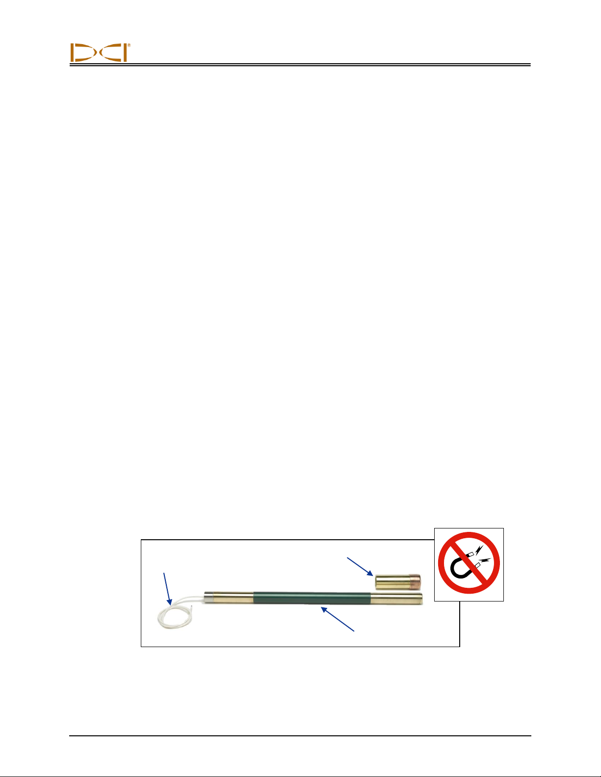
Because the SST transmitter is a magnetic-sensitive device, it needs to be kept away from all magnetic
sources. A protective magnetic shield, which is essentially a copper sleeve, is provided with the SST
transmitter. The magnetic shield should be placed on the end of the SST transmitter at all times when the
transmitter is not in use.
SST Transmitter and Protective Magnetic Shield
White wire
to cable box
Magnetic shield
SST transmitter

System Components
DigiTrak®F5®SST®Operator’s Manual 13
NOTE: The SST transmitter must be kept at least 5 ft (1.5 m) away from all magnets including the
remote display, which has a magnetic mount that will damage the transmitter. A special non-
magnetic housing is required.
The non-magnetic housing for the SST transmitter must be a rear-load housing. To prevent overheating
and for optimum performance, the transmitter must be installed correctly in the housing. An extraction/-
insertion tool is provided with the SST transmitter for use in properly installing it into and removing it from
the housing. Installation instructions are provided in the System Operating Instructions section.
It is critical that the slots in the drill housing meet minimum length and width requirements and be
correctly positioned. DCI recommends at least three slots equally spaced around the circumference of the
housing. Each slot must be at least 1/16 or 0.0625 in. (1.6 mm) wide. For accuracy, slot measurements
must be taken from the inside of the housing. The SST transmitter, which is 24 in. (60.96 cm) long,
requires slots in the housing that are at least 9 in. (22.9 cm) long and begin at least 8.5 in. (21.6 cm) from
the front end of the transmitter, as shown below.
SST Transmitter Housing Slot Requirements
F5 SST Receiver
The F5 SST receiver is an F5 receiver that has been upgraded with the SST capability. The receiver is
used to locate the SST transmitter when walkover locating is possible and to confirm depth readings and
other transmitter data. The locating procedure for the SST is the same as that for the standard F5 locating
system, with simple two-button (trigger and toggle switch) operation.
F5 SST Receiver Side View (left) and Top View (right)
Display
screen
Trigger
switch
Toggle switch
Slot position
8.5 in.
(21.6 cm)
Slot length
9 in. (22.9 cm)
Front end
Wireline end
System Components
14 DigiTrak®F5®SST®Operator’s Manual
Any F5 receiver can be upgraded to have the SST capability. The SST upgrade adds the SST option, as
defined below, to the cable transmitter menu.
SST transmitter option –Enables detection of an SST transmitter when the SST receiver
is in locate mode. This transmitter option must be selected to calibrate and track the SST
transmitter using the receiver. When an SST transmitter is selected, the SST heading
information appears on the locate mode screen and the roll indicator on the receiver
display shows units in degrees (from 0° to 360°) rather than the standard clock positions.
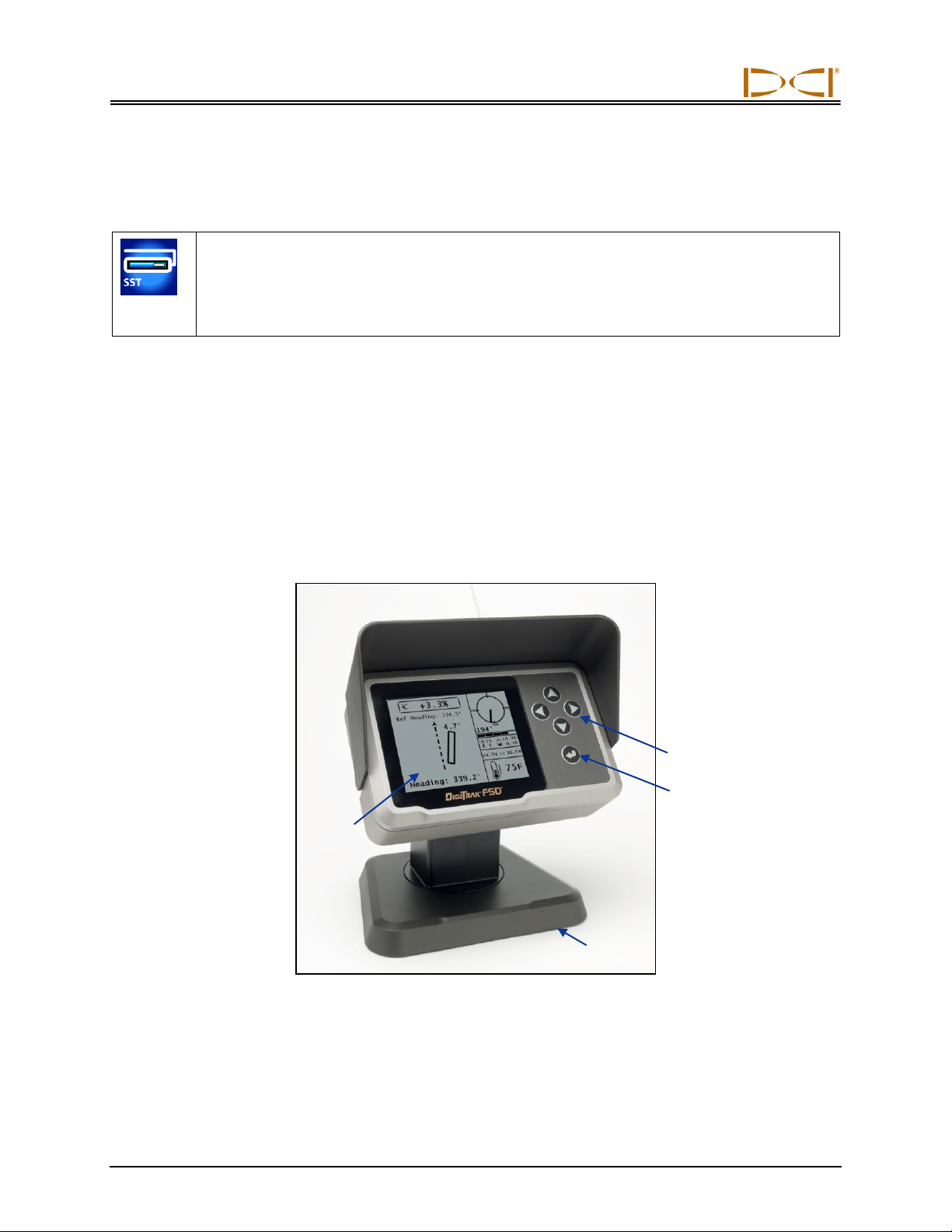
SST Remote Display
The SST remote display is a multi-function remote that receives and displays real-time information
including heading, pitch, roll, temperature, and battery status. Any DigiTrak F Series Display (FSD) or
DigiTrak Multi-Function Display (MFD) can be upgraded to have the SST capability.
An SST remote operates much like a standard remote display, with the function buttons on the keypad
(direction buttons and execute button) and the main menus operating in the same manner. The SST
remote menu options include the standard options plus an option to set the reference heading. This menu
option is discussed further in the System Operating Instructions section.
SST Remote Display
An SST remote operating in cable mode with an SST transmitter will show roll units in degrees (from 0° to
360°), whereas a standard remote display operating with other transmitters shows roll units that cor-
respond to the numbers on a clock (1 through 12).
Display
screen
Direction
buttons
Execute
button
Magnetic
base
System Components
DigiTrak®F5®SST®Operator’s Manual 15
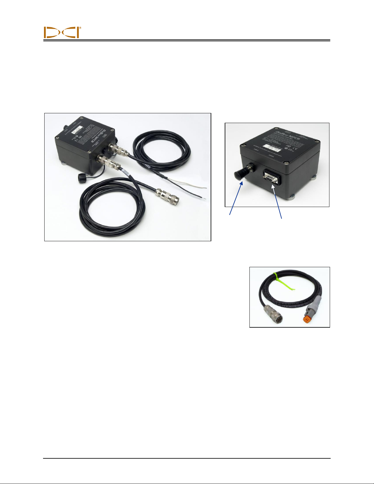
Multi-Function Cable Box (MFCB)
The cable box routes power to the SST transmitter and the remote display and sends transmitter data to
the remote and the computer laptop. It is installed between the DC power port on the back of the remote
display and a DC power source.
Cable Box with Power Supply and Remote Display Cables
A special power cable is provided for use with a panel-mounted MFD
remote. This cable plugs into the back of the MFD and the other end
connects to the cable box.
The white wire from the SST transmitter connects to the power post on
the cable box. The laptop computer is connected to the serial port on
the cable box. When connected, real-time data can be viewed at the
computer, and data points can be logged by the computer operator. The
SST software allows for viewing, logging, editing, graphing, saving, and
printing of the drill data. See the LWD Software Instructions section for
more information.
Complete information and procedures for setting up the SST system
and connecting the system components is given in the System Oper-
ating Instructions section.
Cable to
power supply
Cable to
remote display
Power post for
SST wireline
Serial port for
computer connection
Cable for Panel-Mounted
MFD Remote
System Components
16 DigiTrak®F5®SST®Operator’s Manual
Laptop Computer with LWD Software
The F5 SST system comes with a dedicated laptop computer (PC) that has the LWD (Log-While-Drilling)
software preinstalled. A 50-ft (15-m) long serial cable is provided for connecting the computer to the serial
port on the cable box. A USB flash drive that contains the LWD software, this operator’s manual, and
sample data is also provided with the system.
The LWD software is used with other LWD applications; however, only the information that is pertinent to
running the SST guidance system is included in this manual. Instructions for the other LWD applications
are given in the DigiTrak LWD DataLog System Operator’s Manual.
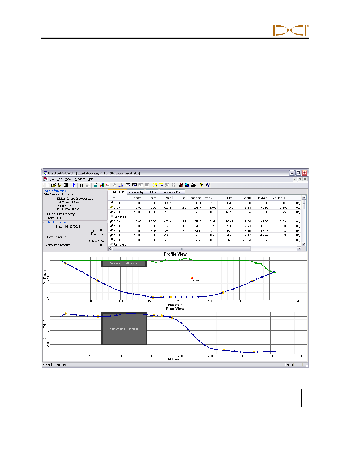
The steering application in the LWD software is used with the SST system. A typical steering job screen
as it appears in the LWD application window is shown below. See the LWD Software Instructions and the
Inputting and Editing Drill Data sections in this manual for more information about the software and how
to use it.
LWD Steering Tool Application Window
NOTE: Loading additional programs on the dedicated SST laptop could cause problems with
the functioning of the LWD software.

System Components
DigiTrak®F5®SST®Operator’s Manual 17
Non-DCI Components That Are Needed
Some equipment, tooling, and specialty items required for operation of the SST system are not supplied
by DCI. These include the following:
Non-magnetic housing for SST transmitter –Must be rear-loading with slots milled per the
housing slot requirements discussed earlier in this section.
Monel (non-magnetic drill rod) –A monel approximately 15-ft (4.6-m) long for use between the
non-magnetic housing and the first drill rod; a second monel may be required if you are using a
mud motor.
Fish tape or device to fish wire through rod
10-gauge wire –Approximately 20 ft (6 m) for use as a ground connection when establishing the
reference heading.
10-gauge wire –Enough for bore length and additional for pullback of rods.
Butt splices for 10/12 gauge wire
Heat shrinks
Crimper
Heat gun
Transit or theodolite
String for string line
Tape measure
12–28V DC battery or power supply
Amp meter
Digital level
Compression fitting –Required to seal the transmitter from drilling fluid; contact a drill or tooling
manufacturer for information.

DIGITAL CONTROL INCORPORATED
DigiTrak®F5®SST®Operator’s Manual 18
System Operating Instructions
The SST guidance system provides information at the remote display and the computer that enables you
to make accurate, reliable steering decisions. It also allows you to log and save the drill data.
This section provides detailed operating instructions for using the system. Please read the procedure
carefully and ensure that you understand all the instructions before you use the system. Also, before you
start to set up the system, be sure you have all the non-DCI components that you will need, as specified
in the System Components section under “Non-DCI Components That Are Needed.”
The basic operating procedure includes the following general steps, which are detailed in this section:
Setting Up SST Laptop
Setting Up Equipment and Site
Setting Reference Heading and Roll Offset
Calibrating SST Transmitter and Confirming Proper System Operation
Logging Drill Run
A summary of the procedure is provided at the end of the section.
Setting Up SST Laptop
1. Plot Topography, Drill Plan, and Planned Deviation
Any topographic and/or planned bore information that you want in your SST job file can be input into the
SST software before drilling or during the drilling/logging process. DCI recommends that you input this
information before drilling unless you have a dedicated computer operator who can ensure correct and
accurate input. Instructions for inputting data are provided in the Inputting and Editing Drill Data section.
Setting Up Equipment and Site
2. Establish Bore Path Reference Line and Mark Bore Path
We recommend that you use surveying equipment to establish the bore path. Once, established, mark
the bore path with a string line based off of the survey markers. This reference line will help in aligning the
drill and non-mag tooling assembly to the intended bore path.
3. Assemble and Torque-up Non-Magnetic Housing to Non-Mag Tool
Using the drill rig or other hydraulic torquing wrenches, thread the non-mag housing to the non-mag tool
and torque-up.

Operating Instructions
DigiTrak®F5®SST®Operator’s Manual 19
4. Align Drill to Marked Bore Path
With the transit positioned at least 10 ft (3 m) ahead of the drill, position the drill so that the transit sights
onto the center point of the drive chuck and/or centerline of the boom. Anchor the drill, and then use the
transit to confirm that the drill is still aligned to the marked bore path; if not, adjust for proper alignment.
Aligning Drill to Marked Bore Path
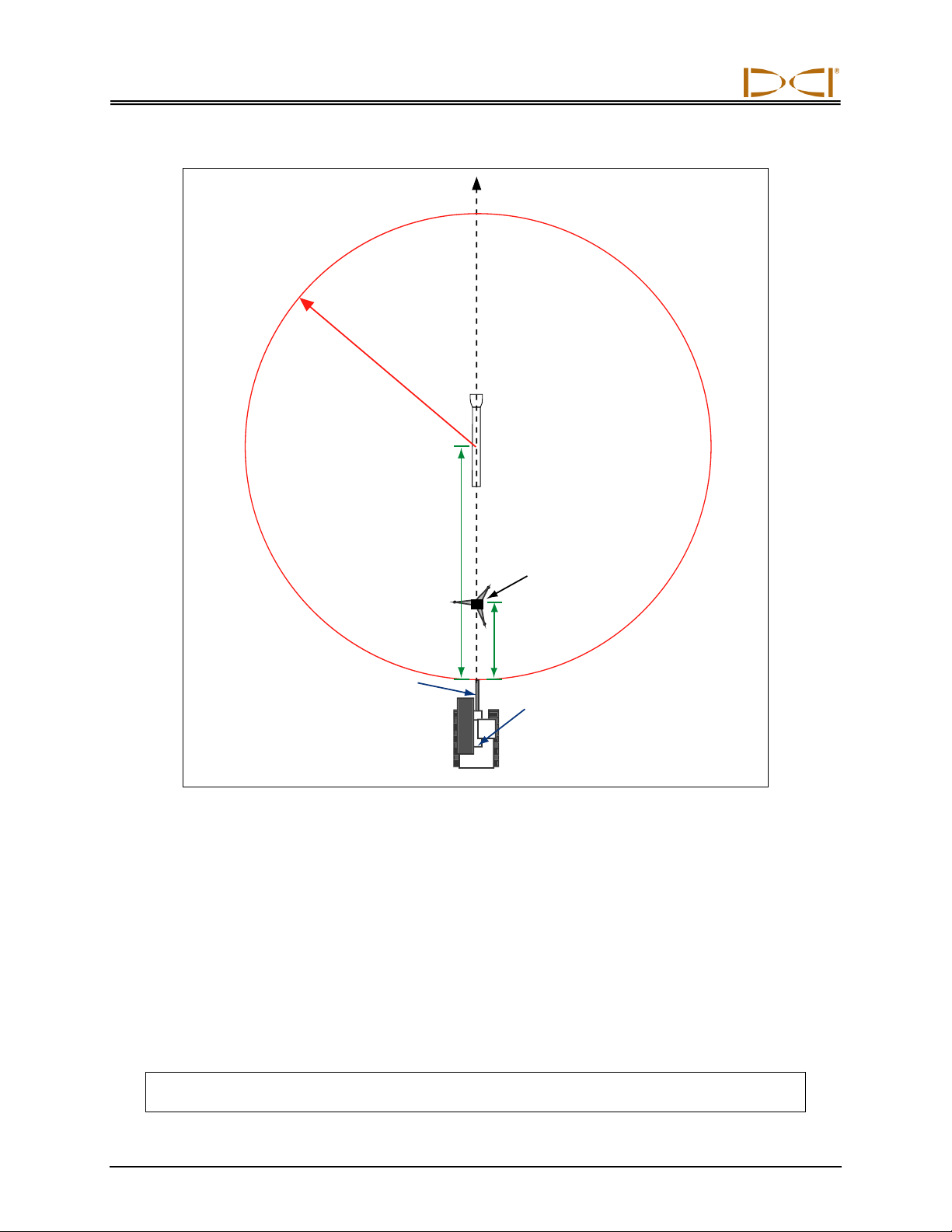
5. Position & Align Non-mag
Tooling Assembly onto
Marked Bore Path
With the transit still in position but rotated 180°,
place the tooling assembly at least 30 ft (9 m) in
front of the drill, onto the marked bore path so that it
is pointing in the direction of drilling with the tool or
bent sub oriented to 0° (12 o’clock), as shown in the
photo on the right and the SST Job Site Setup
diagram below. Sight the transit onto the string line
(highlighted by yellow dashed line in photo) and
carefully align the non-mag assembly to the marked
bore path.
Be sure there are no large metallic objects, in-
cluding the drill, within 30 ft (9 m) of the non-mag
assembly.
Aligning Non-Mag Tooling
Assembly to Marked Bore Path
Operating Instructions
20 DigiTrak®F5®SST®Operator’s Manual
SST Job Site Setup
6. Stage SST Equipment and Power Source Adjacent to Tooling Assembly
In preparation for powering up the F5 SST equipment, position the following items adjacent to the tooling
assembly, along with the required cords, cables, and supplies for connecting the components:
F5 SST receiver and fully charged battery pack
SST transmitter
SST remote display (if using a panel-mounted MFD, remove it from the drill rig console; contact
your dealer for assistance if necessary)
Multi-function cable box (MFCB)
Power source, such as a generator or 12–28V battery
Amp meter
NOTE: Keep the remote display with its magnetic mounting bracket at least 5 ft (1.5 m) from
the SST transmitter or damage to the SST transmitter could occur.
At least 30 ft (9 m)
from tool to drill
About 10 ft (3 m)
from transit
to drill
MINIMUM
30 ft (9 m)
NO METAL ZONE
Surveyed
bore path
marked with
string line
Non-mag tooling
assembly with
bit oriented at 0°
Transit
Centerline of boom
Centerpoint of drive chuck
Drill
Table of contents
Popular Industrial Equipment manuals by other brands


Siemens
Siemens SIMOGEAR BA 2030 Translation of the original operating instructions

AVK
AVK 601 Series Installation, operation & maintenance manual

Graco
Graco Reactor E-20 Series manual

Pfannenberg
Pfannenberg PWS 7 Series Operating and installation instructions

Schaeffler
Schaeffler VarioSense user manual

Jäger
Jäger C80-M440.01 S15 manual


