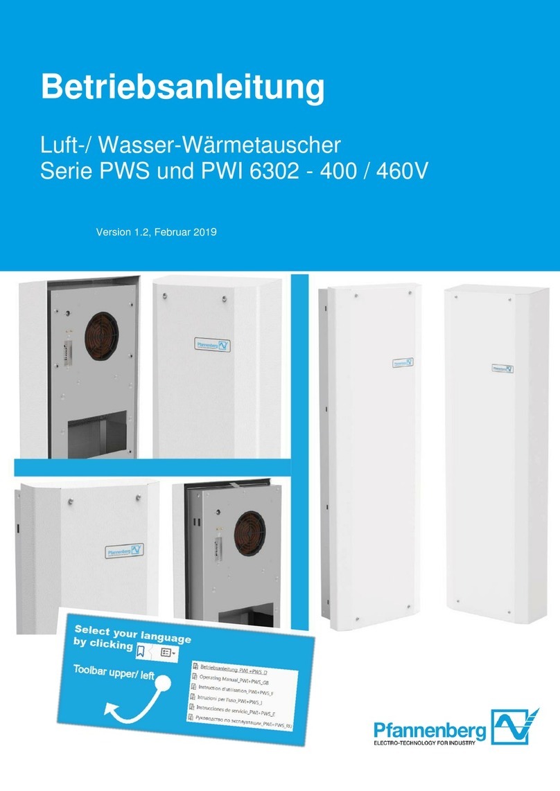
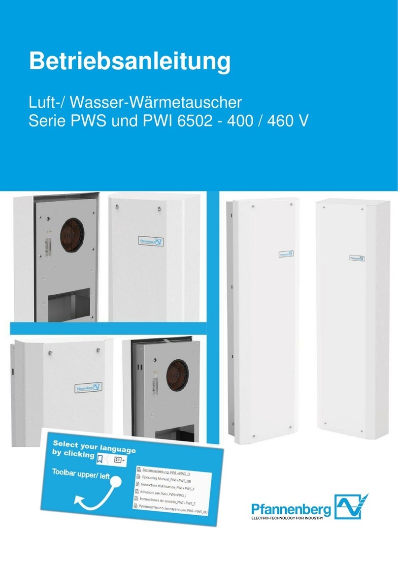
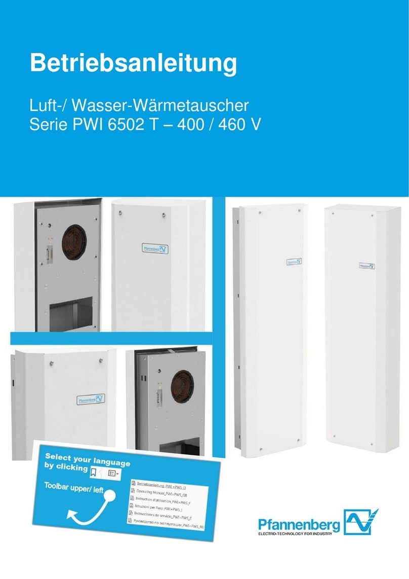
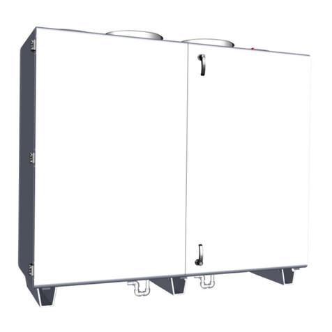
Pfannenberg PWS 7 Series User manual

Stand 09.97
Betriebs- und Montageanleitung
Operating- and installation
instructions
Notice de montage et d'utilisation
PWD 5302
PWD 5402
PWS 7 . . .

Pfannenberg
209.97
Inhalt / Contents / Sommaire
1Deutsch
1.1 Auspacken und Handhabung ..................................................................................4
1.2 Allgemeine Angaben...............................................................................................4
1.3 Typschild und technische Daten..............................................................................4
1.4 Anwendung und Funktion........................................................................................5
1.5 Montageanleitung...................................................................................................6
1.5.1 Gehäusemontage ...................................................................................................6
1.5.2 Elektrischer Anschluß.............................................................................................6
1.5.3 Hydraulischer Anschluß..........................................................................................7
1.6 Inbetriebnahme und Bedienung ..............................................................................7
1.7 Optionen.................................................................................................................7
1.7.1 Thermostat und Magnetventil .................................................................................7
1.7.2 Thermischer Wassermengenregler.........................................................................8
1.7.3 Wassermengenventil..............................................................................................8
1.7.4 Geräte mit Typenendziffer ..12 ...............................................................................8
1.8 Was tun wenn ........................................................................................................9
1.9 Wartung..................................................................................................................10
1.10 Außerbetriebnahme................................................................................................10
1.11 Gewährleistungsbestimmungen..............................................................................10
2English
2.1 Unpacking and handling..........................................................................................11
2.2 General information................................................................................................11
2.3 Technical data and ID plate ....................................................................................11
2.4 Application and function..........................................................................................12
2.5 Installation instructions............................................................................................13
2.5.1 Mounting the housing..............................................................................................13
2.5.2 Electrical connection...............................................................................................13
2.5.3 Connection to water supply system.........................................................................14
2.6 Start-up and operation............................................................................................14
2.7 Optional items ........................................................................................................14
2.7.1 Thermostat and solenoid valve...............................................................................14
2.7.2 Thermostatic water-capacity controller....................................................................15
2.7.3 Water-capacity valve..............................................................................................15
2.7.4 Unit model designations ending in ..12....................................................................15
2.8 Troubleshooting: What to do if ...............................................................................16
2.9 Maintenance...........................................................................................................17
2.10 Shutdown................................................................................................................17
2.11 Guarantee conditions..............................................................................................17

Pfannenberg
09.97 3
3Français
3.1 Déballage et manipulation ......................................................................................18
3.2 Indications générales..............................................................................................18
3.3 Plaquette signalétique et caractéristiques techniques..............................................18
3.4 Application et fonction ............................................................................................19
3.5 Instruction de montage ...........................................................................................20
3.5.1 Montage du boîtier..................................................................................................20
3.5.2 Branchement électrique..........................................................................................20
3.5.3 Branchement hydraulique.......................................................................................21
3.6 Mise en service et commande ................................................................................21
3.7 Options...................................................................................................................21
3.7.1 Thermostat et électrovanne....................................................................................21
3.7.2 Régulateur de quantité d'eau thermique..................................................................22
3.7.3 Soupape de quantité d'eau .....................................................................................22
3.7.4 Appareils avec chiffre terminal de type ..12 ............................................................22
3.8 Que faire si ............................................................................................................23
3.9 Maintenance...........................................................................................................24
3.10 Mise hors service....................................................................................................24
3.11 Dispositions concernant la garantie.........................................................................24
Anlage / Annex / Appendices
Technische Daten Luft-/Wasser-Wärmeaustauscher ........................................................26
Technical data for air-to-water heat exchanger.................................................................26
Caractéristiques techniques de l'échangeur de chaleur air/eau .........................................26
Schaltplan PWD-/PWS-Geräte.........................................................................................28
Circuit diagram for PWD/PWS .........................................................................................28
Schéma électrique des PWD/PWS...................................................................................28
Chemische Anforderungen an die Qualität von Kreislaufkühlwasser für kleine und
mittlere offene Rückkühlsysteme......................................................................................29
Chemical requirements for circulating cooling water in small and medium-sized
open recooling systems....................................................................................................29
Exigences chimiques à la qualité de l'eau de refroidissement du circuit pour les
systèmes de refroidissement de retour ouverts petits et moyens.......................................29
Kv-Werte des thermischen Wassermengenreglers ...........................................................31
Kv-values for the thermostatic water-capacity controller...................................................31
Valeurs Kv du régulateur de quantité d'eau thermique......................................................31
Ersatzteilliste/ Spare part list/ Liste de pièces de rechange...............................................32
Vertretungen.....................................................................................................................33

Pfannenberg
409.97
1. Deutsch
1.1. Auspacken und Handhabung
Vor und beim Auspacken des Wärmeaustauschers muß eine Sichtkontrolle
durchgeführt werden, um eventuelle Transportschäden festzustellen. Bitte
achten Sie auf lose Teile, Beulen, Kratzer, etc.
Eventuelle Schäden sind sofort dem Transportunternehmen zu melden
("Bestimmungen für Schadensfälle" beachten). Im übrigen gelten die
"Allgemeinen Bedingungen für Lieferungen und Leistungen" des ZVEI
(Zentralverband der Elektrotechnischen Industrie) in der jeweils neuesten
Fassung.
Vor Entsorgung des Verpackungsmaterials dieses bitte auf lose Funktionsteile
kontrollieren.
Zur Bearbeitung von Gewährleistungsansprüchen bitten wir um genaue
Angaben des Mangels (evtl. Foto) sowie um Angabe der Typbezeichnung und
Seriennummer des Gerätes.
1.2. Allgemeine Angaben
Im Falle eines Transportes der Schaltanlage empfehlen wir den
Wärmeaustauscher abzubauen und getrennt verpackt zum Versand zu
bringen. Beim Handling das Gerät bitte nur am Gehäuse oder am
Geräterahmen fassen.
Alle Pfannenberg-Geräte sind frei von Silikonverbindungen, PCB, PCT,
Asbest, Formaldehyd, Cadmium und benetzungsstörenden Substanzen.
Bei der Konstruktion der Geräte wurden EN 292, EN 294, und EN 60335
berücksichtigt.
Alle Geräte werden im Werk auf Dichtheit geprüft.
Im Inneren des Gerätes befindet sich nützliches Zubehör, das Sie vor
Inbetriebnahme des Gerätes herausnehmen müssen. Bitte beachten Sie hierzu
die Montageanleitung.
1.3. Typschild und technische Daten
Für die Installation und Wartung sind die Angaben auf dem Typschild zu
beachten. Es befindet sich an der rechten Seite des Gerätes.
Eine Übersicht der technischen Daten finden Sie im Anhang.

Pfannenberg
09.97 5
1.4. Anwendung und Funktion
Die Luft-/Wasser-Wärmeaustauscher der Baureihe PWD und PWS sind
Kompaktgeräte, die nur noch an die zu kühlende Anlageneinheit montiert und
elektrisch und hydraulisch angeschlossen werden müssen. Danach können die
Geräte sofort in Betrieb genommen werden. Die Geräte wurden für die
Wärmeableitung aus dichten Schaltschränken und -gehäusen konzipiert.
Eine andere oder darüber hinausgehende Nutzung gilt als nicht
bestimmungsgemäß.
Nach Anlegen der Betriebsspannung beginnt der Lüfter sofort zu arbeiten. Die
Luft wird dabei aus dem Schaltschrank/-gehäuse abgesaugt und über den
Wärmeaustauscher wieder in den Schaltschrank zurückgeführt. Die erhitzte
Luft wird am Wärmeaustauscher abgekühlt und je nach Betriebszustand
eventuell auch entfeuchtet. Die der Luft entzogene Wärme wird über den
Wasserkreislauf (Glykolkreislauf) einem externen Kühlsystem zugeführt.
Die Kühlfunktion eines Luft-/Wasser-Wärmeaustauschers ist nur dann
gewährleistet, wenn die für die Kühlung benötigte Flüssigkeit im Vorlauf
mindestens 10 K kälter ist als die Lufteintrittstemperatur in den
Wärmeaustauscher (Temperaturdifferenz unter Nennbedingungen = 15 K).
Werden die Geräte außerhalb der zugelassenen Umgebungstemperaturen
betrieben, reduziert sich die Lebensdauer der Ventilatoren in Abhängigkeit von
deren Betriebstemperatur. Bei Dauertemperaturen über 55°C muß mit dem
Ausfall der Motoren gerechnet werden!
ACHTUNG:
Bei jeder wirksamen Kühlung kann Kondenswasser anfallen. Das Gerät
sollte deshalb nur an dichten Schränken und Gehäusen eingesetzt und
betrieben werden.
Die Installation eines Türkontaktschalters zum Abschalten des Gerätes beim
Öffnen der Schaltschranktür wird empfohlen.
Geräte in der Standardausführung haben keine regelungstechnischen
Einrichtungen. Eine eventuell erforderliche Temperaturregelung erfolgt extern
durch eine Anpassung des Flüssigkeitsmassenstromes oder der
Vorlauftemperatur.
Pfannenberg bietet Ihnen jedoch auch Geräte mit Optionen für eine optimale
Temperaturregelung im Schaltschrank an. Beachten Sie bitte dazu die
Optionen dieser Anleitung oder lassen Sie sich von unserem Verkaufspersonal
beraten.

Pfannenberg
609.97
1.5. Montageanleitung
1.5.1. Gehäusemontage
•Gerät waagerecht hinlegen. Befestigungsschrauben an der Frontseite um
ca. 180° nach links drehen. Haube nach oben abziehen.
•Beipack entnehmen. (Befestigungsschrauben, Kantenschutz, Schlauchan-
schluß, Bohrschablone)
•Bohrschablone auf die Außenseite der Befestigungsfläche des
Schaltschrankes legen. Löcher bohren und Luftdurchlaßöffnungen
herausschneiden.
Achtung: Verhindern Sie daß Späne in den Schaltschrank gelangen.
•Profildichtung in die Ausschnitte einlegen. Die Dichtung dient gleichzeitig als
Kantenschutz und als luftseitige Abdichtung zwischen Umgebung und
Schaltschrank. Dichtungen so einlegen, daß die Stoßenden seitlich liegen.
Nur wenn die Dichtung einwandfrei verlegt ist, bleibt die Schutzart des
Schaltschrankes erhalten.
•Wärmeaustauscher mittels der im Beipack befindlichen Schrauben von der
Schaltschrankinnenseite her befestigen.
•Wasser- und Elektroanschluß vornehmen. Danach Haube wieder aufsetzen.
Dabei Erdungskabel auf den Erdungsstecker in der Haube stecken!
Die freie Zirkulation der Kühlluft zum Wärmeaustauscher muß zu jeder Zeit
über den vollen freien Belüftungsquerschnitt gewährleistet sein.
Wichtig ist, daß an den Zu- und Rückluftöffnungen die Flächendichtungen
richtig angeordnet sind und vom Gerät gepreßt werden, so daß keine
Umgebungsluft in den inneren Luftkreislauf gesaugt werden kann.
Der Kondesatablauf aus dem Gerät muß direkt mit Gefälle nach unten
erfolgen. Es kann ein Schlauch mit Innendurchmesser 12 mm verwendet
werden, der knickfrei verlegt sein muß. Den Schlauch bitte mit einer
Schlauchschelle sichern.
1.5.2. Elektrischer Anschluß
Der elektrische Anschluß erfolgt über die Kabelverschraubung an der linken
Unterseite des Gerätes. Netzanschlußkabel am Wärmeaustauscherpaket
vorbei durch den Isolierstreifen zu den Klemmen auf der Lüftertraverse führen
und gemäß Schaltplan anschließen. Den Isolierstreifen dabei nicht entfernen.
Absicherung entsprechend der Stromaufnahme des Gerätes vorsehen (siehe
technische Daten am Typschild).
ACHTUNG:
Netzspannung und Netzfrequenz müssen mit den am Typschild des
Gerätes angegebenen Nennwerten übereinstimmen.
Arbeiten an elektrischen Systemen dürfen nur von Sachkundigen
durchgeführt werden. Die einschlägigen örtlichen Sicherheitsvorschriften
sind zu beachten.
Alle Geräte werden im Werk nach EN 60335 einer elektrischen
Sicherheitsprüfung unterzogen. Damit entfällt nach UVV-VBG 4, §5 (4) die
Verpflichtung des Betreibers, vor der ersten Inbetriebnahme der elektrischen
Anlage diese zu überprüfen.

Pfannenberg
09.97 7
1.5.3. Hydraulischer Anschluß
Am einfachsten ist ein Schlauchanschluß. Dafür befinden sich im Beipack 2
Schlauchtüllen mit Überwurfmutter (SW24). Beim Anziehen der Schlauchtüllen
bitte mit einem 2. Schraubenschlüssel (SW 24) gegenhalten.
Wir empfehlen nur druckbeständige (>10 bar) Schläuche mit einem freien
Mindestdurchmesser von 12 mm (altern. 1/2"). Eingefärbte Materialien sind
günstiger als Klarsichtmaterial. Bei letzterem kann durch Sonnen- und
Lichteinwirkung Algenbildung entstehen.
Beim Anschluß dürfen Vor- und Rücklauf (Wasserein- und -austritt) nicht
verwechselt werden.
Hinweisschilder am Gerät beachten !!!
1.6. Inbetriebnahme und Bedienung
Nach erfolgter Montage und elektrischem Anschluß kann der Wärmeaus-
tauscher sofort in Betrieb genommen werden.
ACHTUNG:
Bei Anlegen der Betriebsspannung beginnt der Ventilator sofort zu
drehen.
Bei den Standardgeräten ist keine weitere Bedienung mehr erforderlich.
1.7. Optionen
1.7.1. Thermostat und Magnetventil
Auf Wunsch können Ihnen die Geräte mit integriertem mechanischem
Thermostat und Magnetventil geliefert werden. Der Thermostatfühler erfaßt die
Rücklufttemperatur und steuert entsprechend der Temperatureinstellung das
Magnetventil an. Bei steigender Temperatur der Rückluft aus dem
Schaltschrank öffnet das Magnetventil und Kühlflüssigkeit durchströmt den
Wärmeaustauscher.
Das Magnetventil ist im Rücklauf angeordnet, damit bei "offenen
Kühlkreisläufen" der Wärmeaustauscher nicht leer läuft und sich Luftblasen im
System bilden.
Die Einstellung der Solltemperatur erfolgt am Thermostat. Dieser ist auf der
Lüfterkonsole angeordnet. Wir empfehlen die Solltemperatur ca. 10-15 K über
der Vorlauftemperatur der Kühlflüssigkeit einzustellen.
Die Werkseinstellung ist 35°C.
Achtung:
Vor Abnehmen der Haube das Gerät spannungsfrei schalten und warten
bis der Ventilator zum Stillstand gekommen ist. Verletzungsgefahr !
Bei Geräten mit ABL-Steckanschluß ist im Beipack das zugehörige
Netzanschlußkabel enthalten.

Pfannenberg
809.97
1.7.2. Thermischer Wassermengenregler
Auf Wunsch können die Geräte mit integriertem thermostatisch geregeltem
Wassermengenregler geliefert werden. Der Thermostatfühler erfaßt die
Rücklufttemperatur aus dem Schaltschrank und steuert entsprechend der
Temperatureinstellung das Regelventil an. Der Thermostatregler ist ein
Proportionalregler ohne Hilfsenergie.
Der Sollwertbereich kann bei Nenndurchfluß zwischen 20°C und 70°C
eingestellt werden.
Den max. Differenzdruck entnehmen Sie bitte der technischen Datentabelle im
Anhang. Die Kenndaten des Ventils und die KV-Werte finden Sie in der Anlage.
Das Regelventil ist im Rücklauf angeordnet, damit bei "offenen
Kühlkreisläufen" der Wärmeaustauscher nicht leer läuft und sich Luftblasen im
System bilden.
Die Einstellung der Solltemperatur erfolgt am Thermostatkopf auf dem
Ventilkörper. Wir empfehlen die Solltemperatur ca. 10-15 K über der
Vorlauftemperatur der Kühlflüssigkeit einzustellen.
Die Werkseinstellung ist ca. 35°C.
Achtung:
Vor Abnehmen der Haube das Gerät spannungsfrei schalten und warten
bis der Ventilator zum Stillstand gekommen ist. Verletzungsgefahr !
1.7.3. Wassermengenventil
Auf Wunsch können die Geräte mit einem integrierten Wasserventil geliefert
werden. Das Ventil kann nach Abnahme der Schutzhaube mit Hilfe eines
Sechskant-Stiftschlüssels (Inbusschlüssel S6) verstellt werden. Dadurch ist es
möglich den Volumenstrom des Kühlmediums zu verändern und damit die
Nennleistung des Gerätes zu drosseln.
Werkseinstellung ist der maximale Durchfluß.
Auf Wunsch kann zusätzlich noch ein Thermostat auf der Lüfterkonsole
montiert werden. Damit kann ein externer Schaltvorgang oder ein Warnsignal
herausgegeben werden.
Achtung:
Vor Abnehmen der Haube das Gerät spannungsfrei schalten und warten
bis der Ventilator zum Stillstand gekommen ist. Verletzungsgefahr !
1.7.4. Geräte mit Typenendziffer ..12
Die Befestigung dieser Geräte erfolgt von der Innenseite mit Hilfe von M6
Schrauben (siehe Beipack) die durch die Rückwand gesteckt werden.
Zusätzlich ist bei diesen Geräten die Drehzahl und damit der Luftvolumenstrom
durch einen Vorschaltwiderstand in der Zuleitung zum Ventilator gedrosselt.

Pfannenberg
09.97 9
1.8. Was tun wenn ...
... trotz aller Sorgfalt einmal eine Störung auftritt?
Bitte überprüfen Sie zunächst nachfolgende Punkte. Sollte die Störung dann nicht behoben sein,
holen Sie bitte einen Sachkundigen.
Störung mögliche Ursache Behebung
Gerät kühlt nicht keine Spannung am Gerät Vorsicherungen prüfen
Gerät kühlt nicht ausreichend Ventilator dreht nicht oder nur
sehr langsam Spannungsversorgung über-
prüfen oder Ventilator
wechseln
Kühlwassertemperatur zu hoch Kühlwasserversorgung prüfen
Kühlwassermenge zu klein Kühlwasserversorgung prüfen
Wärmeaustauscher-Lamellen
verschmutzt Wärmeaustauscher mit Pinsel
oder Druckluft reinigen
Kühlwasser verschmutzt Nur sauberes Kühlwasser
verwenden (siehe Anfor-
derungsliste im Anhang)
Zusätze im Kühlwasser Zusätze wie z.B. Glykol
reduzieren die Kühlleistung je
nach Konzentration erheblich
Gerät mit Magnetventil:
Gerät kühlt nicht oder nicht
ausreichend wie oben, zusätzlich
Thermostat zu hoch eingestellt Thermostateinstellung prüfen
Magnetventilspule defekt Spule austauschen
Magnetventil verstopft Ventil reinigen
Gerät kühlt immer Magnetventil durch
Verschmutzung immer offen Ventil reinigen
Vor- und Rücklaufanschluß
vertauscht Anschlüsse und
Strömungsrichtung prüfen
Gerät mit Wassermengenregler:
Gerät kühlt nicht oder nicht
ausreichend wie oben, zusätzlich
Thermostat zu hoch eingestellt Thermostateinstellung prüfen
Thermostatkopf defekt Thermostatkopf austauschen
Regelventil verstopft Ventil reinigen

Pfannenberg
10 09.97
1.9. Wartung
•Vor Wartungs- und Reinigungsarbeiten ist das Gerät stromlos zu schalten.
•Bis auf eine gelegentliche Reinigung des Wärmeaustauscherpaketes ist das
Gerät wartungsfrei. Das Zeitintervall für die Reinigung hängt ausschließlich
von der Dichtheit (Schutzart) des Schaltschrankes und den
Umgebungsbedingungen (Luftverschmutzung) ab und ist vom Betreiber
festzulegen.
•Der Wärmeaustauscher kann entweder mit einer weichen Bürste oder mit
Druckluft gesäubert werden. Bitte keine spitzen oder scharfkantigen
Gegenstände verwenden. Auch dürfen die Lamellen beim
Reinigungsvorgang nicht verdrückt oder beschädigt werden. Bei
Verwendung eines Hochdruckreinigers werden u.U. die Lamellen
verbogen!!!
Zur bestimmungsgemäßen Verwendung gehört die regelmäßige Kontrolle
des Gerätes und eine daraus resultierende Wartung.
1.10. Außerbetriebnahme
Wird der Wärmeaustauscher für längere Zeit außer Betrieb genommen,
sollte das Wasser abgelassen und die Rohre mit Druckluft leergeblasen
werden. Nur so können Frostschäden verhindert werden.
1.11. Gewährleistungsbestimmungen
•Die Gewährleistungsdauer beträgt 1 Jahr auf alle beweglichen Teile. Der
Anspruch beginnt mit dem Tag der Auslieferung, welcher durch Lieferschein
oder Rechnung nachzuweisen ist.
•Innerhalb der Gewährleistungsfrist werden Funktionsfehler, die auf
mangelhafte Ausführung bzw. Materialfehler zurückzuführen sind, kostenlos
beseitigt.
•Weitergehende Ansprüche, insbesondere für Folgeschäden, sind aus-
geschlossen.
•Schäden und Funktionsstörungen, hervorgerufen durch unsachgemäße
Behandlung bzw. Nichtbeachtung der Betriebs- und Montageanleitung fallen
nicht unter die Gewährleistungsbestimmungen.
Die Gewährleistung erlischt, wenn Eingriffe in den Systemaufbau erfolgt
sind oder die Seriennummer am Gerät verändert oder unkenntlich
gemacht wurde.

Pfannenberg
09.97 11
2. English
2.1. Unpacking and handling
Before and while you are unpacking the heat exchanger, you have to conduct
a visual inspection to determine whether the equipment has suffered any
damage during transport. Please pay close attention to loose parts, dents,
scratches, etc.
Any damage must be reported without fail to the transport carrier (follow the
instructions in "Rules for Damage Claims"). Otherwise, the latest edition of the
"General Conditions for Supplies and Services" issued by the ZVEI („Central
Association for the German Electrotechnical Industry") shall apply.
Before disposing of the packing material, make sure that it does not contain
any loose components.
To facilitate guarantee-claim settlement, please supply us with precise details
of the defect (with photo, if possible) together with details of model designation
and the unit serial number.
2.2. General information
In the event that is necessary to transport the switch cabinet, we recommend
that you detach the cooling unit and transport it separately. When handling the
unit, please grip only the housing or the housing frame.
Pfannenberg equipment contains neither silicone compounds, PCB, PCT,
asbestos, formaldehyde, cadmium nor anti-wetting substances.
The units were designed to comply with the provisions of EN 292, EN 294 and
EN 60335.
Prior to leaving the factory, every unit has been tested for leaks.
Useful accessories are stored inside the unit and must be removed prior to
initial operation. In this regard, please observe the installation instructions of
these operating instructions.
2.3. Technical data and ID plate
When carrying out installation and maintenance work, observe the data printed
on the ID plate located on the right-hand side of the unit.
The technical details applicable to the unit are in appendix.

Pfannenberg
12 09.97
2.4. Application and function
The PWD- and PWS-series air-to-water heat exchangers are compacts unit
which only need to be mounted on the system it is designed to cool and
connected to the electrical power/water supplies. After this, you can
immediately take the device into operation. The heat exchangers were
especially designed for extracting heat from sealed switch cabinets and
housings.
Any other or additional use is deemed as other than the intended purpose
of use.
After applying the power voltage, the fan begins to run immediately within the
range of admissible ambient temperatures. This means that the air is drawn
from the switch cabinet or housing and returned to the switch cabinet via the
heat exchanger. The heated air is cooled down at the heat exchanger and,
depending on operating conditions, in some cases also dehumidified. The heat
extracted from the air is delivered to an external cooling system together with
the circulating water (glycol circuit).
An air-to-water heat exchanger is only fully functionable if the water used for
cooling maintains an intake temperature of at least 10 K less than the required
air intake temperature. (Difference in temperature under nominal conditions
=15 K).
If the fans continue running outside the admissible range of ambient
temperature, their service life is reduced according to the relevant operating
temperature. At temperatures of over +55°C, you must expect motor failure!!
CAUTION:
Any effective cooling operation can produce condenser water. Therefore,
in order to prevent accumulation of condenser water, the cooling unit
should only be fitted to sealed switch cabinets and housings.
When installing the unit, you should take care to ensure that the drain
outlet in the bottom remains open at all times and that any overflow
condenser water is allowed to flow away unimpededly.
We recommend that you install a contact switch on the door of the switch
cabinet to cut out the heat exchanger whenever the switch cabinet door is
opened.
Standard model units are not fitted with control technology. Any necessary
temperature regulation must be made externally by adjusting the liquid flow
volume or the intake temperature.
Pfannenberg offers you, however, also units fitted with optional equipment for
optimum temperature control inside the switch cabinet. Please read the
optional items of these instructions, or consult our sales staff for advice.

Pfannenberg
09.97 13
2.5. Installation instructions
2.5.1. Mounting the housing
•Place the unit in a horizontal position. Turn the screws on the front panel
approx. 180° anti-clockwise. Remove the cover by pulling it upward.
•Remove the accessory package. (screws, edging, hose connection, drilling
template)
•Place the drilling template on the outside of the switch cabinet surface to
which you wish to attach the unit. Drill the holes, and cut out the openings
required for air transfer.
Caution: Prevent chips from entering the switch cabinet.
•Place the sealing strip into the cut-outs. The strip doubles as edge
protection and seal between ambient and switch cabinet air. Always arrange
the sealing strip so that it abuts at the side. The switch cabinet's degree of
protection is only provided if the sealing strip is correctly seated.
•Affix the heat exchanger from the inside of the switch cabinet using the bolts
supplied in the accessory package.
•Connect the unit to water and electrical power supplies. Then reattach the
cover, ensuring that the ground cable is plugged onto the ground connector
in the cover!
Unimpeded circulation of the „external“ airflow circuit to the heat exchanger
must be assured at all times across the full cross-sectional area of ventilation.
It is important to ensure that the gasket seals are properly fitted on the intake
and return air apertures with the unit exerting pressure on them so that no air
can be drawn into the internal airflow circuit from the atmosphere.
The water drain outlet must be positioned with a downward slope out of the
unit. Use a hose of 12 mm inside diameter, ensuring it is free of kinks. Please
secure the hose using a hose clip.
2.5.2. Electrical connection
Connect to the electrical power supply using the cable union located on the
left-hand underside of the unit. Thread the power supply cable past the heat
exchanger assembly through the insulating strip up to the terminals on the strut
across the fan and wire according to circuit diagram. Do not remove the
insulating strip when wiring!
Fuse in accordance with the unit's current consumption (refer to the technical
data on the ID plate).
CAUTION:
Both mains voltage and frequency must correspond to the ratings printed
on the heat exchanger's ID plate.
Work on electrical systems may only be carried out by qualified personnel,
who are to observe the applicable safety regulations.
Every unit is subjected to factory tests to ensure electrical safety in accordance
with EN 60335. According to the terms of UVV-VBG 4, §5 (4) (German
Accident Prevention Regulations), this releases the end-user from his
obligation to test the electrical system prior to initial operation.

Pfannenberg
14 09.97
2.5.3. Connection to water supply system
The simplest method is to use a hose to connect to the water supply. The
accessory package provides for this purpose 2 hose nozzles complete with
clamping nuts ( 24 mm). Please counter with a second 24 mm spanner when
tightening the hose nozzles.
We recommend that you use only hoses with a bursting pressure of >10 bar
and a minimum clearance diameter of 12 mm (alternatively 1/2"). Dyed
materials are better than transparent material, as the latter are susceptible to
the effects of the sun and other light and can also encourage the formation of
algae.
When installing, make sure not to confuse water supply and return lines
(water intake and outflow).
Observe the information plates on the unit !!!
2.6. Start-up and operation
As soon as the heat exchanger has been successfully installed and connected
to the electric and hydraulic supply, it may be set into operation.
CAUTION:
As soon as the operating voltage is applied, the fan begins to turn.
No further control measures are necessary on the standard model units.
2.7. Optional items
2.7.1. Thermostat and solenoid valve
On request, we can provide the units with integrated mechanical thermostat
and solenoid valve. The thermostat sensor registers the temperature of the
return airflow and triggers the solenoid valve in accordance with temperature
adjustment. As the temperature of the return airflow from the switch cabinet
rises, the solenoid valve opens and coolant flows through the heat exchanger.
The solenoid valve is located in the return line to ensure that in "open cooling
circuits" the heat exchanger does not run empty and allow air bubbles to form
in the system.
The nominal temperature is set at the thermostat, which is located on the fan
bracket. We recommend you to set the nominal temperature approx. 10-15 K
higher than the temperature of the coolant at intake.
The factory setting is 35°C.
Caution:
Prior to removing the cover, disconnect the unit from the voltage supply
and wait until the fan has come to a complete stop. Danger of injury !
A suitable power supply cable is provided in the accessory package for units
with ABL plug-in connection.

Pfannenberg
09.97 15
2.7.2. Thermostatic water-capacity controller
On request, we can supply the units with an integrated thermostatically
regulated water-capacity controller. The thermostat sensor registers the
temperature of the return airflow and triggers the control valve in accordance
with temperature adjustment. The thermostatic controller is a proportional
controller without auxiliary energy.
You can set the range for nominal flow between 20°C and 70°C.
Please consult the data charts in Appendix for details of the maximum
differential pressure. The characteristic data for the valve and the KVvalues are
also listed in the Appendix.
The control valve is located in the return line to ensure that in "open cooling
circuits" the heat exchanger does not run empty and allow air bubbles to form
in the system.
The nominal temperature is set at the thermostat head, which is located on the
valve body. We recommend you to set the nominal temperature approx. 10-15
K higher than the temperature of the coolant at intake.
The factory setting is 35°C.
Caution:
Prior to removing the cover, disconnect the unit from the voltage supply
and wait until the fan has come to a complete stop. Danger of injury!
2.7.3. Water-capacity valve
On request, we can supply the units with an integrated water-capacity valve.
You can adjust the valve by removing the cover and using an S6 wrench for
socket-head screws. This enables you to vary the flow of coolant and thus
reduce the unit’s power rate.
Flow is set at the factory at the maximum rate.
On request, you can order an additional thermostat that is then mounted on the
fan bracket. This can be used to trigger an external switching operation or a
warning signal.
Caution:
Prior to removing the cover, disconnect the unit from the voltage supply
and wait until the fan has come to a complete stop. Danger of injury !
2.7.4. Unit model designations ending in ..12
These units are mounted from the inside using M6 bolts (see accessory
package), which are inserted through the rear panel. In addition, on these units
the rotation speed and consequently the flow volume of air are reduced by
means of a resistor located in the fan’s power supply line.

Pfannenberg
16 09.97
2.8. Troubleshooting: What to do if ...
... in spite of your care and attention a fault occurs?
First of all, check the points listed in the following table. If the fault persists, please call in
specialist personnel.
Fault Possible cause(s) Remedy
Unit fails to cool No voltage applied to unit Check primary fuses
Unit fails to cool sufficiently Fan not turning or turning too
slowly Check supply voltage or
replace fan
Temperature of cooling water
too high Check cooling water supply
Volume of cooling water too
low Check cooling water supply
Louvres on heat exchanger
dirty Clean heat exchanger with
brush or compressed air
Cooling water dirty Only use clean cooling water
(see specifications in
appendix)
Additives in cooling water Depending on concentration,
additives such as e.g. glycol
considerably reduce cooling
performance
Unit with solenoid valve:
Unit fails to cool or cools
insufficiently as before, and in addition:
Thermostat setting too high Check thermostat setting
Solenoid valve coil defective Replace coil
Solenoid valve coil clogged Clean valve
Unit cools at all times Solenoid valve coil dirty and
remains open Clean valve
Supply and return lines
confused Check connections and
direction of flow
Unit with water-capacity
controller:
Unit fails to cool or cools
insufficiently as before, and in addition:
Thermostat setting too high Check thermostat setting
Thermostat head defective Replace thermostat head
Control valve clogged Clean control valve

Pfannenberg
09.97 17
2.9. Maintenance
•Before commencing with any maintenance and/or cleaning work on the
cooling unit, disconnect it from the electrical power supply.
•Apart from the occasional cleaning required on the heat exchanger
assembly, the unit is virtually maintenance-free. The cleaning interval
depends entirely on the degree of switch cabinet sealing (protective
system) and the operating conditions (air pollution) and should by
determined by the user.
•You can clean the heat exchanger either with a soft-bristled brush or using
compressed air. Please do not use any pointed or sharp-edged objects.
When cleaning, make sure that you do not press against the louvres or
damage them in any other way. If a high-pressure cleaner is used, the
louvres may be damaged!!!
Proper use of the equipment for its intended purpose includes regular
checks and appropriate maintenance.
2.10. Shutdown
Should you wish to shut down the heat exchanger for a protracted period,
you should drain off the water and empty the piping system using
compressed air. Only in this way is it possible to prevent frost damage.
2.11. Guarantee conditions
•The guarantee period expires after 1 year. It begins on the delivery date
shown in the delivery note or the invoice.
•Within the guarantee period, any functional defects resulting from faulty
workmanship or materials will be rectified free of charge.
•No further claims, in particular for consequential damages, will be
entertained.
•The provisions of this guarantee do not apply to any damage and/or faults
resulting from improper treatment or failure to observe the installation and
operating instructions.
The guarantee becomes null and void if any unauthorized person either
opens the refrigeration system or tampers with it, or alters or obliterates
the serial number on the unit.

Pfannenberg
18 09.97
3. Français
3.1. Déballage et manipulation
Il faut procéder à un contrôle à vue avant et pendant le déballage de
l'échangeur de chaleur afin de constater des dommages de transport. Veuillez
faire attention aux pièces détachées, bosses, rayures, etc..
Les dommages éventuels doivent être immédiatement déclarés à l'entreprise
de transport (observer les "Dispositions pour des dommages de transport").
Pour le reste, on applique les "Conditions générales pour les livraisons et
prestations " de la ZVEI (Association centrale de l'industrie électrotechnique)
dans la dernière version respective.
Avant d'éliminer l'emballage, contrôlez s'il ne contient pas encore des pièces
détachées.
Afin de traiter les prétentions à la garantie, nous vous prions de nous indiquer
exactement les vices (év. photos) ainsi que la désignation du type et le numéro
de série de l'appareil.
3.2. Indications générales
En cas d'un transport de l'installation de couplage, nous recommandons de
démonter l'échangeur de chaleur et de l'expédier séparément. Lors du
maniement de l'appareil, ne le saisir que par le boîtier ou sur le cadre.
Tous les appareils Pfannenberg sont sans combinaisons de silicone, PCB,
PCT, amiante, formaldéhyde, cadmium ni substances d'humectation.
Lors de la construction des appareils, on a pris en considération EN 292, EN
294, et EN 60335.
L'étanchéité de tous les appareils est testée.
L'intérieur de l'appareil abrite des accessoires utilises que vous devez retirer
avant la mise en service de l'appareil. Veuillez observer à ce sujet Instruction
de montage de cette instruction.
3.3. Plaquette signalétique et caractéristiques techniques
Pour l'installation et la maintenance, les données sur la plaquette signalétique
doivent être observées. Elle se trouve sur le côté droit de l'appareil.
Vous trouverez une vue d'ensemble des données caractéristiques dans
l'annexe.

Pfannenberg
09.97 19
3.4. Application et fonction
Les échangeurs de chaleur air/eau de la série PWD et PWS sont des appareils
compacts qui ne sont montés que sur l'installation à refroidir et doivent être
branchés électriquement et hydrauliquement.
Tout usage autre, où allant au-delà de celui susmentionné, est considéré
comme non conforme.
Après avoir appliqué la tension, le ventilateur du circuit d'air interne commence
immédiatement à fonctionner. L'air est aspiré de l'armoire électrique et
reconduit dans celle-ci via l'échangeur de chaleur. L'air réchauffé est refroidi
par l'échangeur de chaleur et éventuellement déshumidifié selon l'état
d'exploitation. La chaleur retirée à l'air est conduite à un système de
refroidissement externe via le circuit d'eau (circuit de glycol).
La fonction de refroidissement d'un échangeur de chaleur air/eau n'est
garantie que si le liquide nécessaire au refroidissement est plus froid d'au
moins 10 K dans l'aller que la température d'entrée d'air dans l'échangeur de
chaleur (différence de température dans des conditions nominales = 15 K)
Si les appareils sont exploités en dehors des températures ambiantes
autorisées, la longévité des ventilateurs diminue en fonction de leur
température d'exploitation. Des températures permanentes supérieures à 55°C
sont susceptibles d'entraîner une panne des moteurs!
ATTENTION:
Tout refroidissement effectif peut produire de l'eau condensée. C'est
pourquoi l'appareil ne doit être branché que sur des armoires et boîtiers
étanches.
Il faut veiller lors de l'installation à ce que l'écoulement de l'eau condensée
dans la cuve de l'appareil soit toujours ouvert et que l'eau condensée qui
éventuellement déborde puisse s'écouler l i b r e m e n t.
On recommande l'installation d'un interrupteur à contact de porte pour mettre
hors circuit l'appareil lors de l'ouverture de la porte de l'armoire électrique.
Les appareils en version standard n'ont pas de dispositifs de régulation.
Toute régulation de la température éventuellement nécessaire a lieu d'une
manière externe par une adaptation du flux massique de fluide ou de la
température aller.
Pfannenberg vous offre également des appareils avec des options pour une
régulation optimale de la température dans l'armoire électrique. Veuillez
observer, à ce sujet, le options de ces instructions, ou faites vous conseiller par
notre personnel de vente.

Pfannenberg
20 09.97
3.5. Instruction de montage
3.5.1. Montage du boîtier
•Poser l'appareil à l'horizontal. Visser les vis de fixation sur le côté frontal
d'environ 180° vers la gauche. Retirer le capot vers le haut.
•Retirer le paquet. (vis de fixation, protection des arêtes, branchement tuyau,
gabarit de perçage).
•Poser le gabarit de perçage sur le côté extérieur de la surface de fixation de
l'armoire électrique. Percer les trous et découper les ouvertures de passage
de l'air.
Attention: Evitez que des copeaux ne parviennent dans l'armoire électrique.
•Placer le joint d'étanchéité profilé dans les découpes. Le joint sert en même
temps de protection des arêtes et d'étanchéité côté air entre
l'environnement et l'armoire électrique. Poser les joints de telle sorte que les
extrémités de jointure soient situés latéralement. Le type de protection n'est
conservé que si le joint est parfaitement posé.
•Fixer l'échangeur de chaleur, avec les vis se trouvant dans le paquet, de
l'intérieur de l'armoire électrique.
•Effectuer le branchement d'eau et électrique. Puis remettre le capot.
Brancher le câble de terre sur la prise de terre dans le capot!
On doit assurer constamment la libre circulation de l'air vers l'échangeur de
chaleur via toute la section d'aération libre.
Il est important que les joints surfaciques soient correctement disposés sur les
ouvertures d'aller et de retour d'air, et pressés par l'appareil de telle sorte que
l'air ambiant ne puisse pas être aspiré à l'intérieur du circuit d'air.
L'écoulement de l'eau condensée émanant de l'appareil peut avoir lieu
directement avec une inclinaison vers le bas. On peut utiliser un tuyau d'un
diamètre interne de 12 mm qui doit être posé sans pliure. Veuillez fixer le tuyau
avec un collier.
3.5.2. Branchement électrique
Le branchement électrique a lieu par l'adaptateur vissable pour câbles sur le
côté inférieur de l'appareil. Conduire le câble d'alimentation du secteur, en
passant à côté de l'ensemble de l'échangeur de chaleur, à travers la bande
d'isolation, aux bornes placées sur la traverse de ventilateur, et le brancher
conformément au schéma de connections. Ne pas enlever la bande d'isolation
à cette occasion.
ATTENTION:
La tension et la fréquence du secteur doivent concorder avec les valeurs
nominales indiquées sur la plaquette signalétique de l'appareil.
Les travaux sur les systèmes électriques ne doivent être réalisés que par
du personnel spécialisé. Il faut respecter les prescriptions de sécurité
qualifiées locales.
Tous les appareils subissent à l'usine un examen de sécurité électrique selon
EN 60335. Ainsi, l'obligation de l'exploitant de vérifier ceux-ci avant la première
mise en service, conformément à la loi sur la prévention des accidents (UVV-
VBG 4 §5 (4)), est caduque.
This manual suits for next models
10
Table of contents
Languages:
Other Pfannenberg Industrial Equipment manuals
Pfannenberg
Pfannenberg PA 10/ 20 User manual
Pfannenberg
Pfannenberg PKS 30 2 Series Product guide
Pfannenberg
Pfannenberg PWI 6152 Series User manual
Pfannenberg
Pfannenberg PWS 6302 460V User manual
Pfannenberg
Pfannenberg PWS 7032-24V Series User manual
Pfannenberg
Pfannenberg PWS 7502 User manual

Pfannenberg
Pfannenberg PWS Series Setup guide
Pfannenberg
Pfannenberg PWS 6502 T 230V User manual
Pfannenberg
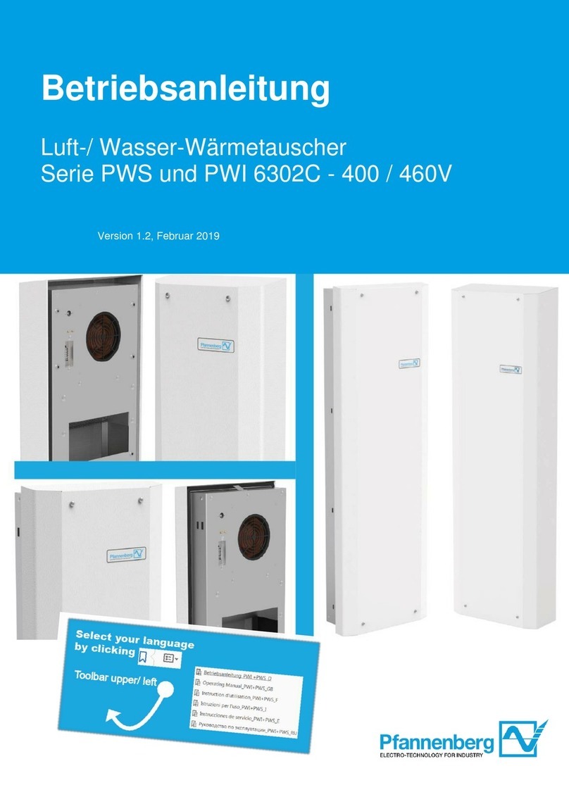
Pfannenberg PWS 6302C Series User manual
Pfannenberg
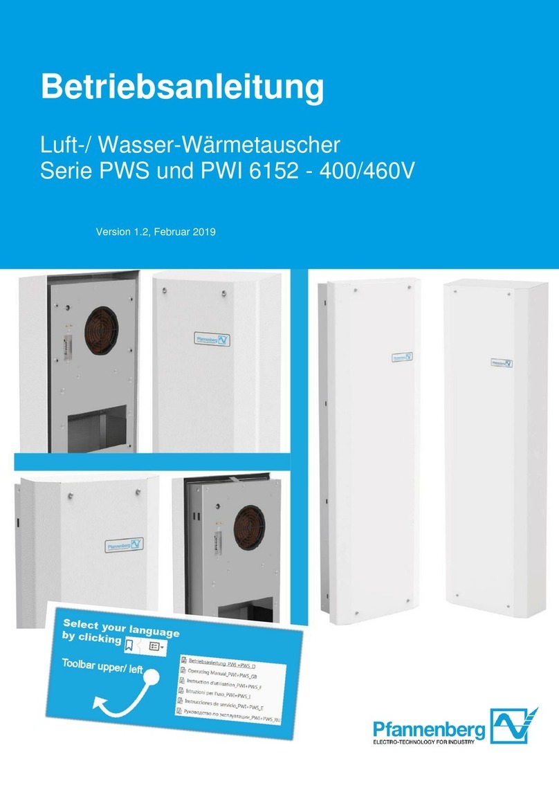
Pfannenberg PWS 6152 Series User manual
