Reliable N2-Blast DDX Maintenance manual

Reliable Automatic Sprinkler Co., Inc., 103 Fairview Park Drive, Elmsford, New York 10523
Model DDX N2-Blast®PrePaK™
Type F Preaction System
2” (50mm), 2-1/2” (65mm),
3” (80mm), 4”(100mm)
Bulletin 736 August 2020
Instructions for
Installation, Operation,
Care and Maintenance
Double Interlock
Electric/Pneumatic Release
General Description
The Reliable Type F Model DDX PrePaK system with in-
tegrated nitrogen generation is a completely self-contained,
supervised preaction system that can be readily installed
within a floor space of less than 7 ft2(0.65 m2) (not including
door swing). Refer to Fig. 1 for cabinet dimensions. Instal-
lation of the PrePaK system (not including exterior devices,
i.e., detectors and alarm bells), requires just three piping
connections. These connections are the water supply, the
sprinkler system and the drain. Reference locations of these
piping connections are shown in Fig. 1. Independent electri-
cal supplies are required for the optional system air com-
pressor (115 or 220 VAC), the optional Potter Model 4410
Releasing Control Panel (115/220 VAC), and the nitrogen
generator (115 VAC).
Full assembly drawings for the units are available on the
Reliable Automatic Sprinkler Company website (www.reli-
ablesprinkler.com)
The Reliable Model DDX N2-Blast®PrePaK system incor-
porates a South-Tek Systems FPS-900 pressure swing ad-
sorption N2-Blast®nitrogen generator, complete with inde-
pendent air compressor, nitrogen storage tank, and control
system. The nitrogen generator is completely wired, tested,
and integrated with the Model DDX PrePaK system, and
supplies 98% pure nitrogen to the piping network to limit
electrochemical, galvanic, and micro-biologically influenced
corrosion (MIC). Operation and maintenance information
can be found in this bulletin as well as at the South-Tek Sys-
tems website (www.southteksystems.com).
The Reliable Type F PrePaK system utilizes an optional Pot-
ter Model PFC-4410-RC Releasing/Control Panel. This fully
programmable, microprocessor-based releasing panel is
Underwriters Laboratories, Inc. Listed and is in compliance
with NFPA 13 and NFPA 72. Because the PFC-4410-RC is
totally zone and output programmable, the Reliable Type F
PrePaK system can be utilized in many different preaction
applications without having to rewire any of the factory in-
stalled devices. Once the previously described connections
are completed, the 24 VDC detectors, output devices, and
relay contacts may be connected to achieve the desired
system implementation.
8 psi - 24 psi (0.6 bar - 1.7 bar)
System Air/Nitrogen Pressure
Note: N2-Blast®and Blast-off®are registered trademarks of
South-Tek Systems, LLC.

2.
The Type F PrePaK system is designed specifically for
double interlock applications. Reliable double interlock pre-
action systems are designed for water sensitive areas that
require protection from inadvertent water flow into the sprin-
kler system piping.
The major benefits of a double interlock preaction System,
when compared with a wet pipe system, are as follows:
A. A fire alarm sounds prior to the flow of water from
a sprinkler, which may enable extinguishment of
the fire by handheld means before the operation
of any sprinkler occurs.
B. An annunciator signals whenever the integrity of
piping or sprinklers is accidentally or intentionally
disturbed; however, no water flow occurs at that
time.
C. Detection and notification of a fire condition are
provided by fire detectors, without the delay as-
sociated with water delivery time in the event of
a fire. Note that with a wet pipe system, the fire
alarm is delayed until after water has begun flow-
ing from and operated sprinkler.
To flow water into the system piping of a Type F double
interlock preaction system, two events must take place:
1) A fire detection device must detect heat and/or
smoke thereby causing the releasing/control panel
to energize the normally-closed solenoid valve.
2) The sprinkler system piping must discharge enough
supervisory air for the Model LP Dry Pilot Actuator
to operate. This is generally the result of a sprinkler
operating due to fire.
In the event that the system piping is ruptured, or a sprin-
kler head is accidentally opened, the Model LP Dry Pilot
Actuator will open and a low system air pressure alarm will
sound. The Model DDX Deluge Valve, however, will not be
released to flow water since the solenoid valve still remains
closed. Conversely, in the event of a false detection signal,
the releasing/control panel will activate an alarm, but the
Model DDX Deluge Valve will not flow water due to the fact
that the Model LP Dry Pilot Actuator remains closed.
When using the Reliable Type F PrePaK system in double
interlock applications the sprinkler system is pressurized (su-
pervised) with air provided by the optional factory-installed
air compressor (or on-site Nitrogen supply) and is monitored
by a system pressure switch. If Nitrogen is used as the su-
pervisory gas, an optional Nitrogen Kit is available. This kit
contains a regulator and an additional pressure switch that
is used to monitor any low pressure conditions that may
arise due to having a limited Nitrogen supply. The optional
factory-installed air compressor can be utilized for make-up
air until the Nitrogen supply can be replenished.
Note: Compressed air is not to be considered as dry air
and may create ice plugs in the sprinkler system piping.
A Model B Hydraulic Manual Emergency Releasing station
is standard equipment in the Type F PrePaK system. It con-
sists of an aluminum nameplate mechanically attached to a
ball valve. The valve handle in its OFF position is guarded
against accidental turning to the ON position (and system
discharge) by a nylon cable tie provided with the PrePaK
system assembly. The cable tie is designed to allow, in case
of an emergency, forceful turning of the valve handle to the
ON position.
Approvals
• The Model DDX N2-Blast PrePaK Type F preaction sys-
tem is FM Approved as a factory-assembled Preaction
System to Approval Standard 1011/1012/1013, Deluge
and Preaction Sprinkler Systems.
• The Model DDX deluge valve and Type F preaction trim
are FM Approved and cULus Listed.
• The South-Tek N2-Blast® Model FPS-900-RS nitrogen
generator is FM Approved to Approval Standard 1035,
Nitrogen Generators for Corrosion Mitigation.
Technical Data
1. The Reliable Model DDX Type F PrePaK system is
rated for a minimum water supply pressure of 20 psi
(1.4 bar). When fitted with the optional 300 psi (20.7
bar) solenoid, the 2”, 2-1/2”, 3”, and 8” sizes are
rated for a maximum pressure of 250 psi (17.2 bar),
and the 4” and 6” sizes are rated for a maximum
pressure of 300 psi (20.7 bar). Water temperature
must be maintained between 40°F and 140°F (4°C
and 60°C).
2. Friction loss, expressed in equivalent length of
Schedule 40 pipe and based on Hazen-Williams
Formula is:
System Size: Equivalent Length
2” (50mm) 19.4 ft (1.3 m)
2½” (65mm) 24.5 ft (1.8 m)
3” (80mm) 28.9 ft (3.8 m)
4” (100 mm) 32.8 ft (17.7 m)
These values account for the Model DDX Deluge Valve,
supply manifold tee, butterfly control valve, and small
pipe/manifold located directly above Model DDX Deluge
Valve.
3. Shipping Weight:
System Size Weight
2” (50mm)
950 lbs (431 kg)2-1/2” (65mm)
3” (80mm)
4” (100 mm) 1075 lbs (488 kg)
4. Please reference Figure 1 for dimensions.
The following is a list of Technical Data Bulletins which de-
scribe the valves and devices which are used in the system:
Device Reliable Bulletin #
(unless otherwise noted)
Model DDX Deluge Valve Reliable Bulletin 519
Type F Double Interlock Preaction Trim Reliable Bulletin 751
Low Air Pressure Switch Potter, 5401564
Alarm Pressure switch Potter, 5400928
Releasing Control Panel Potter Manual #5403550

3.
Fig. 1

4.
Hydrostatically testing the valve and trim to pressures higher
than their rating is limited to the hydrostatic test as referenced
by NFPA13. It does not address the occurrence(s) of a “wa-
ter hammer” effect, which can indeed damage the valve. A
“water hammer” in the water supply piping of the valve can
create pressures in excess of the rated pressure and should
be avoided by all necessary means. This condition may be
created from improper fire pump settings, underground con-
struction work, or an improper venting of trapped air in the wa-
ter supply piping.
System Air / Nitrogen Pressure Requirements
The Model DDX Type F PrePaK system includes gauges in-
dicating the pneumatic and water pressures of Model LP Dry
Pilot Actuator. Table A specifies the air or nitrogen pressure
level to be applied to the Actuator. The factory installed Pres-
sure Maintenance Device in the unit automatically provides
adequate makeup air or nitrogen flow to maintain supervisory
pressure with normal leakage for the system piping, while re-
stricting the flow of makeup air or nitrogen to allow for system
operation. Please note that when the optional Model B1 Ac-
celerator is to be utilized to expedite water-delivery time, the
pneumatic pressure must be not less than 15 psi (1.0 bar).
Table A
The following table provides a quick reference to the vari-
ous programs (found in this bulletin and the Potter Manual
#5403550) that may be utilized with a Type F PrePaK sys-
tem:
Desired Application Program
Single Interlock,
Single Zone
Potter Program #6
(Factory Setting)
Single Interlock,
Cross-Zoned Potter Program #7
Note: The Model DDX Type F PrePaK Double Interlock Preaction
system utilizes a solenoid controlled by single interlock program-
ming in conjunction with a pneumatic (mechanical) actuator.
Installation Requirements
The automatic sprinklers, releasing devices, fire
detection devices, manual pull stations, and signaling
devices which are utilized with the Reliable Model DDX
Type F PrePaK system must be UL and/or ULC Listed or
FM Approved, as applicable.
The steel enclosure and all the interconnecting piping
must be located indoors in a readily visible and acces-
sible location and in an area that can be maintained at a
minimum temperature of 40°F (4°C). Note: Heat tracing
is not permitted. The solenoid valve is operated and
supervised by the Potter Model PFC-4410-RC Releas-
ing Control Panel. Details on the electrical connections
of this system to the Potter Panel can be found in the
Potter Manual #5403550, Installation, Operation and
Instruction of PFC-4410-RC Releasing Control Panel
(this manual is included with other pertinent manuals
and shipped inside the enclosure). This panel is fully
zone and output programmable and may be adapted to
several applications. Hydrostatic Testing of DDX Valves
and DDX Systems.
Hydrostatic Testing of DDX Valves and
DDX Systems
As required by NFPA 13, fire sprinkler systems with work-
ing pressures up to and including 150 psi are to be hydro-
statically tested at a water pressure of 200 psi. Fire sprinkler
systems with working pressures above 150 psi are required to
be hydrostatically tested at 50 psi above the system working
pressure. In addition to the hydrostatic tests described above,
dry pipe and double interlock preaction systems require an
additional low pressure air test.
In some cases, hydrostatic testing (in accordance with the
NFPA 13 requirements noted above) will result in pressures
that exceed the working pressure of the valve and trim kit for
the two-hour test period. The valve and applicable trim kit have
been tested, approved and listed under these conditions and
as such, hydrostatic testing in accordance with NFPA 13 is ac-
ceptable. In addition, the clapper can remain in the closed po-
sition and the trim kit need not be isolated, as each has been
designed to withstand hydrostatic testing as required by NFPA
13.
Water Pressure psi (bar) System Air or Nitrogen Pressure
psi (bar)
Maximum Not Less Than
20 (1.4) 8 (0.6)
30 (2.1) 10 (0.7)
50 (3.4) 12 (.8)
75 (5.2) 13 (.9)
100 (6.9) 15 (1.)
125 (8.6) 16 (1.1)
150 (10.3) 17 (1.2)
175 (12.1) 18 (1.2)
200 (13.8) 19 (1.3)
225 (15.5) 21 (1.4)
250 (17.2) 22 (1.5)
275 (19.0) 23 (1.6)
300 (20.7) 24 (1.7)
Notes:
1. Supervisory air or nitrogen pressure should not exceed 30 psi (2.1
bar). Excess pressure may result in damage to the actuator.
2. Fastest valve operation is achieved with supervisory air or nitrogen
pressure indicated; however, pressure must never be less than the
minimum specified in the table above.
3. Air maintenance devices that maintain a constant pressure are
recommended; however, if a tank-less compressor is used, the
“compressor on” setting of the pressure switch must never be lower
than the minimum pressure in the table above.

5.
When the air compressor in the Model DDX Type F PrePaK
system is used to initially fill the sprinkler system with air, the
steel enclosure door should remain open to provide maxi-
mum intake air flow to the air compressor. The air compressor
is connected to a storage tank. This tank functions as a res-
ervoir, providing make-up air to compensate for small, inter-
mittent leaks in the sprinkler system. It should be noted that
significant leaks may overburden this storage tank, thereby
causing the air compressor to continuously cycle on and off.
The factory-installed system air pressure switch may need
on-site adjustment to correspond with the air pressure val-
ues found in Table A. Adjustment, if required, should be
made according to Potter Bulletin 5401564 included with
the switch.
System Electrical Requirements
All releasing, alarm, and detection devices in the Reli-
able Model DDX Type F PrePaK system are supervised by
a Potter Model PFC-4410-RC Releasing Control Panel. All
of the terminals are translated to a water-tight terminal box
mounted on the interior of the enclosure. All field wiring is
connected to this terminal box. Note: The EOL (End of Line)
resistors have also been relocated.
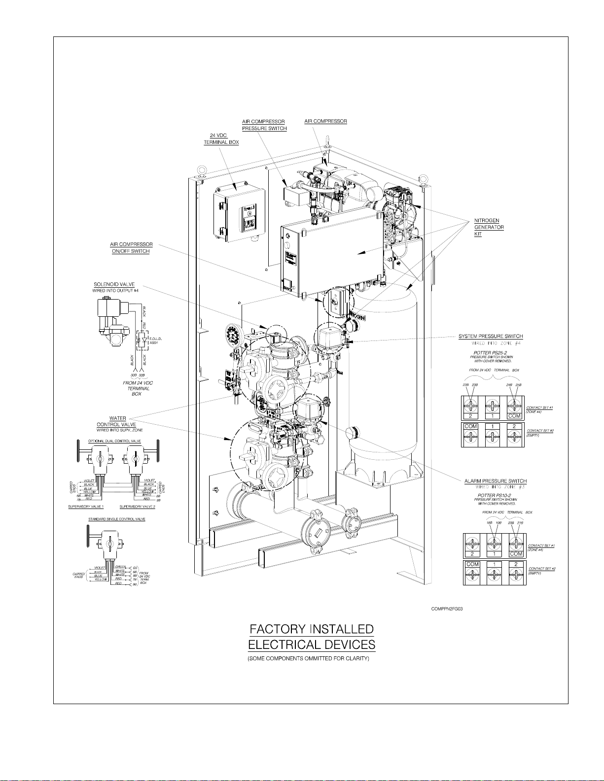
The Reliable Model DDX PrePaK system is delivered
with six factory-installed electrical devices. They consist of
the following:
1. A system air pressure switch, which is used to monitor
sprinkler piping.
2. An alarm pressure switch, which indicates an actuation
of the deluge valve.
3. A normally-closed, releasing solenoid valve, which is
used to actuate the deluge valve.
4. A 1/2 HP (2”, 2-1/2”, & 3” valve) or 1 HP (4” valve) air
compressor with tank.
5. A supervised butterfly (main control) valve (Note: A sys-
tem side butterfly valve is available as an option).
6. A release control disable switch (RCDS) which is used
to disable the solenoid valve for test purposes.
The factory electrical connections of these devices,
along with information on the connection of detection devic-
es (initiating zones 1 and 2), signaling devices, and super-
visory outputs to the Potter PFC4410-RC Releasing Control
Panel are included in this bulletin. The power supply, stand-
by emergency power supply, battery charger and rectifier
circuitry are all contained within the PFC4410 panel. Bat-
teries that provide 90 hours of standby power are provided
with the panel. For additional information and detailed wiring
diagrams, please refer to Potter Manual #5403550 (Instal-
lation, Operation and Instruction of PFC4410-RC Releasing
Control Panel).
Note: In order for the solenoid valve to maintain a warranty it
must remain sealed as it came from the factory. If there are
concerns about the valve’s internal components, immediate re-
placement is recommended.
System Operation (Double Interlock)
To fully activate (discharge water from) the Reliable Model
DDX Type F PrePaK system, a fire detection device must ac-
tivate and pneumatic pressure must be lost from the sprin-
kler system piping (normally from the activation of one or
more fire sprinklers).
When the system is properly set for service, the water sup-
ply pressure simultaneously acts on both the underside of
the deluge valve’s clapper and on the valve’s push rod by
means of the pressurized push rod chamber. The resultant
pressure force acting on the push rod, in unison with the me-
chanical advantage of the deluge valve lever, is more than
sufficient to hold the valve clapper in the closed position
against the water supply pressure.
Energizing the releasing solenoid valve is only one of the
events required towards opening the deluge valve. Air pres-
sure in the sprinkler system must also be reduced to a level
low enough to activate the Model LP Dry Pilot Actuator. Both
of these events allows the deluge valve’s push-rod chamber
to be vented to drain through its outlet. Since the push-rod
chamber pressure cannot be replenished through the inlet
restriction as rapidly as it is vented, the pressure falls rapidly.
When the push-rod chamber pressure drops below one-
third of the water supply pressure, the force acting beneath
the valve clapper becomes greater than the push-rod force
acting on the lever which causes the clapper to open. Refer
to Reliable Technical Bulletin 751 for further details.
Once the clapper has opened, the lever acts as a latch,
preventing the clapper from returning to the closed position.
Water from the supply flows through the deluge valve into
the system piping and also through the alarm outlet to acti-
vate water flow alarm devices. Note that the solenoid valve
will be maintained open by the Potter Model PFC-4410-RC
Releasing/Control Panel latching feature until it is reset for
operation.
After system shutdown and draining, the Model DDX Del-
uge Valve clapper is easily reset without special tools us-
ing the external reset feature. Restore detection devices by
resetting or replacing any operated device. Once detection
devices are restored the system can be reset (see Resetting
Model DDX Type F Double Interlock Preaction System).
Resetting Model DDX Type F Double Interlock
Preaction System
1. Close the valve controlling water supply to the Del-
uge Valve and close the air or nitrogen supply to the
sprinkler system.
2. Close the pushrod chamber supply valve.
3. Open main drain valve and drain system.
4. Open all drain valves and vents at low points through-
out the system, closing them when flow of water has
stopped. Open the Model B Manual Emergency Station
to relieve pressure in the pushrod chamber of the Deluge
Valve.
5. With the alarm line valve open, push in the plunger of
ball drip valve, forcing the ball from its seat, and drain the
alarm line.

6.
6. With the Model B Manual Emergency Station open,
push in and rotate the Deluge Valve’s external reset knob
counterclockwise (when facing the valve), until you hear
a distinct noise indicating that the clapper has reset.
Note: The reset knob can be rotated only while pressure
in the pushrod chamber is vented to atmospheric condi-
tions (0 psig).
7. Inspect and replace any portion of the detection sys-
tem and/or sprinkler system subjected to fire conditions.
8. Open the pushrod chamber supply valve and allow
water to fill the pushrod chamber. Close the Model B
Manual Emergency Station.
9. Purge all air from the actuation piping: Open the sole-
noid valve by operating a detector or an electric manual
emergency station. Note that the Model LP Dry Pilot Ac-
tuator should also be open since there is no pneumatic
pressure on the system.
10. While water is flowing through the solenoid valve
AND the actuator, cause the actuator to close first by ap-
plying air or nitrogen pressure to the system.
11. Open the air or nitrogen supply quick fill valve to re-
store supervisory pressure in the sprinkler system and
close the dry pilot actuator. Allow the pressure to build
to the level specified in Table A, then set the pneumatic
supply to automatic operation. (Note: To build supervi-
sory air pressure in the sprinkler system, it may be nec-
essary to temporarily close the main drain valve and the
alarm line valve until air pressure has built up to the rec-
ommended level.)
12. After the Model LP Dry Pilot Actuator has been set,
close the solenoid valve by resetting the release control
panel. (All detectors and manual pull stations must be in
a normal state before the panel can be reset.)
Note: It is important that the piping between the sole-
noid valve and the dry pilot actuator is filled with water
and not air. This is accomplished by closing the dry pilot
actuator FIRST while water is flowing through the device
and closing the solenoid valve only AFTER the actuator
is completely set.
13. Open the alarm line valve. Verify the main drain valve
is open. Slightly open the main valve controlling water
supply to the Model DDX Deluge Valve, closing the main
drain valve when water flows. Observe if water leaks
through the ball drip valve. If no leak occurs, the Deluge
Valve clapper is sealed. Slowly open the main valve con-
trolling water supply until fully open and verify that it is
properly monitored.
14. Verify that the pushrod chamber supply valve and
alarm line valve are open. The pushrod chamber supply
valve must remain open when the Deluge Valve has been
reset, to maintain water pressure in the pushrod cham-
ber.
15. Verify that the Model B Manual Emergency Station is
secured in the OFF position with the appropriate nylon
tie.
Inspection and Testing
1. Water supply — Confirm that valves controlling water
supply to the Deluge Valve are opened fully and properly
monitored.
2. Alarm line — Confirm that the alarm line valve is open
and remains in this position.
3. Other trim valves — Confirm that the pushrod cham-
ber supply valve is open, as well as all pressure gauge
valves. The main drain valve, condensate drain valve,
and alarm test valve should be closed.
4. Ball drip valve — Push in on the plunger to be sure
ball check is off its seat. If no water appears, the Deluge
Valve water seat is tight. Inspect the bleed hole on the
underside of the pushrod chamber for leakage.
5. Dry pilot trim — Inspect air pressure for conformance
to Table A.
6. Releasing device — Check outlet of the releasing de-
vice (i.e., solenoid valve and hydraulic manual emergen-
cy station) for leakage. Also verify that tubing drain lines
from releasing devices are not pinched or crushed which
could prevent proper releasing of the Deluge Valve.
7. Testing alarms — Open the alarm test valve permit-
ting water from the supply to flow to the electric sprinkler
alarm switch and to the mechanical sprinkler alarm (wa-
ter motor). After testing, close this valve securely. Push
in on the plunger of ball drip valve until all water has
drained from the alarm line.
8. Operational test — Open the Model B Manual Emer-
gency Station. Alternatively, operate the electrical detec-
tion system and deplete pneumatic pressure from the
sprinkler system.
Note: AN OPERATIONAL TEST WILL CAUSE THE DEL-
UGE VALVE TO OPEN AND FLOW WATER INTO THE
SPRINKLER SYSTEM.
9. Secure the Model B Manual Emergency Station in the
OFF position with nylon tie after Deluge Valve is reset.
Testing Detection System Without Operating
Deluge Valve
1. Close the valve controlling water supply to the del-
uge valve and open the main drain valve.
2. Verify that valve supplying hydraulic pressure to the
piston/pushrod chamber is open, allowing water to enter
the pushrod chamber.
3. Operate the electrical detection system and deplete
pneumatic pressure from the sprinkler system.
4. Operation of the detection combined with loss of
pneumatic pressure must result in a sudden drop of wa-
ter pressure in the pushrod chamber, as indicated by the
pressure gauge on the hydraulic release trim.
5. Reset the valve per the reset instructions.

7.
Maintenance
The owner is responsible for maintaining the fire protec-
tion system in proper operating condition. Any system
maintenance or testing that involves placing a control
valve or detection/control system out of service may
eliminate the fire protection that is provided by the fire
protection system.
The Reliable Model DDX valve and associated equip-
ment shall periodically be given a thorough inspection
and test. NFPA 25, “Inspection, Testing, and Mainte-
nance of Water Based Fire Protection Systems,” provides
minimum maintenance requirements. System compo-
nents shall be tested, operated, cleaned, and inspected
at least annually, and parts replaced as required. Re-
place any components found to be corroded, damaged,
worn, or non-operable. Increase the frequency of inspec-
tions when the valve is exposed to corrosive conditions
or chemicals that could impact materials or operation of
the assembly.
If face plate is removed during maintenance, torque face
plate bolts to the following values during re-installation:
35 ft-lbs. (47 N-m) for 2” through 4” valves
70 ft-lbs. (95 N-m) for 6”-8” valves
Draining Excess/Condensate Water from the
System
1. Notify the owner and monitoring company that main-
tenance is being performed on the system.
2. Close the main water control valve.
3. Open the Main Drain Valve.
4. Open the Condensate Drain Valve until all water has
drained.
5. Close Condensate Drain Valve.
6. Partially open the Main Water Control Valve.
7. Slowly close the Main Drain Valve.
8. Fully open the Main Water Control Valve.
9. Notify the owner and monitoring company that the
system has been returned to service.
SOLENOID VALVE INSPECTIONS, TESTS
AND MAINTENANCE
WARNING: THE OWNER IS RESPONSIBLE FOR
MAINTAINING THE FIRE PROTECTION SYSTEM IN
PROPER OPERATING CONDITION. ANY SYSTEM
MAINTENANCE OR TESTING THAT INVOLVES PLAC-
ING A CONTROL VALVE OR DETECTION SYSTEM
OUT OF SERVICE MAY ELIMINATE THE FIRE PRO-
TECTION OF THAT SYSTEM. PRIOR TO PROCEED-
ING, NOTIFY ALL AUTHORITIES HAVING JURIS-
DICTION. CONSIDERATION SHOULD BE GIVEN TO
EMPLOYMENT OF A FIRE PATROL IN THE AFFECT-
ED AREA.
WARNING: PRIOR TO OPERATING THE SOLENOID
VALVE, BE SURE TO CLOSE THE SYSTEM CONTROL
VALVE TO AVOID UNINTENTIONAL OPERATION OF
THE DELUGE VALVE
1. Inspections: It is imperative that the system be in-
spected and tested in accordance with NFPA 25 on
a regular basis. The frequency of the inspections
may vary due to contaminated water supplies, cor-
rosive water supplies, or corrosive atmospheres. In
addition, the alarm devices, detection systems, or
other connected trim may require a more frequent
schedule. Refer to the system description and ap-
plicable codes for minimum requirements.
2. The valve must be inspected at least monthly for
cracks, corrosion, leakage, etc., cleaned and re-
placed as necessary.
3. If leakage is suspected through the solenoid valve, it
should be replaced.

8.
Fig. 2
Note: Trim valve location is common to wet pilot
line, dry pilot line, and electric release systems.

9.
Fig. 3

10.
Fig. 4

11.
Fig. 5

12.
Fig. 6

13.
Fig. 7

14.
Fig. 8 — Wiring Diagram

15.
Fig. 9 — Wiring Diagram

16.
POTTER PROGRAM #6
OUTPUTS
ZONES
Supervisory 2 (1)
#1
Conventional (2)
#2
Conventional(2)
#3
Waterflow
#4
Low Air Supervisory
#1 ALARM X
#2 WATERFLOW X
#3 SUPERVISORY X X
#4 RELEASE X
Single Interlock, Single Detection Zone
Potter Program #6
1. Apply power to panel.
2. Slide the program switch down.
3. Press the FUNCTION button until the display reads
“PASSWORD=000.”
4. To enter a password, press the SELECT button until
the proper number is displayed above the “^” sym-
bol; then press the SET button to move to the next
digit. After entering the third number the display will
change. (All panels are shipped with a “000” pass-
word.)
5. Press the FUNCTION button until the display reads
“PROGRAM ##.” (the second “#” character refers to
the current program number between “0” and “24”).
6. Press the SELECT button until the display reads
“PROGRAM #6.”
7. Press the SET button
8. The panel is completely programmed except for the
custom banner and zone messages. Slide the pro-
gram switch back up.
INPUTS: 1 conventional zone, 1 manual release zone, 1 waterflow zone, 1 low air zone, 1 supervisory zone.
OUTPUTS: 1 general alarm bell, 1 waterflow bell, 1 supervisory bell, 1 solenoid release circuit.
OPERATION: Activation of either conventional zone (or operation of the manual pull station within the PrePaK system
cabinet) will operate the solenoid release circuit and the general alarm bell. Activation of the waterflow
zone will operate the waterflow bell. Activation of either the low air zone or the supervisory zone will
operate the supervisory bell. When either Zone #1 or #2 is in alarm, Output #1 (general alarm) and
Output #4 (solenoid release) will operate. When Zone #3 is in alarm, Output #2 (waterflow bell) will
operate. When either Zone #4 or the supervisory zone is activated, Output #3 (supervisory bell) will
operate.
Note:
(1) The Butterfly valve in the PrePaK system assembly is connected to Supervisory 2 input of the Potter PFC-4410RC
Releasing/Control panel
(2) The emergency manual release within the PrePaK system cabinet is wired into the conventional detection zones 1 and 2, and is
designed to release the solenoid for setup and testing purposes.
For additional Information, please refer to the “Installation, Operation, and Instruction Manual” for the Potter
PFC4410-RC Releasing Control Panel (provided with the unit).

Single Interlock, Cross Zoned Detection
Potter Program #7
1. Apply power to panel.
2. Slide the program switch down.
3. Press the FUNCTION button until the display reads
“PASSWORD = 000.”
4. To enter a password, press the SELECT button until
the proper number is displayed above the “^” sym-
bol; then press the SET button to move to the next
digit. After entering the third number the display will
change. (All panels are shipped with a “000” pass-
word).
5. Press the FUNCTION button until the display reads
“PROGRAM ##.” (the second “#” character refers to
the current program number between “0” and “24”).
6. Press the SELECT button until the display reads
“PROGRAM #7.”
7. Press the SET button.
8. The panel is completely programmed except for the
custom banner and zone messages. Slide the pro-
gram switch back up.
INPUTS: 2 conventional zones (cross-zoned), 1 waterflow zone, 1 low air zone, 1 supervisory zone.
OUTPUTS: 1 general alarm bell, 1 waterflow bell, 1 supervisory bell, 1 solenoid release circuit.
OPERATION: Activation of both conventional zones at the same time (or operation of the manual pull station within
the PrePaK system cabinet) will operate the solenoid release circuit and the general alarm bell. Activa-
tion of either conventional zone will operate the general alarm bell. Activation of the waterflow zone will
operate the waterflow bell. Activation of either the low air zone or the supervisory zone will operate the
supervisory bell. When either Zone #1 or #2 is in alarm, Output #1 (general alarm) will operate. When
Zones #1 and #2 are in alarm at the same time, Output #4 (solenoid release) and Output #1(general
alarm) will operate. When Zone #3 is in alarm, Output #2 (waterflow bell) will operate. When either
Zone #4 or the supervisory zone is activated, Output #3 (supervisory bell) will operate.
Note:
(1) The Butterfly valve in the PrePaK system assembly is connected to Supervisory 2 input of the Potter PFC-4410RC
Releasing/Control panel
(2) The emergency manual release within the PrePaK system cabinet is wired into the conventional detection zones 1 and 2, and is
designed to release the solenoid for setup and testing purposes.
For additional Information, please refer to the “Installation, Operation, and Instruction Manual” for the Potter
PFC4410-RC Releasing Control Panel (provided with the unit).
POTTER PROGRAM #7
OUTPUTS
ZONES
Supervisory 2 (1)
#1
Conventional (2)
#2
Conventional(2)
#3
Waterflow
#4
Low Air Supervisory
#1 ALARM X X
#2 WATERFLOW X
#3 SUPERVISORY X X
#4 RELEASE XX XX
17.

FPS-900-RS Nitrogen Generator
General
This manual provides instruction for the proper use and
maintenance of South-Tek Systems N2-Blast®FPS-900-
RS. South-Tek Systems and Reliable are not responsible
for damages when using this in manners not approved by
South-Tek Systems and Reliable. The user(s) of this docu-
ment should confer any questions with a qualified South-
Tek Systems representative on its commissioning and
correct use. Please contact South-Tek Systems with any
question or concerns at:
South-Tek Systems, LLC
2940 Orville Wright Way Ste 600
Wilmington, NC, 28405
Tel: (888) 526-6284
Email: [email protected]
http://www.southteksystems.com/
Important Information
All personnel (and their supervisors) installing, operating,
and maintaining the N2-Blast®must read and fully under-
stand this manual prior to installing, operating or perform-
ing maintenance. The N2-Blast®produces nitrogen (N2)
at a low flow rate, which quickly dissipates into the air. N2
gas is not poisonous, but do not directly inhale since high
concentrations can cause asphyxiation. Install the unit in a
well-ventilated room that is not sealed off from normal living
space air changes. All personnel involved with the instal-
lation, operations, and maintenance of the N2-Blast®must
follow safe working practices, including OHSA and local
health/safety code regulations.
Safety Guidelines
The following section outlines the basic safety consid-
erations about installation and operation of the N2-Blast®
FPS-900-RS. For other equipment used with the nitrogen
generator, such as external air compressors, and dryers,
refer to the manufacturer’s safety guidelines.
Using the N2-Blast®FPS-900-RS correctly is impor-
tant for safety and trouble-free operation. Wrong use can
cause damages to the system or can lead to incorrect gas
supply. The nitrogen generator produces nitrogen at a low
flow rate, which quickly dissipates into the air. Nitrogen is
not poisonous, but do not directly inhaled, since high con-
centrations, can cause asphyxiation. Install the unit in a
well-ventilated room, unsealed off from normal living space
air changes.
Warning: Install the unit in a within a well-ventilated room,
one that is not sealed off from normal living space air
changes.
Read carefully and act accordingly before operating
or repairing the unit:
• The operator must use safe working practices and
rules when running the nitrogen generator.
• The owner is responsible for always keeping the unit in
safe working conditions.
• Always use approved parts when performing mainte-
nance and repairs. Make sure that replacement parts
meet or exceed the original parts’ specification.
• Only competent individuals, trained and authorized,
can install, operate, perform maintenance and repair.
• Isolate incoming and outgoing pressures to the gen-
erator, and depressurize the service or repair section
before performing any mechanical work, including
changing the filters.
• Vent the nitrogen generator’s exhaust gas outside or to
a large, well-ventilated room to avoid suffocation due
to lack of oxygen.
• Wear safety glasses if the cabinet door is open while
the machine is running.
• Use ear protection when the equipment is running.
NOTE: Always following local and site safety regula-
tions in conjunction with this manual. Correct use of
the nitrogen generator is important for personal safety.
Incorrect safety practices can cause damage to the in-
dividual and equipment.
Follow safe working practices, OSHA, and local health
and safety regulation when maintaining the N2-Blast® FPS-
900-RS.
Air Supply
The N2-Blast®FPS-900-RS includes a built-in air com-
pressor to supply gas to the nitrogen generator. It is not for
performing quick fills; a separate suitable air compressor
should be used to fill the system.
Electrical Requirements
The N2-Blast®FPS-900-RS requires 120VAC / 50-
60hz / 1ph and draws < 8A. A 240VAC option is also avail-
able. It has a built-in 20A over-current protection device
and comes with a standard 3-prong US power cord for
the electrical connection (unless otherwise specified). It
comes with UL 508A ICP certification, and the electrical
schematics are available upon request.
Site Specifications
Unless designed otherwise, install in a nonhazard-
ous indoor location with temperatures between 40-100°F
(4°- 38°C). For ease of maintenance, troubleshooting, and
minimizing pressure drop, install the equipment in the
same area. Leave enough space around the generator
and other equipment for routine maintenance.
18.

Key Features
Air Compressor
An oil-less internal air compressor has an engineered
dampening system reducing vibration and noise through-
out the cabinet. The air compressor has a pre-filter to
catch small particulates that can cause damage. The rec-
ommended replacement for the pre-filter is 1000 run hours
or 1-year, whichever comes first. Dirtier environments may
need more frequent changes. Consult with the supplier for
a different filter maintenance schedule if installing in a dirty
environment.
Air Filters
The generator has an air inlet pre-filters and two filters
between the compressed air and O2separation beds - the
particulate and coalescing. The 5-micron particulate filter
catches the bulk particles, and the 0.1 micron coalescing
catches the remaining smaller particles. Both filters fea-
ture an auto-drain that drains any water buildup within the
filter housing. These drain lines are on the cabinet’s bot-
tom right side. Connect these drain lines to a safe location.
Programmable Logic Controller
An integrated PLC within the cabinet that features
smart timing to maximize the generator’s performance. It
controls the valve timing and sequencing to move com-
pressed gas throughout the system. It also has a smart
feature to automatically switch between different “modes”
based on the current run stages (see Chapter 7: System
Operation for more about the unit’s functionality).
Safety Relief Valves
The installed ASME safety relief valves add additional
safety to protect component failures.
Nitrogen Tank
A nitrogen tank inside the cabinet comes with ball
valves, safety relief, and a gauge.
Automatic Cut-In and Cut-Out
The generator starts and stops based on a pressure
switch. Do not adjust the factory preset cut-in and out
pressure without first consulting with South-Tek Systems.
Patented BlastOff®– Leak Detection System
The “BlastOff® Leak Detection” is a patented feature
which sends an alarm if it detects a possible gas leak. The
alarm signal can be an audible, visual, and dry contact
connection to the “Building Management System (BMS)”.
Power cycle the unit to reset the alarm but avoid doing this
without finding the cause, as it will shorten the generator’s
life.
N2-Blast®FPS-900-RS Specifications
• Nitrogen Purity 98.5+%
• Integrated Installation in Reliable PrePaK system
• Display Hours/Power on/Operating
• N2Storage Pressure 60-70 PSIG (±5%)
• Cabinet Port Connections 1/2” NPT Female
• Electrical 110-220V / 50-60Hz / 1Phase; 20 Amp
Breaker
• Compressor Integral / Oil-Free
• Ambient Temperature 40° to 100°F
• Noise Level (dbA) < 90 dbA
Operation
The nitrogen generator uses valve sequencing to
produce nitrogen. The design meets specifications of a
fire protection system. Consult with South-Tek System for
written approval before performing any field changes or
customization. Unauthorized changes void all warranties
and may cause damages or malfunctions to the system.
This section describes the major control functions
and instrumentations associated with the nitrogen gen-
erators. All programs are proprietary and password pro-
tected from the factory. Do not alter any controls or instru-
mentations. Changes without South-Tek Systems’ written
consent voids the performance specifications.
Controller Modes
To utilize the buttons on the front of the controller the
unit must be in “S” or “Switch” mode and unlocked. If the
system is displaying “LOCK”, the Mode Select Button may
be pressed and held to unlock the controller (repeat this
step if a system lockout is desired). To change to Switch
Mode, press the Mode Select Button when the controller
is unlocked until the System Mode Indicator displays “S”.
This mode allows access to two features:
• Alarm Simulation (5) – Hold the Alarm Simulation But-
ton for 3 seconds or press the filter replacement reset
button 3 times within 3 seconds to activate. This will
simulate an alarm condition and trip the alarm dry
contact in the unit for 2 seconds so that proper func-
tioning can be confirmed.
• Filter Change Reset (0) – When a new FRP (Filter Re-
placement Kit) is installed, the 1000- hour filter change
time must be reset. After replacing the filter elements,
press and hold the Filter Change Reset Button for 7
seconds. An audible beep will confirm that the time is
reset and filter alarm will be reset. (Note: this will also
trigger the Customer Alarm Relay for one second)
19.

Normal Run/Standby Mode (run/StdbY)
“Run” mode is when the FPS-900-RS is producing ni-
trogen and supplying it to the storage tank. The system will
automatically enter “Standby” mode when the tank is fully
pressurized (70 PSIG ±5 PSIG). It will remain in “Standby”
mode until the tank pressure falls 7-10 psig.
To run the system in normal run mode:
1. Connect power to the system.
2. Open the nitrogen generator’s 3-way outlet ball valve
to nitrogen-out position.
3. On the nitrogen tank, open the gas inlet valve.
4. Push the On/Off toggle button on the upper right con-
trol panel to the “On” position (up) and the system will au-
tomatically turn on and start filling the storage tank with
nitrogen.
To stop the system:
1. Switch the nitrogen generator’s 3-way outlet ball valve
to the bypass position.
2. System will automatically stop once it reaches the cut-
out pressure of approximately 65-75 PSIG.
3. In the case of an emergency shut off, push the On/Off
toggle button on the upper left control panel to the “Off”
position. The unit will shut down immediately.
Alarm Mode
When an alarm mode is activated, it will trigger the
audible buzzer, alarm contact, and flash the cause of the
alarm on the screen. The customer alarm contact wiring
can be viewed on the supplied wiring diagram. The cus-
tomer alarm dry contact is constantly energized and will
constantly illuminate the LED indicator on top of the con-
tact. This is so when there is no power or power is lost
on the system, the contact will de-energize and show a
fault condition. The alarm contact has a max rating of 6A at
250VAC and 2A at 24VDC.
Bypass Mode (BPASS)
During the 30-minute fire protection piping system fill
test or an issue with the generator is detected, the opera-
tor can switch the system into manual bypass mode by
turning the handle on the 3-way ball valve to the bypass
position. With the handle in the “Bypass Mode”, the by-
pass alarm triggers the audible buzzer, alarm contact, and
flashes “BPASS” on the controller’s 7-segment display. The
alarm will turn off once the handle is back to normal run
position.
BLASTOFF® Alarm Mode (B-Off)
The nitrogen generator activates a BlastOff® Alarm
when it detects potential leaks or nitrogen being over-
drawn. The BlastOff® Alarm will trigger the audible buzzer,
alarm contact, and flash “B-OFF” on the controller’s 7-seg-
ment display. Inspect and test the system for leaks and
component failures. Power cycle the unit to reset the alarm
but avoid doing this without finding the cause, as it will
shorten the generator’s life. Contact South-Tek System or
the local installer for further troubleshooting.
Low System Pressure Alarm Mode (Lo-n2)
The low system pressure alarm activates when a sys-
tem pressure is detected below the normal functioning lim-
its of the nitrogen generator. This may be from an issue with
the generator, a supply valve being shut off, or caused by
a large leak in the fire protection system.
Power Loss Alarm Mode (-----)
The Power Loss alarm activates when the nitrogen
generator loses power for any reason. This will cause the
alarm contact to trigger.
Filter Replacement Alarm Mode (FILTr)
Once the generator has been running for 1000 hours
or more, the filter replacement alarm will activate. Re-
place the filters according to Section 9 Maintenance. Af-
ter replacing the filter elements, press and hold the Filter
Change Reset Button for 7 seconds. An audible beep will
confirm that the time is reset, and filter alarm will shut off if it
is active. (Note: resetting this will also trigger the Customer
Alarm Relay for one second)
Start-up Procedures
Use caution when working with pressurized gas. Al-
ways leak check every line before using the system. Note:
Line leaks will cause the N2-Blast®FPS-900-RS to run ex-
cessively, shortening its life and possibly causing exces-
sive wear on the compressor.
1. Visually inspect the unit to ensure no damage oc-
curred during shipping and handling.
2. Check the power connection is correct.
3. Turn the 3-way ball valve on the system output to the
“Bypass” position.
4. Open the inlet ball valve on the nitrogen storage tank
if it is closed.
5. Push the power button on the top left of the cabinet to
the “On” position (up). The air compressor will power
on if the storage tank is under pressurized. If neither
the compressor nor PLC display power on, check the
wiring and supply power to the generator.
6. Once the system is running, the pressure gauge will
increase to 65-70 PSIG within 30 minutes or less.
While it is running, check the system for leaks to en-
sure proper functionality.
a. Once it reaches 65-70 PSIG, the system will en-
ter “Standby” mode and automatically shut off the
internal air compressor. Check the controller on
the control panel for the “StdbY” display.
b. Once in standby, note the pressure reading on
the tank pressure gauge. Monitor the pressure for
the next 5 minutes for any loss in pressure. If there
is a pressure drop, check for leaks around con-
nection fittings, otherwise proceed to the next step.
7. Switch the 3-way ball valve on the system output to the
“Nitrogen Out” position and the system will turn on and
fill the storage tank with nitrogen.
8. Completely fill the storage tank and allow the nitrogen
generator to go into standby mode.
9. Once in standby mode, monitor the tank pressure
gauge for 5 minutes and ensure no significant leaks
are in the sprinkler system.
20.
Other manuals for N2-Blast DDX
3
This manual suits for next models
1
Table of contents
Other Reliable Industrial Equipment manuals

Reliable
Reliable H PrePak Maintenance manual

Reliable
Reliable N2-Blast DDX-LP PrePaK Maintenance manual

Reliable
Reliable NS-ASAM Manual

Reliable
Reliable 500PS User manual

Reliable
Reliable R0029B User manual

Reliable
Reliable A-2 Maintenance manual

Reliable
Reliable F1FR56 User manual

Reliable
Reliable H Deluge Riser Maintenance manual

Reliable
Reliable Double Interlock Preaction System D Maintenance manual

Reliable
Reliable N2-Blast DDX Maintenance manual