manuals.online logo
Brands
  1. Home
  2. •
  3. Brands
  4. •
  5. Digitrax
  6. •
  7. Media Converter
  8. •
  9. Digitrax SDH104K1A User manual

Digitrax SDH104K1A User manual

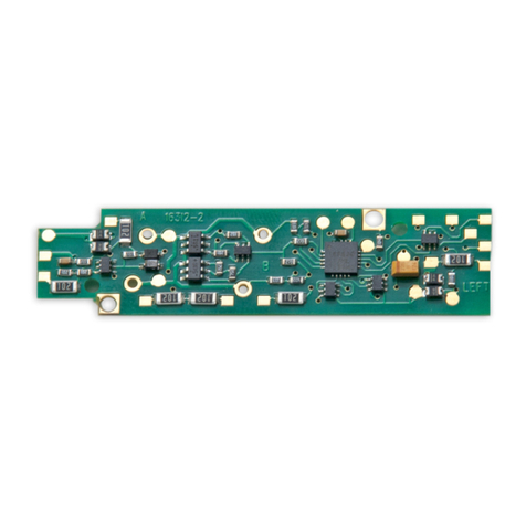
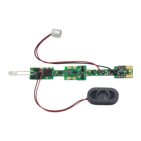
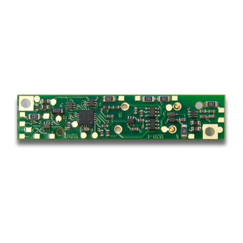
SDH104K1A+FN04K1 COMBO
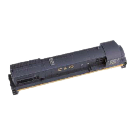
Plug ‘N Play for Kato AC4400 HO Locomotives
Preloaded with AC4400 Sound Scheme
F
Fe
ea
at
tu
ur
re
es
s:
:
nDigitrax SoundFXTM Sound System-Your locomotives will sound like the
real thing with SoundFX
Customizable 8 Bit Sound
3 simultaneous voices
Downloadable Sound with Digitrax PR2 and SoundLoader software
4 Megabit Sound Memory
Playable F2/Whistle with DT400 Throttle
1 Watt Sound Output
Cam input-synchronized steam chuff (yes, you can install in a steam loco)
nSmart Power Management-no more booster or programmer shutdowns! No
extra equipment needed to program or run
nDigitrax LocoMotion®-Proven Complete Train Control technology
Fine Speed control with 128 Speed Steps, Acceleration and Deceleration,
User Settable Normal Direction of Travel, Switching Speed Feature, 3 Step
Speed Tables, 28 Step Speed Tables, Torque Compensation and more
nDigitrax FX3Functions-Control lights and functions
nScalable Speed Stabilization (Back EMF)
nSuperSonic motor drive for silent operation
nPlug ‘N Play design makes installation quick and easy
nTransponder equipped ready for transponding on your layout
nProgram using any Digitrax Compatible Control system without having
to buy any extra equipment
nDirect mode programming
nOperations Mode Programming (Ops Mode Read Back is available on
transponder equipped layouts, too)
nDecoder Reset CV with or without speed table reset
nMotor Isolation Protection helps prevent damage to your decoder
nBasic, Advanced & UniVersal Consisting
n2 Digit and 4 Digit Addressing
nDCC Compatible
©2006 Digitrax, Inc www.digitrax.com 1
C
Co
om
mp
pl
le
et
te
eT
Tr
ra
ai
in
nC
Co
on
nt
tr
ro
ol
l
R
Ru
un
nY
Yo
ou
ur
rT
Tr
ra
ai
in
ns
s,
,N
No
ot
tY
Yo
ou
ur
rT
Tr
ra
ac
ck
k!
!
HO Scale
SDH104K1A: Plug N’ Play Mobile Decoder with SoundFXTM
Includes 28mm 32 Ohm Speaker & 330uF Capacitor
1.0 Amp/1.3 Amps Peak
FN04K1: 4 Function FX3200ma Decoder
©2006 Digitrax, Inc www.digitrax.com 2
P
Pa
ar
rt
ts
sL
Li
is
st
t
1 SDH104K1A Mobile with Sound FXTM 1 Instruction sheet
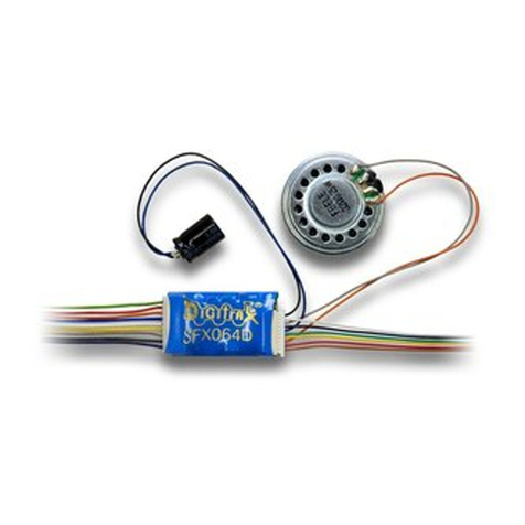
1 Speaker harness with 28mm 32 Ohm speaker and 330 uF capacitor/clip
1 FN04K1 Function Decoder
I
In
ns
st
ta
al
ll
la
at
ti
io
on
nI
In
nf
fo
or
rm
ma
at
ti
io
on
n
See the Digitrax Decoder Manual for complete decoder test procedures, instal-
lation instructions, programming and technical information. Digitrax manuals
and instructions are updated periodically. Please visit www.digitrax.com for the
latest versions, technical updates and additional locomotive-specific installation
instructions.
I
In
ns
st
ta
al
ll
la
at
ti
io
on
nI
In
ns
st
tr
ru
uc
ct
ti
io
on
ns
s
1) Carefully remove the AC4400 couplers, shell, and side-decks as indicated on
manufacturer’s model assembly diagram.
C
Co
om
mp
pl
le
et
te
eT
Tr
ra
ai
in
nC
Co
on
nt
tr
ro
ol
l
R
Ru
un
nY
Yo
ou
ur
rT
Tr
ra
ai
in
ns
s,
,N
No
ot
tY
Yo
ou
ur
rT
Tr
ra
ac
ck
k!
!
Figure 2:
Installation
Wiring Diagram
Warning:
To prevent decoder
damage, be sure
the motor contacts
are properly seated
before applying
power.
Motor
Contacts
Mount
Screws
Track Wires
Speaker
Capacitor Track Wires
SDH104K1A: Motor and Sound Decoder
FN04K1:
Function Decoder
SDH104K1A with FN04K1 Attached For more reliable operation
Digitrax recommends sol-
dering the connections
between the two decoders.
Figure 1: SDH140K1A & FN04K1 Decoders
Light board removed
©2006 Digitrax, Inc www.digitrax.com 3
2) Disconnect 4 track wires from the track power clips on the light board.
Unscrew and remove light board. Retain the two screws.
3) If the FN04K1 is not already attached to the SDH104K1A, plug it in and
solder the pins to secure the two decoders together and clip the two center
pins to prevent shorting to the LED leads. We recommend soldering the
pins in place to ensure a secure electrical connection.
4) Place SDH104K1A decoder in position and use small pliers to press in 2
motor contacts. Using 2 light board screws removed earlier, secure the
decoder in position.
5) Install the speaker by removing the 2 piece diesel tank surround. From the
engineer/right hand side of the locomotive place the 28mm speaker attached
to the wire harness in the speaker enclosure with the cone facing outward.
Remove any magnetic debris from the speaker. Replace diesel tank sur-
round.
6) Replace side-decks and couplers.
7) Re-connect the 4 track wires by inserting them under the track power clips
on the SDH104K1A. Be sure that the wires are retained and do not touch
anything but the clips and pads. Run the track wires in the track lead slots
in the casting so they do not interfere with the shell.
8) Install the capacitor attached to the wire harness at the rear of the casting
using the plastic clip provided. Be sure no wires short to the casting. Trim
back and secure any unused wires so they do not short to the decoder or
frame or bind the drive shafts.
9) Inspect and test the installation before replacing the shell.
2
24
44
43
3T
Tr
ra
an
ns
sm
mi
it
tt
te
er
rR
RD
DT
T8
85
50
0-
-8
87
72
2-
-9
98
89
90
0
P
Pa
an
na
am
ma
aC
Ci
it
ty
y,
,F
Fl
l3
32
24
40
04
4F
F8
85
50
0-
-8
87
72
2-
-9
95
55
57
7
w
ww
ww
w.
.d
di
ig
gi
it
tr
ra
ax
x.
.c
co
om
mE
Es
sa
al
le
es
s@
@d
di
ig
gi
it
tr
ra
ax
x.
.c
co
om
m
Diesel Tank Surround
Speaker Installed Inside
Speaker Enclosure
Figure 3: Speaker Installation Diagram
©2006 Digitrax, Inc www.digitrax.com 4
C
Cu
us
st
to
om
mi
iz
zi
in
ng
gY
Yo
ou
ur
rD
De
ec
co
od
de
er
r
Your Digitrax decoder is ready to run and will operate using address 03 with no
additional programming. On your Digitrax system, simply select the locomo-
tive’s address and the sound will start. On some DCC systems, it is necessary
to select the locomotive address AND send a command to start the sound.
For a more prototypical railroading experience, your decoder can be cus-
tomized for your specific locomotive by programming some of the
Configuration Variables, or CVs, available. Digitrax SD decoders can be pro-
grammed using either the direct method on a programming track or with the
operations mode using the main line. See the Digitrax Decoder Manual or the
Digitrax web site for more information.
Intial Test and Programming: This decoder is preprogrammed and tested
with an AC4400 sound scheme, and is ready to operate on factory default
address 03. Before customizing the decoder it is useful to run it on the fac-
tory default address 03 to check the installation. The following sections
show how to change the locomotive address and customize the decoder
For more information on decoder installation and programming techniques and
examples visit the www.digitrax.com
C
Ch
ha
an
ng
gi
in
ng
gt
th
he
eD
De
ec
co
od
de
er
rA
Ad
dd
dr
re
es
ss
s
The first CV most people change is the decoders address. This lets you inde-
pendently control each loco with its own unique address. Digitrax decoders are
C
Co
om
mp
pl
le
et
te
eT
Tr
ra
ai
in
nC
Co
on
nt
tr
ro
ol
l
R
Ru
un
nY
Yo
ou
ur
rT
Tr
ra
ai
in
ns
s,
,N
No
ot
tY
Yo
ou
ur
rT
Tr
ra
ac
ck
k!
!
Track Power Clips
Capacitor with
Clip Installed
Track Lead Slots
Track Power Clip Detail
Figure 4: Installation Diagram
©2006 Digitrax, Inc www.digitrax.com 5
shipped with CV01 (AD2), the two digit address, set to 03. Following is a brief
description of how to change the decoder address with a Digitrax DT series
throttle. See your Starter Set Manual for complete programming instructions.
1. Place the loco on the programming track or on the main line.
2. Enter the programming mode using your DCC system/throttle. On DT400
press PROG until you see “Pd” if using a programming track or “Po” if
using the main line.
3. Use your throttle to choose the address you want to set up for the decoder.
On the DT400 use the left knob to dial AD2 for two digit programming, use
the right knob to dial up the address, click the right knob to change to AD4
for programming 4 digit addresses.
4. Complete address programming. On DT400 press ENTER. Note: CV29
must also be programmed to enable 4 digit addressing, this is done automat-
ically by the DT300 & DT400 but not on earlier throttles.
U
Us
si
in
ng
gt
th
hi
is
sd
de
ec
co
od
de
er
ri
in
no
ot
th
he
er
rl
lo
oc
co
om
mo
ot
ti
iv
ve
es
s
The sound project loaded into this decoder is for an AC4400 diesel locomotive.
If you want to install it in a different locomotive, you can simply load a dif-
ferent sound project for that type of locomotive. The cam input is available
for steam installations where you want to synchronize chuffing.
D
Di
ig
gi
it
tr
ra
ax
xL
Lo
oc
co
oM
Mo
ot
ti
io
on
n
®
S
Sy
ys
st
te
em
m
Your locomotives look like the real thing, now you can make them run like the
real thing, too. Digitrax decoders incorporate torque compensation for smooth
as silk operation. You can also program CVs that control momentum, 3 step
and 128 step speed tables, switching speed, normal direction of travel,
scaleable speed stabilization and more to take full advantage of the Digitrax
LocoMotion System.
M
Mo
om
me
en
nt
tu
um
m-
-C
CV
V0
03
3&
&C
CV
V0
04
4
Momentum is part of the LocoMotion System. Acceleration is controlled by
CV03 and deceleration by CV04. Both come from the factory set to 000/x00. A
range of 000/x00 to 031/x1F is available for both accel and decel. We recom-
mend that you try CV03:003/x03 and CV04:000/x00 as a starting point for
experimenting with momentum.
S
Sp
pe
ee
ed
dT
Ta
ab
bl
le
es
s-
-H
Ho
ow
wt
th
he
eL
Lo
oc
co
oR
Re
es
sp
po
on
nd
ds
st
to
ot
th
he
eT
Th
hr
ro
ot
tt
tl
le
e
With Digitrax LocoMotion, there are two types of speed tables: 3 Step Tables
and High Resolution 28 Step Tables. Please see your Digitrax Decoder Manual
for a discussion of the 28 Step Tables. The 3 Step Tables are set up by program-
ming 3 CVs: Start Voltage (CV02), Mid point Voltage (CV06) and Max Voltage
(CV05). These values are set at 000/x00 at the factory. All have a range of val-
2
24
44
43
3T
Tr
ra
an
ns
sm
mi
it
tt
te
er
rR
RD
DT
T8
85
50
0-
-8
87
72
2-
-9
98
89
90
0
P
Pa
an
na
am
ma
aC
Ci
it
ty
y,
,F
Fl
l3
32
24
40
04
4F
F8
85
50
0-
-8
87
72
2-
-9
95
55
57
7
w
ww
ww
w.
.d
di
ig
gi
it
tr
ra
ax
x.
.c
co
om
mE
Es
sa
al
le
es
s@
@d
di
ig
gi
it
tr
ra
ax
x.
.c
co
om
m
©2006 Digitrax, Inc www.digitrax.com 6
ues from 000/x00 to 255/xFF. We recommend the following CV values as a
starting point for experimenting with speed tables.
O
Ot
th
he
er
rL
Lo
oc
co
oM
Mo
ot
ti
io
on
n
®
F
Fe
ea
at
tu
ur
re
es
s:
:S
Sw
wi
it
tc
ch
hi
in
ng
gS
Sp
pe
ee
ed
d,
,N
No
or
rm
ma
al
lD
Di
ir
re
ec
ct
ti
io
on
no
of
f
T
Tr
ra
av
ve
el
l&
&S
Sc
ca
al
le
ea
ab
bl
le
eS
Sp
pe
ee
ed
dS
St
ta
ab
bi
il
li
iz
za
at
ti
io
on
n(
(B
Ba
ac
ck
kE
EM
MF
F)
)F
Fe
ea
at
tu
ur
re
es
s
Switching speed is controlled by CV54. The factory setting is 000/x00 for
OFF. To turn on the switching speed feature, program CV54 to a value of
001/x01. When this feature is on, use F6 to activate and deactivate switching
speed. When switching speed is ON and F6 is ON, the switching speed feature
is on. With the feature on the throttle’s target speed is effectively reduced by
about 50% and the effects of accel and decel programmed into the decoder are
reduced by 1/4. This is useful for yard switching operations.
Normal Direction of Travel is controlled by CV29. See your decoder manual
for additional information on the settings for CV29.
Scaleable Speed Stabilization (Back EMF) intensity, or droop, is controlled
by CV57. The factory setting for this feature is 006/x06 which is suitable for
most locos. You can adjust this value in the range of 000/x00 for OFF to
015/x0F for the maximum effect. Consult your Digitrax Decoder Manual for
info about CVs 55 & 56 and their effects on scaleable speed stabilization. The
factory setting for both CV55 & CV56 is 000/x00.
S
Su
up
pe
er
rS
So
on
ni
ic
cS
Si
il
le
en
nt
tO
Op
pe
er
ra
at
ti
io
on
na
an
nd
dT
To
or
rq
qu
ue
eC
Co
om
mp
pe
en
ns
sa
at
ti
io
on
n
The factory settings in the decoder provide silent, smooth operation of your
locomotive under most conditions. For more information about these settings,
please see the Digitrax Decoder Manual or our website.
D
Di
ig
gi
it
tr
ra
ax
xT
Tr
ra
an
ns
sp
po
on
nd
di
in
ng
gC
CV
V6
61
1
Digitrax Transponding is controlled by CV61. The initial factory set value is
000/x00 for OFF. To turn on transponding, program CV61 to a value of
002/x02. This allows you to use Digitrax transponding to keep track of your
C
Co
om
mp
pl
le
et
te
eT
Tr
ra
ai
in
nC
Co
on
nt
tr
ro
ol
l
R
Ru
un
nY
Yo
ou
ur
rT
Tr
ra
ai
in
ns
s,
,N
No
ot
tY
Yo
ou
ur
rT
Tr
ra
ac
ck
k!
!
Loco Type V Start V Mid V Max
CV02 CV06 CV05
Switcher
Concentrated low speed. Limited top 002/x02 038/x26 064/x50
speed
Road Switcher
Prototypical top speed w/evenly 002/x02 048/x30 098/x62
distributed curve from 0 to top speed
Mainline Loco
Quick increase to cruising speed then 002/x02 128/x80 154/x9A
levels off to prototypical top speed.
©2006 Digitrax, Inc www.digitrax.com 7
rolling stock. When transponding is enabled, the front light of the locomotive
may flicker slightly to indicate transponding signal is being communicated. For
optimal transponding operation, we recommend that you hook up the forward
and rear lights as shown above.
D
De
ec
co
od
de
er
rR
Re
es
se
et
tC
CV
V0
08
8
Decoder reset lets you reset all CV values to the initial factory settings. To
reset all CV values, program CV08 to a value of 008/x08. You also have the
option of resetting all values except the 28 speed step tables. To do this,
program CV08 to a value of 009/x09.
D
Di
ig
gi
it
tr
ra
ax
xS
So
ou
un
nd
dF
FX
XT
TM
MS
Sy
ys
st
te
em
m
Digitrax SoundFXTM lets you make your locos sound like the real thing!
The SoundFX sound CVs in the range of CV140 to CV256 let you customize
your decoder without having to reprogram or change the installed sound
scheme.
Standard decoder CVs in the range of CV01 to CV120 operate the same as for
a non-sound FX3Digitrax decoders (they control motor and light functions
etc.) CV58 is used as Master Volume, and CV60 is used to select an alter-
nate scheme, if provided in the sound project.
Sound CV155 is provided to select Diesel engine “notching” modes. The
default of CV155= 00 provides “automatic notching” that changes the
diesel RPM settings at 8 distinct throttle speeds that are controlled by Sound
CV132.
Sound CV155=01 selects “semi-automatic notching” mode that allows F6 ON
to increase the notch from the current throttle setting and F7 ON to decrease
back towards the lowest current throttle notch setting.
Sound CV155=02 selects “manual notching” mode that allows F6 ON to
increase the notch setting and F7 ON to decrease the notch setting irrespec-
tive of the throttle setting, which controls just the motor speed.
The decoder’s sound scheme can be reloaded using a Digitrax PR2 program-
mer and a sound project file (for example AC4400.spj) from the Digitrax
Sound Depot web site. Typical sound downloads take between 50 and 100
seconds depending on the project complexity and file size.
The following tables show the CVs used in this decoder version and how it is
set up at the factory to operate various sounds using your throttle.
2
24
44
43
3T
Tr
ra
an
ns
sm
mi
it
tt
te
er
rR
RD
DT
T8
85
50
0-
-8
87
72
2-
-9
98
89
90
0
P
Pa
an
na
am
ma
aC
Ci
it
ty
y,
,F
Fl
l3
32
24
40
04
4F
F8
85
50
0-
-8
87
72
2-
-9
95
55
57
7
w
ww
ww
w.
.d
di
ig
gi
it
tr
ra
ax
x.
.c
co
om
mE
Es
sa
al
le
es
s@
@d
di
ig
gi
it
tr
ra
ax
x.
.c
co
om
m
©2006 Digitrax, Inc www.digitrax.com 8
C
Co
om
mp
pl
le
et
te
eT
Tr
ra
ai
in
nC
Co
on
nt
tr
ro
ol
l
R
Ru
un
nY
Yo
ou
ur
rT
Tr
ra
ai
in
ns
s,
,N
No
ot
tY
Yo
ou
ur
rT
Tr
ra
ac
ck
k!
!
CV#
Used For
Factory
defaultValue
01
2 Digit Address
03
11
Sound Time Out, 06=Sound ends when
loco address is de-selected, 00=Sound
stays on after loco is de-selected
06
29
Configuration Register
06
49
Forward Light (F0F)-Headlight
0
50
Reverse Light (F0R)-Reverse Light
0
51
Function 1
0
52
Function 2
0
58
Master Volume Control
0
60
Select Sound Scheme
0
132
Notch Rate
127
135
Mute Volume
0
140
Prime Mover Volume (Min=0, max=64)
60
141
Bell Volume (Min=0, max=64)
25
142
Horn/Whistle Volume (Min=0, max=64)
60
143
Time-Scattered Air Effects Volume
(Min=0, max=64)
30
146
Bell Ring Rate
07
147
Air Drier Rate
02
148
Compressor Run Rate
30
149
Air Compressor On Time
20
150
Horn/Whistle Setup (Default=0, Playable
Horn=1, Alternate Horn=2)
0
151
Auto Coupler Sequence Threshold Value-
Peak speed to allow auto coupler/brake
when direction change occurs and F3 is
ON
48
152
Project Author ID, Digitrax=221
221
153
Sound Project ID, AC4400=02
02
155
Notching Mode: 00=Automatic, 01=Semi-
Automatic, 02=Manual
00
For additional information about sound CVs visit www.digitrax.com/soundcvs
©2006 Digitrax, Inc www.digitrax.com 9
F
Fu
un
nc
ct
ti
io
on
nC
Co
on
nt
tr
ro
ol
lU
Us
si
in
ng
gt
th
he
eF
FN
N0
04
4F
Fu
un
nc
ct
ti
io
on
nD
De
ec
co
od
de
er
r
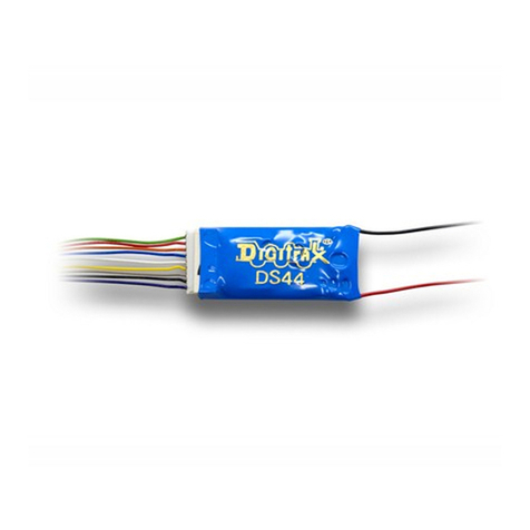
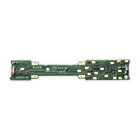
The SDH104K1A has no native function control ability. The FN04K1 and other
Digitrax function decoders can be used in conjunction with the sound and
motor decoder if function control is to be used. The LEDs on the SDH104K1A
will not work unless a separate function decoder is installed.
2
24
44
43
3T
Tr
ra
an
ns
sm
mi
it
tt
te
er
rR
RD
DT
T8
85
50
0-
-8
87
72
2-
-9
98
89
90
0
P
Pa
an
na
am
ma
aC
Ci
it
ty
y,
,F
Fl
l3
32
24
40
04
4F
F8
85
50
0-
-8
87
72
2-
-9
95
55
57
7
w
ww
ww
w.
.d
di
ig
gi
it
tr
ra
ax
x.
.c
co
om
mE
Es
sa
al
le
es
s@
@d
di
ig
gi
it
tr
ra
ax
x.
.c
co
om
m
Func
Used For
Notes
F0
Lights
F1
Bell
F2
Horn/Whistle
CV150 sets mode
F3
Coupler crash
Auto coupler/brake set by
CV151 max speed
F4
Air feature disable
F4 off means pop-off and
drier are enabled
F5
Dynamic Brake
Fans
F6
Air blowoff
Notch UP if CV155=01 or
02
F7
Crossing Gate
Airhorn Sequence
Notch DOWN, if
CV155=01 or 02
F8
Mute Control
F8 ON is mute
F9
Brake squeal
F10
Crossing Gate
Airhorn Sequence
Right Hand Track
F0-Forward (White)
Left Hand Track
Figure 5: FN04K1 Function Decoder Outputs
F0R-Reverse (Yellow)
+Common (Blue)
+Common (Blue)
F2-Function 2 (Violet)
F1-Function 1 (Green)
©2006 Digitrax, Inc www.digitrax.com 10
FN04K1 is set up to control the forward and reverse lights on the locomotive
through the white lead and yellow lead using Function 0 (F0F-forward and
F0R-reverse) for directional lighting. Functions F1(Green) and F2(Violet) are
available on the FN04. To use these functions, solder a wire from the pad for
the function you wish to use to the lamp (or other device) you wish to control.
The Blue/+Common pad works the same way as the blue wire on the harness
and is provided here for convenience. The wire colors indicated are the stan-
dard industry color code (you can use any color you like). These colors are
important if you plan to use function remapping.
CAUTION: When adding function wires, be very careful that the wires you add
do not come into contact with any other pads or components on the board
where they might create a short circuit.
All four function outputs can be set up with Digitrax FX3lighting effects or as
standard on/off functions with the following operational qualifiers:
1. Forward or Reverse direction of travel, or
2. Whether F0 is on or off, or
3. Both direction of travel and whether F0 is on or off, or
4. Whether the locomotive is stopped or moving.
F
Fu
un
nc
ct
ti
io
on
nR
Re
em
ma
ap
pp
pi
in
ng
g
Function remapping allows you to program the function outputs of your decoder
to be controlled by selected function keys on your throttle. Please consult the
Digitrax Decoder Manual or website for information on function remapping.
M
Ma
as
st
te
er
rL
Li
ig
gh
ht
tS
Sw
wi
it
tc
ch
h
Each of the four function outputs can be programmed to turn on and off with
the F0 ON/OFF key on your throttle, creating a Master Light Switch. The CV
values for creating this effect are listed in the Digitrax Decoder Manual in the
section: Setting up FX & FX3Effects On Function Outputs.plugs into the
decoder. This 9 pin connector has been adopted by other companies in the DCC
industry, too.
S
So
ou
un
nd
dF
FX
XD
DC
CO
Op
pe
er
ra
at
ti
io
on
nM
Mo
od
de
e
Digitrax SoundFX deccoders will operate on smooth DC power. The sound will
not start until approximately 5 volts is applied to the track and there will be no
“start up sound.”
S
So
ou
un
nd
dF
FX
XT
Tr
ro
ou
ub
bl
le
es
sh
ho
oo
ot
ti
in
ng
g
If the sound does not start in the decoder
1. Make sure you have selected the locomotive on a throttle. The sound will
not run unless the locomotive is addressed in the system.
C
Co
om
mp
pl
le
et
te
eT
Tr
ra
ai
in
nC
Co
on
nt
tr
ro
ol
l
R
Ru
un
nY
Yo
ou
ur
rT
Tr
ra
ai
in
ns
s,
,N
No
ot
tY
Yo
ou
ur
rT
Tr
ra
ac
ck
k!
!
©2006 Digitrax, Inc www.digitrax.com 11
2. Check your installation to make sure the decoders are installed properly.
If the sound output sounds distorted
1. Check the speaker cone for magnetic debris that may have collected there.
Debris on the speaker will cause a loss of sound quality and must be removed.
2. Be sure that the CV58 volume is not set at a level that is too high for the
speaker. For impedances below 32ohms (e.g. 8 to 30 ohms) set the volume set-
ting lower to ensure the 1 watt output rating is not exceeded.
If the LEDs do not respond to F0:
1. Be sure the locomotive address you are using to send the command is actu-
ally the address programmed into the decoder.
2. Make sure you have good electrical connections between the FN04K1 to the
SDH104K1A. We recommend soldering these connections for best reliability.
If the sound in your decoder shuts down after you stop it and you are not
using a Digitrax system for control. On some DCC systems decoders are not
addressed by DCC packets after the locomotive is set to 0 speed. In this case
after the CV11 timeout elapses (6 second default), sound will “shutdown.”. To
defeat this feature, set CV11=00 to remove the timeout and shutdown. To make
sounds, the decoder must have a command addressed to it at least once.
If you have trouble reading back on the programming track, this may be
due to your system using Direct Bit mode for Service Mode readback. This cre-
ates difficulty reading two decoders in a locomotive that may have different
data or responses. Since the SDH104K1A and FN04 are actually two decoders,
you’ll need to use standard direct mode for reading back CV values on the pro-
gramming track. Of course you can always just re-program the CV value into a
CV to get the desired results. OPs mode is recommended for programming all
CVs except CV01, CV17 & CV18 (2 digit and 4 digit addresses).
W
Wa
ar
rr
ra
an
nt
ty
y&
&R
Re
ep
pa
ai
ir
r
All warranties on Digitrax products are limited to refund of purchase price,
repair or replacement at Digitrax’s sole discretion. Except as expressly stated in
the full warranty statement, there are no warranties, express or implied, includ-
ing but not limited to any warranties of merchantability or fitness for a particu-
lar purpose. For complete warranty details see www.digitrax.com.
Damaged decoders should be returned directly to Digitrax for repair.
Incorporates elements of US Patents 6220552, 6545886, 6729584, 6747579,
other patents pending.
Digitrax, Inc. is not responsible for unintentional
errors or omissions in this document.
2
24
44
43
3T
Tr
ra
an
ns
sm
mi
it
tt
te
er
rR
RD
DT
T8
85
50
0-
-8
87
72
2-
-9
98
89
90
0
P
Pa
an
na
am
ma
aC
Ci
it
ty
y,
,F
Fl
l3
32
24
40
04
4F
F8
85
50
0-
-8
87
72
2-
-9
95
55
57
7
w
ww
ww
w.
.d
di
ig
gi
it
tr
ra
ax
x.
.c
co
om
mE
Es
sa
al
le
es
s@
@d
di
ig
gi
it
tr
ra
ax
x.
.c
co
om
m
Made in U.S.A.
307-SDH104K1AC 1k/12/08
SDH104K1A+FN04K1 Combo
Plug ‘N Play Sound/Mobile Decoder + Function Decoder
for Kato HO AC4400
2443 Transmitter Road
Panama City, FL 32404
www.digitrax.com
T850-872-9890
F850-872-9557
E[email protected]

This manual suits for next models

1

Other Digitrax Media Converter manuals

Digitrax DH163IP User manual

Digitrax

Digitrax DH163IP User manual

Digitrax DN163I1C User manual

Digitrax

Digitrax DN163I1C User manual

Digitrax DN163A2 User manual

Digitrax

Digitrax DN163A2 User manual

Digitrax DH166MT User manual

Digitrax

Digitrax DH166MT User manual

Digitrax DH165K1A User manual

Digitrax

Digitrax DH165K1A User manual

Digitrax DZ123M0 User manual

Digitrax

Digitrax DZ123M0 User manual

Digitrax DZ123MK1 User manual

Digitrax

Digitrax DZ123MK1 User manual

Digitrax 3 Series User manual

Digitrax

Digitrax 3 Series User manual

Digitrax DN163I1B User manual

Digitrax

Digitrax DN163I1B User manual

Digitrax SE74 User manual

Digitrax

Digitrax SE74 User manual

Digitrax DN126M2 User manual

Digitrax

Digitrax DN126M2 User manual

Digitrax SoundFX SFX064D User manual

Digitrax

Digitrax SoundFX SFX064D User manual

Digitrax SoundFX SFX0416 User manual

Digitrax

Digitrax SoundFX SFX0416 User manual

Digitrax DN121PS User manual

Digitrax

Digitrax DN121PS User manual

Digitrax DZ125 User manual

Digitrax

Digitrax DZ125 User manual

Digitrax SDN144K1E User manual

Digitrax

Digitrax SDN144K1E User manual

Digitrax DN163K1a User manual

Digitrax

Digitrax DN163K1a User manual

Digitrax DN163A1 User manual

Digitrax

Digitrax DN163A1 User manual

Digitrax PR3 XtRa User manual

Digitrax

Digitrax PR3 XtRa User manual

Digitrax DH123PS User manual

Digitrax

Digitrax DH123PS User manual

Digitrax DN163PS User manual

Digitrax

Digitrax DN163PS User manual

Digitrax DH166P User manual

Digitrax

Digitrax DH166P User manual

Digitrax SE8C User manual

Digitrax

Digitrax SE8C User manual

Digitrax DN166I1D User manual

Digitrax

Digitrax DN166I1D User manual

Popular Media Converter manuals by other brands

marklin 60905 user guide

marklin

marklin 60905 user guide

AxelTech Falcon Series user manual

AxelTech

AxelTech Falcon Series user manual

M-system M8VS instruction manual

M-system

M-system M8VS instruction manual

LH Technologies LH 500 Operator's manual

LH Technologies

LH Technologies LH 500 Operator's manual

evertz 7700 Series manual

evertz

evertz 7700 Series manual

UTEPO MC2-FS user manual

UTEPO

UTEPO MC2-FS user manual

Matrox Maevex 6152 Series user guide

Matrox

Matrox Maevex 6152 Series user guide

Cypress CP-1262HE Operation manual

Cypress

Cypress CP-1262HE Operation manual

PXM PX724 user manual

PXM

PXM PX724 user manual

Monoprice 10251 manual

Monoprice

Monoprice 10251 manual

Belkin AV360 Quick install guide

Belkin

Belkin AV360 Quick install guide

AXIOMATIC UMAX030440 user manual

AXIOMATIC

AXIOMATIC UMAX030440 user manual

Armstrong IVS 102 Installation and operating instructions

Armstrong

Armstrong IVS 102 Installation and operating instructions

GRASS VALLEY Sonata Series Planning and installation manual

GRASS VALLEY

GRASS VALLEY Sonata Series Planning and installation manual

YASKAWA PG-F3 installation manual

YASKAWA

YASKAWA PG-F3 installation manual

ADS Technologies PTV-337-EF Help guide

ADS Technologies

ADS Technologies PTV-337-EF Help guide

MA lighting Mini-Midi-Converter user manual

MA lighting

MA lighting Mini-Midi-Converter user manual

Gilson SP-245 operating manual

Gilson

Gilson SP-245 operating manual

manuals.online logo
manuals.online logoBrands
  • About & Mission
  • Contact us
  • Privacy Policy
  • Terms and Conditions

Copyright 2025 Manuals.Online. All Rights Reserved.