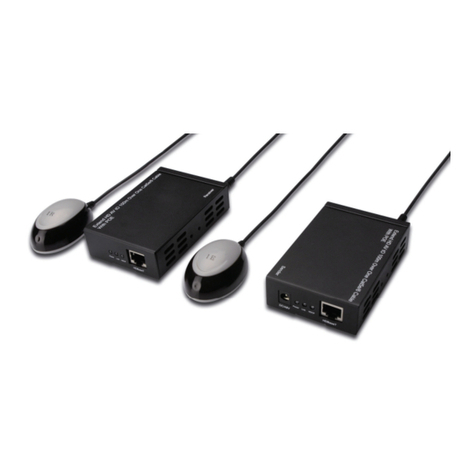
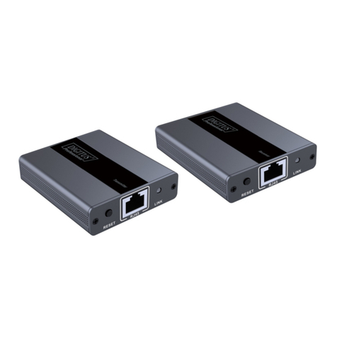
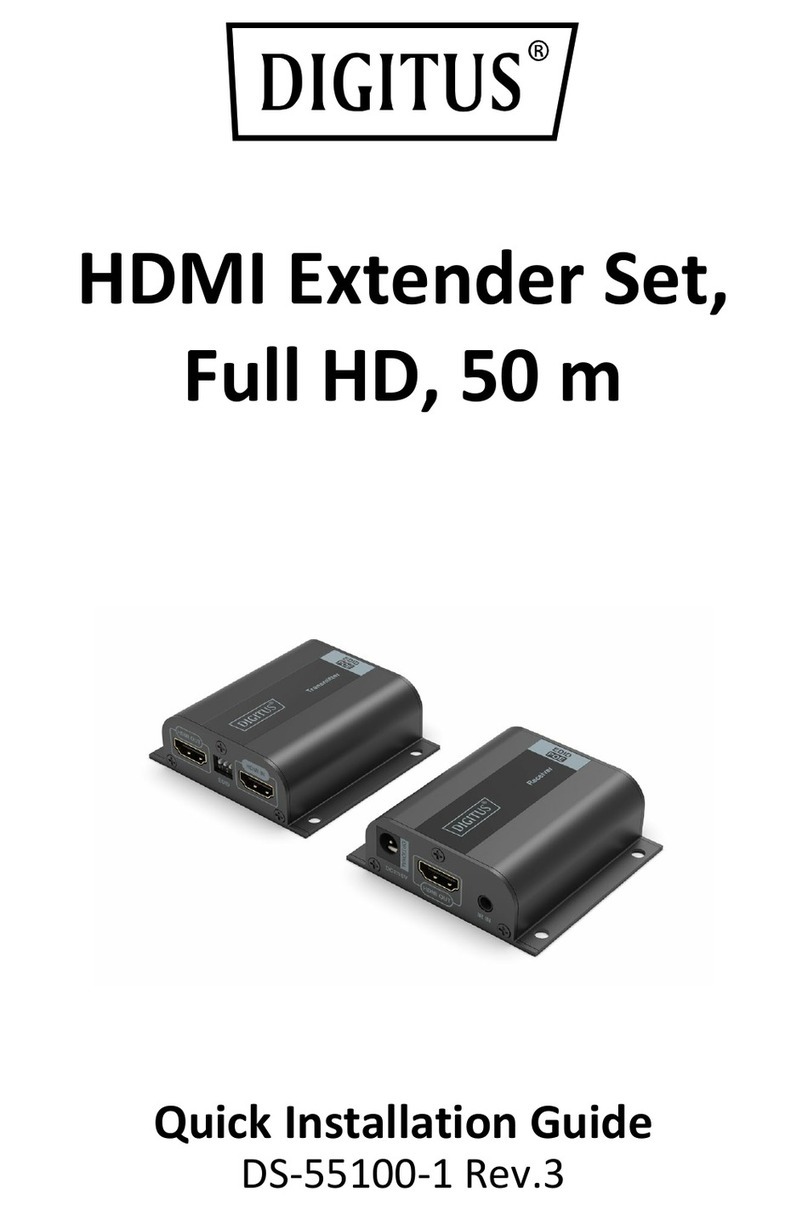
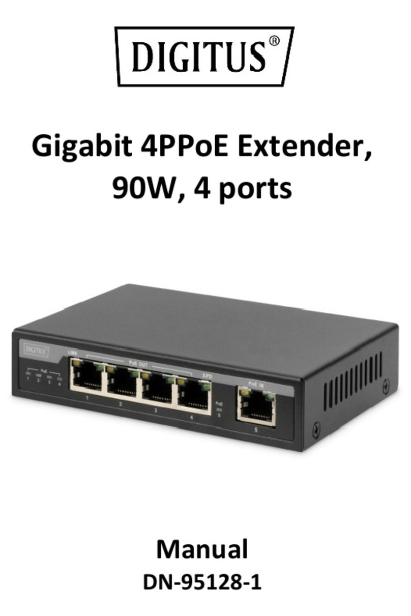
Digitus DS-55129 User manual
Other Digitus Extender manuals

Digitus
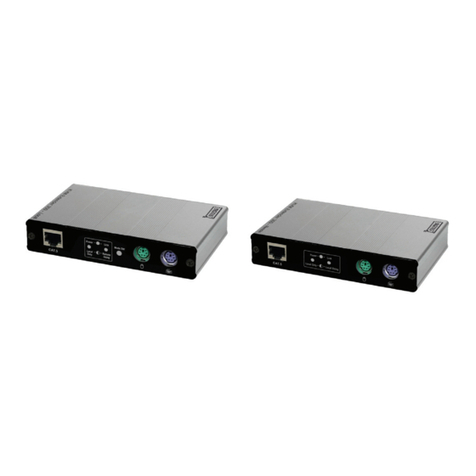
Digitus DS-55126 User manual
Digitus
Digitus DC-51101-LOCAL User manual
Digitus
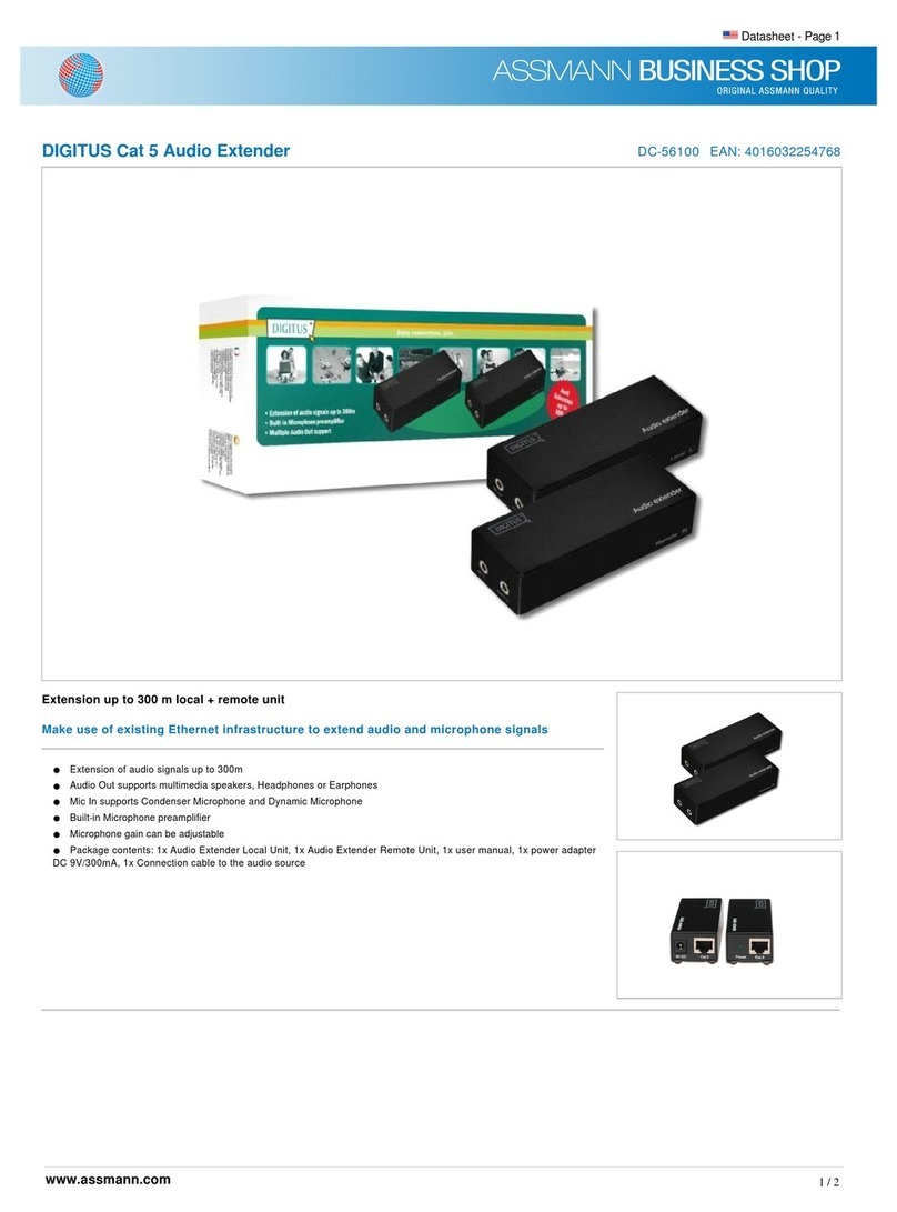
Digitus DC-56100 User manual
Digitus
Digitus DN-95127-1 User manual

Digitus
Digitus DN-95126 User manual
Digitus
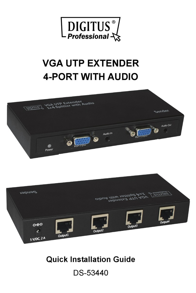
Digitus DS-53440 User manual
Digitus
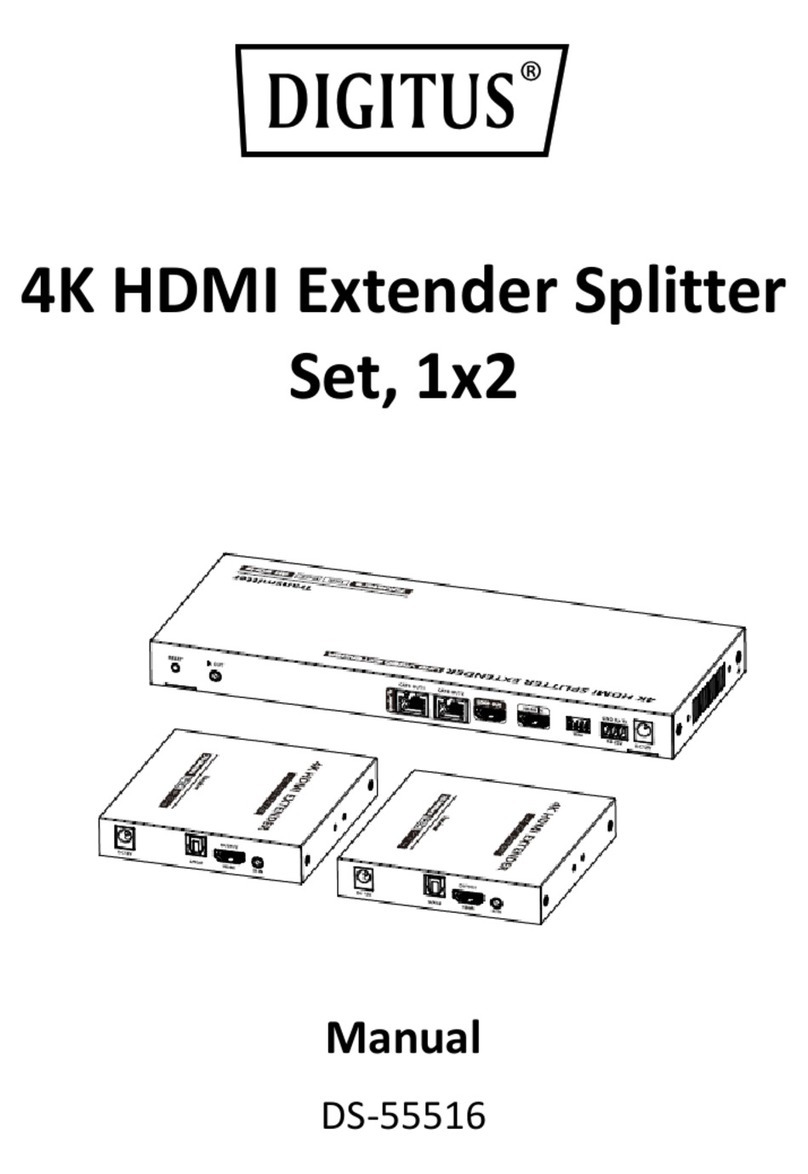
Digitus DS-55516 User manual
Digitus
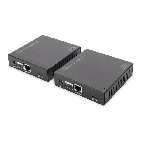
Digitus DS-55502 User manual
Digitus
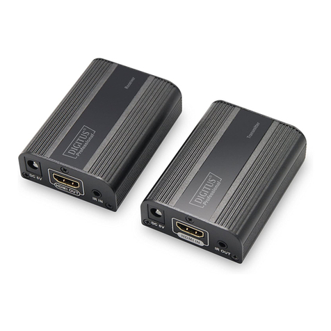
Digitus DS-55204 User manual
Digitus
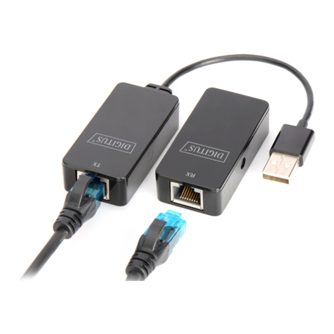
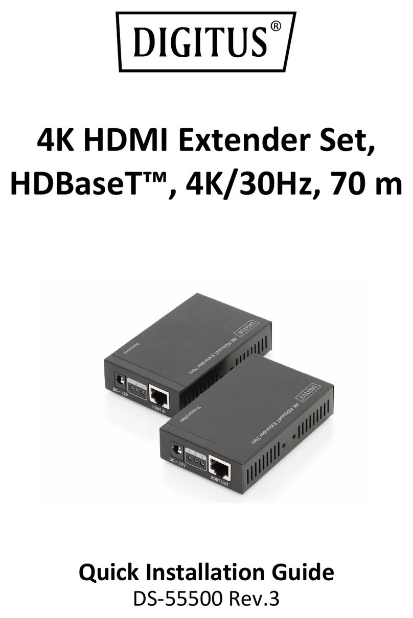
Digitus DA-70141 User manual
Digitus
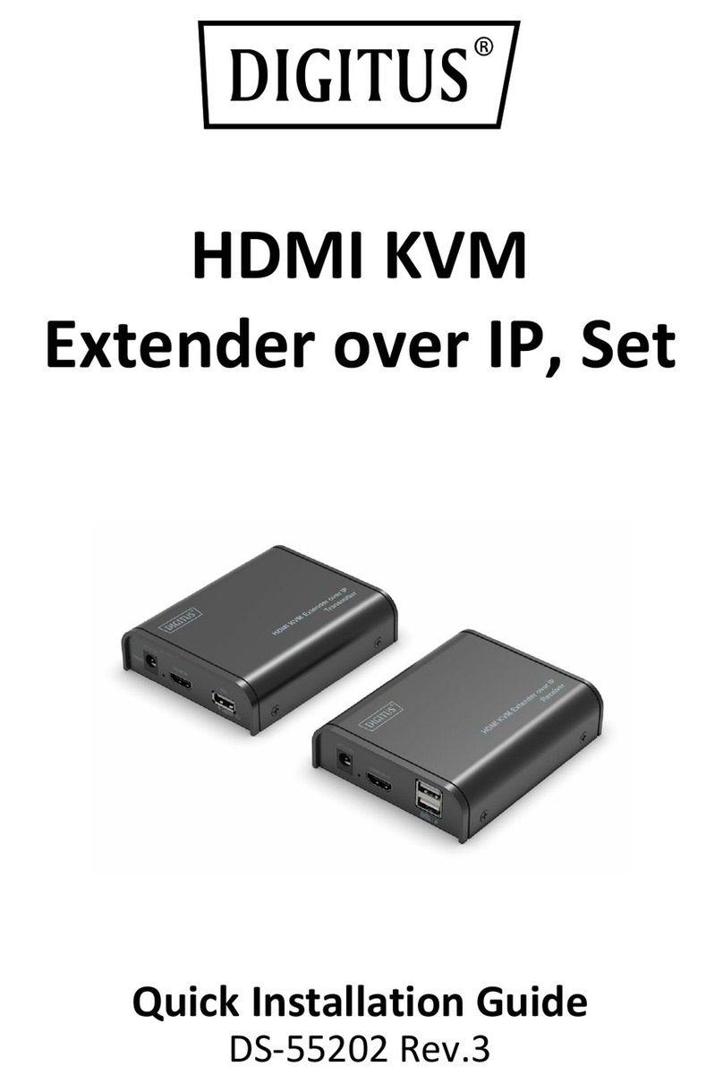
Digitus DS-55500 User manual
Digitus
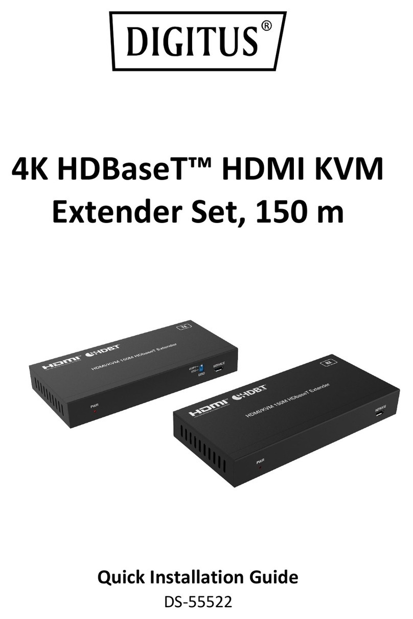
Digitus DS-55202 User manual
Digitus
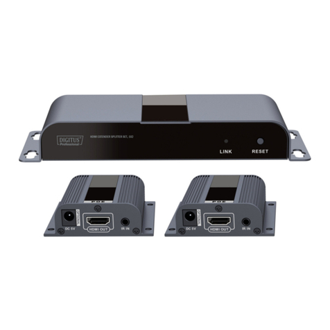
Digitus DS-55522 User manual
Digitus
Digitus DS-55302 User manual
Digitus
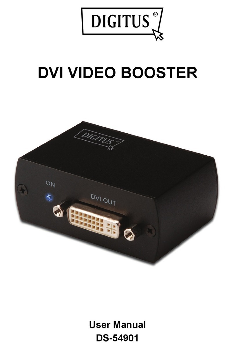
Digitus DS-54901 User manual
Digitus
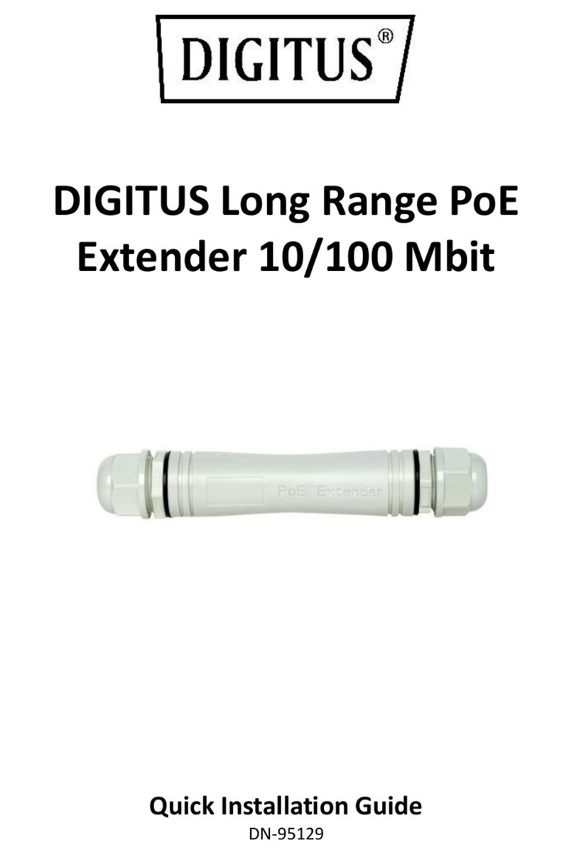
Digitus DN-95129 User manual

Digitus
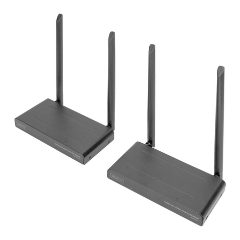
Digitus DN-95123 User manual
Digitus
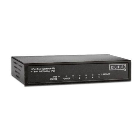
Digitus DS-55321 User manual
Digitus
Digitus DN-95121 User manual
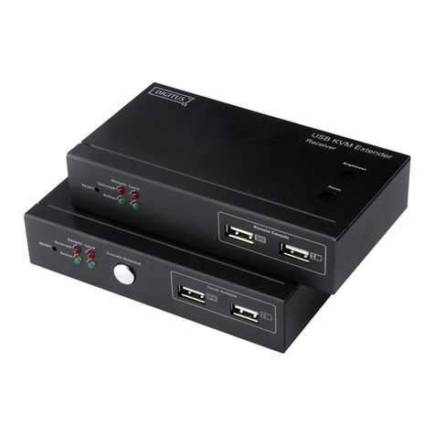
Digitus
Digitus OVER CAT.5 User manual
Popular Extender manuals by other brands

foxunhd
foxunhd SX-AEX01 operating instructions

TERK Technologies
TERK Technologies LFIRX2 owner's manual

Devolo
Devolo Audio Extender supplementary guide

Edimax
Edimax EW-7438RPn V2 instructions

Shinybow USA
Shinybow USA SB-6335T5 instruction manual

SECO-LARM
SECO-LARM ENFORCER EVT-PB1-V1TGQ installation manual
