Dikai DK-D03S User manual

DK-D03S V2.3版本

OPERATIONAL MANUAL
- 2- D03S THERMAL TRANSFER OVERPRINTER
NOTICE
Thank you for choosing DIKAI to provide printing solutions.
DIKAI is a top manufacturer of coding machines & coding consumables in China, established in 1995,
products include:
Thermal Transfer Overprinter
Ink Roll Coder
Hot Stamp Coder
Case & Carton Coder
Thermal Transfer Ribbon
Hot Ink Roll
Hot Stamping Foil
Brass/Steel/Rubber Types
If you have questions or comments, or any information wanted, please visit our website at
www.dikaiproducts.net
Before using this printer, please read and fully comply with these instructions.
Version Clarification
Part NO. Y03S05014EN
Update Date
Manual Version
Revision Department
Description
2017/08/08
V1.1
Technology
Department
Stop
2017/12/29
V2.0
Technology
Department
Stop
2018/06/29
V2.1
Technology
Department
Stop
2019/3/26
V2.2
Technology
Department
Stop
2019/9/20
V2.3
Technology
Department
Officially Published
Version

OPERATIONAL MANUAL
D03S THERMAL TRANSFER OVERPRINTER - 3 -
CONTENTS
1. GENERAL & SAFETY INFORMATION .................................................................................................- 4 -
1.1 GENERAL ...........................................................................................................................................- 4 -
1.2 INTRODUCTION.................................................................................................................................- 4 -
1.3 LABEL ................................................................................................................................................- 5 -
1.4 PARAMETER ......................................................................................................................................- 7 -
2. SAFETY ..............................................................................................................................................- 8 -
2.1 OPERATION GUIDELINES ...................................................................................................................- 8 -
2.2 APPLICATION AND ABUSING.............................................................................................................- 9 -
3. INSTALLATION.................................................................................................................................- 10 -
3.1 COMPONENTS.................................................................................................................................- 10 -
3.2 INSTALLATION REQUIREMENTS ......................................................................................................- 11 -
3.3 STANDARD BRACKETS .....................................................................................................................- 11 -
3.4 INSTALLATION OF THE MOUNTING BRACKET .................................................................................- 13 -
3.5 INSTALLING THE CONTROLLER........................................................................................................- 15 -
3.6 CONTROLLER CONNECTION POINTS...............................................................................................- 15 -
3.7 PRINTER CONNECTORS ...................................................................................................................- 17 -
3.8 PRINT SIGNAL..................................................................................................................................- 20 -
3.9 I/O CABLE CONNECTION .................................................................................................................- 20 -
3.10 INSTALLATION DIMENSION .........................................................................................................- 23 -
4. OPERATION.....................................................................................................................................- 26 -
4.1 START THE PRINTER ........................................................................................................................- 26 -
4.2 HOME PAGE ....................................................................................................................................- 27 -
4.3 SCREEN ICONS.................................................................................................................................- 29 -
4.4 START/ STOP THE PRINTER..............................................................................................................- 41 -
4.5 FILE MANAGEMENT ........................................................................................................................- 42 -
4.6 PARAMETER SETTING......................................................................................................................- 46 -
4.7 UPGRADING THE CONTROLLER BOX ...............................................................................................- 63 -
4.8 REMOVING THE CASSETTE..............................................................................................................- 65 -
4.9 LOADING OR REPLACING THE RIBBON ...........................................................................................- 65 -
4.10 TEST THE CURRENT PRINT JOB....................................................................................................- 69 -
5. MAINTENANCE................................................................................................................................- 70 -
5.1 CLEANING AND CARE.......................................................................................................................- 70 -
5.2 MAINTENANCE SCHEME.................................................................................................................- 71 -
5.3 REPLACING THE PRINTHEAD............................................................................................................- 74 -
5.4 REPLACING THE REEL ROLLER..........................................................................................................- 75 -
6. TROUBLE SHOOTING .......................................................................................................................- 76 -
7. SCHEMATICS AND PARTS ILLUSTRATIONS ......................................................................................- 78 -
7.1 CONTROLLER BOX ............................................................................................................................- 78 -
7.2 CASSETTE ASSEMBLY........................................................................................................................- 79 -
7.3 PRINTER UNIT .................................................................................................................................- 82 -
7.4 OTHER SPARES .................................................................................................................................- 87 -
7.5 RECOMMENDED SPARES .................................................................................................................- 88 -
8. CONSUMABLES INTRODUCTION.....................................................................................................- 89 -

OPERATIONAL MANUAL
- 4- D03S THERMAL TRANSFER OVERPRINTER
1. GENERAL & SAFETY INFORMATION
1.1 GENERAL
This Manual aims to explain how to safely install, operate and maintain D03S Thermal Transfer
Overprinter.
1. Reproduction of any or part of this manual in any form whatsoever without the expressed written
permission of DIKAI is forbidden. The contents of this manual are subject to revision without notice.
2. The use of non genuine DIKAI consumables and spare parts may adversely affect the performance of the
product and could invalidate the warranty.
3. All efforts have been made to ensure the accuracy of the contents of this manual. However, should any
errors be detected, DIKAI would greatly appreciate being notified.
4. DIKAI make no warranty of any kind with regard to this material, including, but not limited to, the implied
warranties and fitness for purpose. DIKAI shall not be liable for any errors contained in this material or for
incidental or consequential damages in connection with the furnishing, performance, or use of this material.
5. Thank you for choosing DIKAI to provide printing solutions. If questions arise, please contact the local
business center or distributor to assist with your purchase.
1.2 INTRODUCTION
D03S is our new version smart coding machine developed on the basis of D03 which also adopts advanced
thermal transfer technology, providing more flexible printing solutions for package and marking industries. As
the latest contact printing technology, we keep on improving our products by continuous research & develop
and technical innovation. Meanwhile, DK aims at extending TTO technology in every possible field.
We successfully applied for patents for D03S’s unique creative structure and operating principle: compact
size, easy operating & daily maintenance, fast printing speed, etc. Adopting 300 dpi print head brings more
artistic print results.
Diagraph 1. Machine Overview

OPERATIONAL MANUAL
D03S THERMAL TRANSFER OVERPRINTER - 5 -
D03S is available in two printer types, flexible for on-site installation:
D03S Model:
D03S Right Hand(D03S RH)
D03S Left Hand(D03S LH)
D03S can print lot number, date and time, variable data, etc directly onto kinds of packing film, variable data
can be modified on controller.
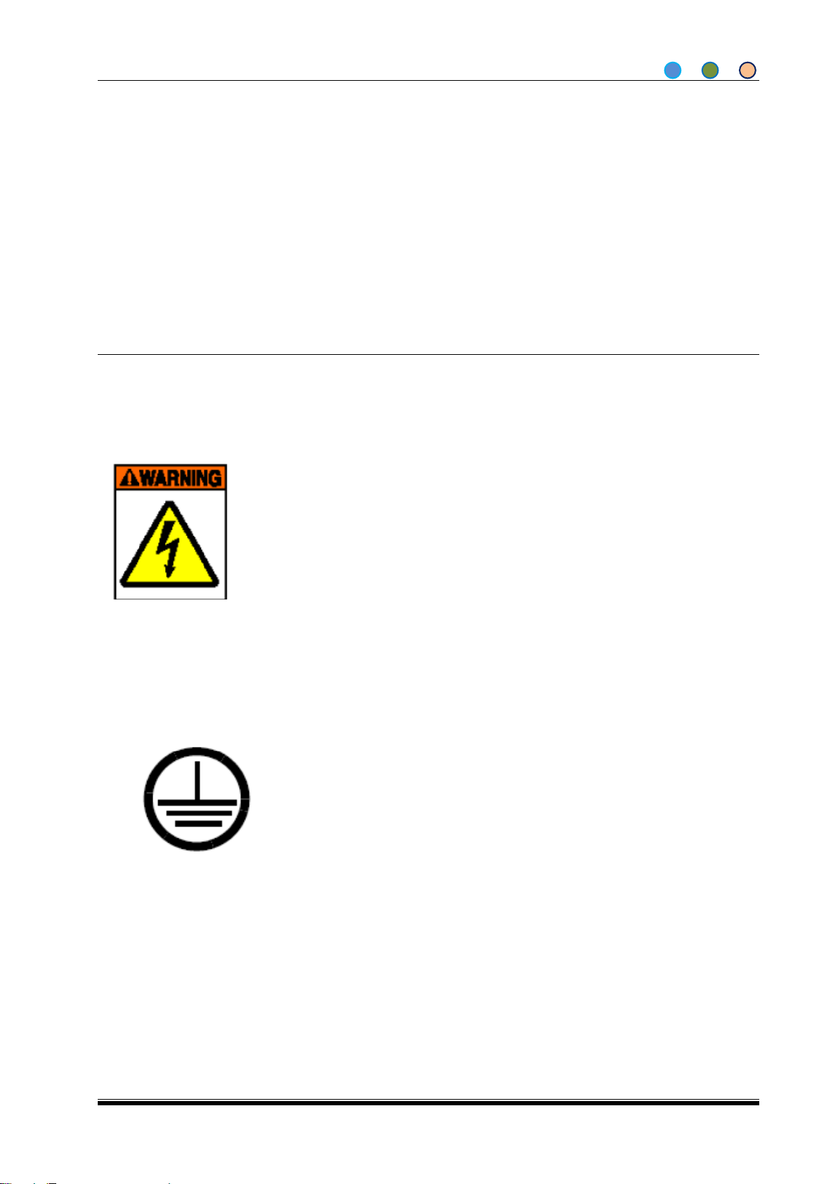
1.3 LABEL
1. High Voltage
This label is located on the back panel of Controller Box.
This label warns the operator that the printer should be well ground connected.
If it’s hiden after installation, please stick another WARNING label in conspicuous place.
Electrical problems should be solved by well-trained engineer.
2. GROUND CONNECTION
This label warns that machine should be ground connected.

OPERATIONAL MANUAL
- 6- D03S THERMAL TRANSFER OVERPRINTER
3. PRODUCT LABEL
SN/ POWER/ RELATED DATA
This label is located on the back panel of Control Box:
Model Number
Factory Location
Serial Number
Electricity Requirements
DK logo
Contact Information

OPERATIONAL MANUAL
D03S THERMAL TRANSFER OVERPRINTER - 7 -
1.4 PARAMETER
Print Head
32mm,300dpi;
Print Area
Intermittent:32mm X 60mm(W X L);
Continuous: 32mm X 150mm(W X L);
TTR Length
Max 500m;
TTR Width
25mm 、33mm;
Print Speed
<40 m/m (Continuous);
Frequency
<200p/m(Intermittent);
Supported Field Types
Time, date, variable data, logo, QR code, Barcode, etc;
Communication
Interface
USB、Ethernet、RS232;
Suitable Voltage
AC110 ~220 V,50/60Hz;
Power
200W;
Work Temperature
0~40℃;
Relative Humidity
10% ~95%(Non Condensing);
Air Supply
0.6 Mpa(maximum),dry,non-pollution
Weight
Printer: 8.5kg,Controller 2.0kg;
Dimension
Printer 190mm×192mm×180mm (L×W×H);
Controller 233mm×180mm×128mm (L×W×H);

OPERATIONAL MANUAL
- 8- D03S THERMAL TRANSFER OVERPRINTER
2. SAFETY
2.1 OPERATION GUIDELINES
Before operating this unit, read this manual thoroughly. Pay particular attention to the WARNINGS AND
CAUTIONS to prevent possible injury to personnel.
1. Please install the main power within 3 meters near the printer.
2. Please make sure air supply must be limited to not greater than 0.6Mpa under any circumstances.
3. Before any maintenance or repair on any part of the printer, disconnect the printer from the power
supply.
4. Please do not put anything between print head and rubber anvil/ rubber roller when the printer is
powered on. Damage to the print head may occur.
5. Please do not run the printer when any covers are taken off.
6. Please do not place the printer in a hazardous environment. Make sure the printer will not turn, move or
topple.
7. The use of incompatible consumables can damage your printer. Use only consumables approved by
DIKAI Company.
8. Please be aware of the danger of power and rub-out signal which can run the printer.
9. Please do move the printer with two hands to make sure not damage the printer.
10. Please do not ignore or remove warning labels on the printer.
11. Please complete detailed inspection of power in, otherwise it will cause the damage of printers.
12. Please install and check the power pocket by qualified electricians to avoid the danger of electro-shock.

OPERATIONAL MANUAL
D03S THERMAL TRANSFER OVERPRINTER - 9 -
2.2 APPLICATION AND ABUSING
The information for the safety, installation, operation, trouble shooting, schematics, parts illustrations and
routine maintenance is listed throughout this manual.
The following operation methods, but not limited to, are considered as abusing:
Maintain the printer without DK authorization.
Do not abide by the safety requirements in this manual.
Connect other brand machine to the printer.
Un-qualified personnel operate or repair the system.
Use unspecified power supply or unsuitable plastic film.
Till this manual is published, the above are the best instructions aiming at providing safe operating,
handling, storing, transporting, discarding and distributing to products, but not guarantee or quality
specification.

OPERATIONAL MANUAL
- 10 - D03S THERMAL TRANSFER OVERPRINTER
3. INSTALLATION
3.1 COMPONENTS
Packing List:
1、D03S Controller
8、Sample TTR
2、D03S Ribbon Cassette
9、Air Tube
3、D03S Printer
10、Drive Cable
4、Air Pressure Regulator
11、Power Cable (no plug)
5、Air Pressure Meter
12、I/O Cable
6、Relay
13、Power Cable
7、USB
Diagraph 2 Components

OPERATIONAL MANUAL
D03S THERMAL TRANSFER OVERPRINTER - 11 -
3.2 INSTALLATION REQUIREMENTS
Please make sure all below index are fully checked before installation.
1. Packaging machine runs well and all the signals are working;
2. Stable power supply: AC 100V-240V±10V (MAX 3A);
3. Compressed air: max. 0.6Mpa, dry and uncontaminated air
4. Reliable printing signal——can be from relay, NPN/ PNP sensor, photo sensor or PLC
5. Enough space for installing printer
6. The installation should be done by DIKAI engineer or well trained operator
3.3 STANDARD BRACKETS
INTERMITTENT
1
2
4
3
1. Square-Shape Side PlateAssembly 2. Fixed Slider Block Assembly
3. Rubber Anvil Assembly 4. Transition Roller Assembly

OPERATIONAL MANUAL
- 12 - D03S THERMAL TRANSFER OVERPRINTER
CONTINUOUS
Note:
Standard bracket lengths are 350mm, 450mm, 500mm, 542mm, 600mm and 770mm.
If standard bracket is not suitable for your packaging machine, do contact DIKAI for technical
supports.
2
3
4
1. Square-Shape Side Plate Assembly 2. Fixed Slider Block Assembly
3. Rubber Roller Assembly 4. Transition Roller Assembly
1

OPERATIONAL MANUAL
D03S THERMAL TRANSFER OVERPRINTER - 13 -
3.4 INSTALLATION OF THE MOUNTING BRACKET
Make sure enough room for the mounting bracket installation and easy operation;
Make sure the bracket is well fixed and the printer roller and the packaging machine roller are parallel;
Mount the Printer Unit after the bracket is well installed, make sure Print head is paralleled to the
rubber roller or rubber anvil;
Make sure the gap between Print head and substrate is within 1.5~2.5mm;
Make sure all the screws used for installation not influence the packing machine running.
In fixing the printer, the key point is to adjust the gap between the printhead (original position) and the
substrate
Note: Use wood, plastics or other non-conductive material instead of metal to measure the gap. Adjust the
gap into proper by adding or removing cushion. The gap is the key to the performance of the machine.
Here’re some disciplines to follow:
1. Make sure the gap is between 1.5-2.5mm;
2. The print head is parallel to the substrate;
3. The substrate is more than 65mm width.
Intermittent:
Peel Roller (Print head) is paralleled to the Rubber Anvil.
A
B
A=B=1.5-2.5mm
c
C≥65mm

OPERATIONAL MANUAL
- 14 - D03S THERMAL TRANSFER OVERPRINTER
Continuous:
Make sure the Print head is pointing to the center of the Rubber Roller. It can be set by parameter “Vertical”
from the Controller.
The gap between Print head and Rubber Roller should be within 1.5~2.5mm, and the wrapping angle is no
more than 120°.
Print head is paralleled to the Rubber Roller.
1.5-2.5mm
<120°

OPERATIONAL MANUAL
D03S THERMAL TRANSFER OVERPRINTER - 15 -
3.5 INSTALLING THE CONTROLLER
The control box is used for setting up the printer, it can access the maintenance and diagnostic function.
1. Mount the controller box away from potential sources of water spray or cleaning solutions.
2. Mount the controller box in the location convenient for operation and taking cables, no more
than 3m from the printer unit.
3. Keep cables be in orderliness.
Take 4pcs rubber cushion off, fix the controller box by M6*16screws, refer to Diagram 3.
CAUTION: Take care when mounting the Controller.Do not use screws which reach more than 10 mm into
the Controller housing and electrical components.
3.6 CONTROLLER CONNECTION POINTS
The connection points for the Controller Box are shown below:
1. USB Connector
Read and download print texts from the pre-loaded USB memory stick.
2. Drive Cable Connector
A D-Type 44-pin connector, connect the drive cable. Please make sure the connection is good to avoid
any damage.
3. Power Connector
Can be connected to packing machine for power supply.
Diagraph 1The bottom of Controller

OPERATIONAL MANUAL
- 16 - D03S THERMAL TRANSFER OVERPRINTER
IMPORTANT: Never connect or disconnect the cables to the D03S control box with the power on. Failure to
do this may result in personal injury or machine damage.
4. Communication Connector
To connect with communication systems to get requested print information.
2. External I/O Connector
I/O connector is a D-type 9-pin connector to get external signal and output “WARNING”, “Error” signal.
3. SD Card Connector
Update interface.
4. Ethernet Connector
Connect with Ethernet.
I/O Connector Instruction:
PIN
Description
Color
1
NC
Brown
2
SIG+ print signal +
Black
3
SIG- print signal-
Blue
4
ERR1+ Alarm Output 1 COM 1
Purple
5
ERR2+ Alarm Output 2 COM 1
Green
6
NC
Red
7
ERR1+ Alarm Output 1 NO 2
Orange
8
ERR2+ Alarm Output 2 NO 2
Yellow
9
NC
Grey

OPERATIONAL MANUAL
D03S THERMAL TRANSFER OVERPRINTER - 17 -
3.7 PRINTER CONNECTORS
Connectors on Printer
1. Encoder Connector
For continuous printers, an encoder is required to monitor the speed of the packaging film.
D03S requires the encoder to provide:
Operating at 24V DC.
500 pulses per rev.
1-USB
Diagraph 2Connectors on Controller
5-I/O
2-Drive Cable
3-Switch
4-Communication
6-SD Card
7—Ethernet
Diagraph 5 Connectors on Printer
2-Air Inlet
1-Encoder
3-Drive Cable

OPERATIONAL MANUAL
- 18 - D03S THERMAL TRANSFER OVERPRINTER
Out dia. 53.05mm tracking wheel
Standard DK Encoder is a DB9 connector, can be insert to printer.
2. Air Inlet:
D03 requires the compressed air 0.25Mpa~0.45Mpa
Set the air pressure by the followings:
1. Mount the air pressure regulator: the IN connects 6mm air tube and the OUT connects 4mm air
tube to join with the Air Inlet of printer.
2. The value on regulator should be between 0.25-0.45Mpa;
3. If not, pull out the knob, rotate clockwise to increase the pressure, or count-clockwise to decrease
the pressure into proper (green area).
Diagraph 3Encoder

OPERATIONAL MANUAL
D03S THERMAL TRANSFER OVERPRINTER - 19 -
4. Press the Knob to lock the pressure regulator.
3. Drive Cable Connector
A D-Type 44-pin connector, connect with the drive cable.
At no point should the unit be powered until these are securely attached to each unit.
Diagraph 4Air Pressure Regulator
Φ6mm air inlet
Φ4mm air outlet
Filter

OPERATIONAL MANUAL
- 20 - D03S THERMAL TRANSFER OVERPRINTER
3.8 PRINT SIGNAL
Print signals are provided by packing machine or extra sensor. When connect with packing machine, an extra
relay is needed to avoid short circuit between packing machine & D03S.D03S prints once when the relay
finish a closing course. If print signal is provided by extra sensor, D03S prints once when it changes from low
to high voltage.
Please refer to 3.9 I/O Cable Connection for detailed wire connection.
Note: Defaulted print signal is PLC, for other print signal, switches should be changed according to below
instruction.
3.9 I/O CABLE CONNECTION
1. Connect Print Signal
Currently only accept PLC signal, below is detailed wire connection:
Remark:
PRISIG+:Print Signal +, Pin 2 in I/O cable, color black;
PRISIG-:Print Signal -, Pin 3 in I/O cable, color blue;
PRISIG+, PRISIG- are passive, after connected, max current consumption is 20 mA.
1) NPN type PLC wire connection:
2) PNP type PLC wire connection:
PRISIG+ black
PRISIG- blue
Controller
Print Signal
PLC: +24V
NPN type PLC
Table of contents
Popular Industrial Equipment manuals by other brands

PAW
PAW K36E Installation and operation instruction

Endress+Hauser
Endress+Hauser OUSTF10 operating instructions

Grundfos
Grundfos Selcoperm SES Series Installation and operating instructions

SEW-Eurodrive
SEW-Eurodrive SPIROPLAN W Gear Unit Series Assembly and operating instructions

GE
GE VT-700 instruction manual

SCHUNK
SCHUNK CLM Assembly and operating manual

AUGIER Energy
AUGIER Energy DIAM 3100 Installation & maintenance

ABB
ABB Terra 94 installation manual

KROHNE
KROHNE ALTOSONIC V12 Operation and installation manual

Geovent
Geovent ASA-3 Series instruction manual

Toshiba
Toshiba GRB200 instruction manual

HyQuest Solutions
HyQuest Solutions TB1L instruction manual