Dikkan DN15 User manual

Doc. No: FRM.65 Rev. No: 00 Rev. Date: 01.06.2015
OPERATING INSTRUCTIONS
GLOBE VALVES APPLICATION
&
MAINTENANCE
JUNE, 2015
WARNING
This manual is exclusive property DIKKAN, under copyright and any not authorized reproduction, in
part or in total, shall be prosecuted.
Read and follow instructions carefully. Proper training and periodic review regarding the use of this
equipment is essential to prevent possible serious injury and/or property damage.
Shown products are according the current production. Dikkan reserves to modify product
characteristics according technical evolution or customer special request. Verify if manual comply
with used product.

Doc. No: FRM.65 Rev. No: 00 Rev. Date: 01.06.2015
CONTENTS
1.
SAFETY TERMS………………………………………………….……………………………………………..…….
1
2.
TECHNICAL FEATURES…………………………………………….……………………………………...............
1
3.
DESCRIPTION……………………………………………………………………………………….………………..
2
4.
HOW TO MEASURE VALVES….………………………………………………………………………….………..
3
5.
GLOBE VALVE PART LIST…………..…..………………………………………………………………..………..
4
6.
PROTECTION DURING STORAGE AND TRANSPORT………………………………………………………...
5
7.
INSTALLATION………………………………………………………………………………………….…………….
5
7.1 Installation Position…………………………………………………………………………………………......
7
8.
MAINTENANCE………………………………………………………………………………..………………………
8
8.1 Replace the Gland Packing…………………….………………………………………………………...…….
8
8.2 Replace the Gasket…………………………………….……………………………...………………………...
9
8.3 Metal to Metal Sealing……………………………….……………………………………………………...…..
10
9.
OPERATION…………………………………….……………………………………….…………………………….
11
9.1 Bypass Disc…………………….……………………...…………………………………………………...…….
11
10.
RECYCLING…………………………………….……………………………………..……………………………....
12
11.
PRESSURE EQUIPMENT DIRECTIVE (97/23EC) AND CE MARKING……………………….…………….…
12
12.
SAFETY REMARKS……………………….……………………………………………………….………………...
12
13.
TROUBLESHOOTING.....………………………………………………………………….…………………………
13
14.
WARRANTY…..…………………………………………………………………….………………………………….
13
15.
NOTES……………………………………………………………………………………..…………………………...
14

Doc. No: FRM.65 Rev. No: 00 Rev. Date: 01.06.2015
1
1. SAFETY TERMS
The signal terms DANGER, CAUTION and NOTICE are used in this operating manual in the event of notices related
special dangers, or for unusual information, requiring a special marking.
Danger infers that there is the danger of life and considerable damage in the event of non-compliance.
Caution infers that there is the danger of injuries and damage in the event of non-compliance.
Notice infers that attention is drawn to technical correlations/connections.
2. TECHNICAL FEATURES
Standard: DIN 86251, DIN86252, DIN 86260, DIN 86261, EN 13709, DIN 3356
Face to Face: Straight Form - EN 558 Series 1 (DIN 3202 F1) / Angle Form - EN 558 Series 8 (DIN 3202
F32)
Flange Dimension: EN 1092-1, EN 1092-2, EN 1092-3
Material: Cast Iron, Ductile Iron, Cast Steel, Stainless Steel, Bronze
Type: Stop Type, SDNR Type, Regulating Disc, Bypass Disc
Application: Steam, fresh water, air, oil, seawater, feed water, cold and hot water, gases
Operation: Manual by handwheel (Option: Electric, Pneumatic, Hydraulic Actuator)
Pressure & Temperature Ranges
Cast Iron, Ductile Iron,
Bronze
Working Pressure
[bar]
Cast Steel,
Stainless Steel
Working Pressure
[bar]
Bore
120 ℃
180 ℃
Bore
120 ℃
DN15-DN200
16
10
DN15-DN150
40
DN250
10
6
DN175-200
16
DN300-DN350
6
4
DN250-DN300
10
DN400-DN600
4
2
DN350
6
DN400-DN600
4
Valves must not be used at higher “pressure & temperature” than defined “working pressure &
temperature”.

Doc. No: FRM.65 Rev. No: 00 Rev. Date: 01.06.2015
2
3. DESCRIPTION
Globe valves are named for their spherical body shape.
A Globe valves is a linear motion valve and are designed to close off, open up or regulate the flow in a pipeline. The
disc is designed to stop flow and a tight seal with pressure under the disc. In the 10% open position to full open position,
globe valves are efficient in throttling line pressure. Continuous throttling at less than 10% open may cause noise &
vibration, wear and damage to discs and seats. SDNR valves are used as non-return valves protecting the plant against
back flow of medium and additionally they can shut off the flow. Regulating disc is a spherical shape that makes it a
better choice for regulating applications. Bypass disc is for higher differential pressures. In such cases pressure must
be over the disc.
Globe valves are operated by handwheel manually. If required, valves can be produced suitable for gearbox,electrical,
pneumatic or hydraulic actuator installation. General features of the globe valves are as follows;
•Bolted bonnet,
•Outside screw and yoke
•Rotating rising stem & handwheel
•Metallic or soft seating surfaces
•Special trims available
•Flanged
•Backseat

Doc. No: FRM.65 Rev. No: 00 Rev. Date: 01.06.2015
3
4. HOW TO MEASURE VALVES
It is very important to supply dimensions as described below as well as pressure, temperature and medium information,
to request or purchase the exact valve as per your needs.
ØD: Outside Flange Diameter
Øk: Hole Circle Diameter
ØdxQty.: Diameter of Bolt Holes x Number of Bolt
Holes
L: Face to Face Length
L1 / L2: Face to Center Length
(Raised face is included in
length)

Doc. No: FRM.65 Rev. No: 00 Rev. Date: 01.06.2015
4
5. GLOBE VALVE PART LIST
.

Doc. No: FRM.65 Rev. No: 00 Rev. Date: 01.06.2015
5
6. PROTECTION DURING STORAGE AND TRANSPORT
•Valves should be stored in a closed place where will not be exposed to direct to sunlight.
•Valves shall be kept on pallets, avoiding any direct contact with the ground.
•Valves shall be protected from any external effects and mechanical damages in the storage place.
•Valves shall be protected from dust and dirt.
•Valves, keep the packaging until the moment of installation. (In valve packaging to prevent sweating, you are
not allowed to sudden changes in temperature in the storage area)
•Keep the valve in the storage space heat and flame sources.
•Protect the valve from excessive vibration during transportation.
•Optimum storage temperature is 5°C to 40°C.
•During the storage, it should be assured that the discs of the valves are in closed position. (except for
soft seal valves)
•Unload all valves from wooden pallets carefully to the ground without dropping. When lifting, the valve should
be secured by the body and never lifted by the trim.
•Good condition of stored products must be periodically verified.
7. INSTALLATION
•Pipelines and pipeline systems have to be installed in such way that no tensions from thermal expansion (or
other) of the pipeline may have impact on the valves. This can theoretically even lead to breaks in the valves,
causing danger from medium spills. DIKKAN offers suitable expansion joints for this purpose.
•Before installation, the pipeline must be cleaned off all dirt such as sand, dust, welding residues etc. Use
strainers, in suitable sections of the pipeline, for future protection of the valve from dirt and foreign substances.
•Verify that the valve is suitable for the operating specifications of the medium (installation); such as maximum
operating pressure, maximum operating temperature, corrosiveness and abrasiveness, etc.
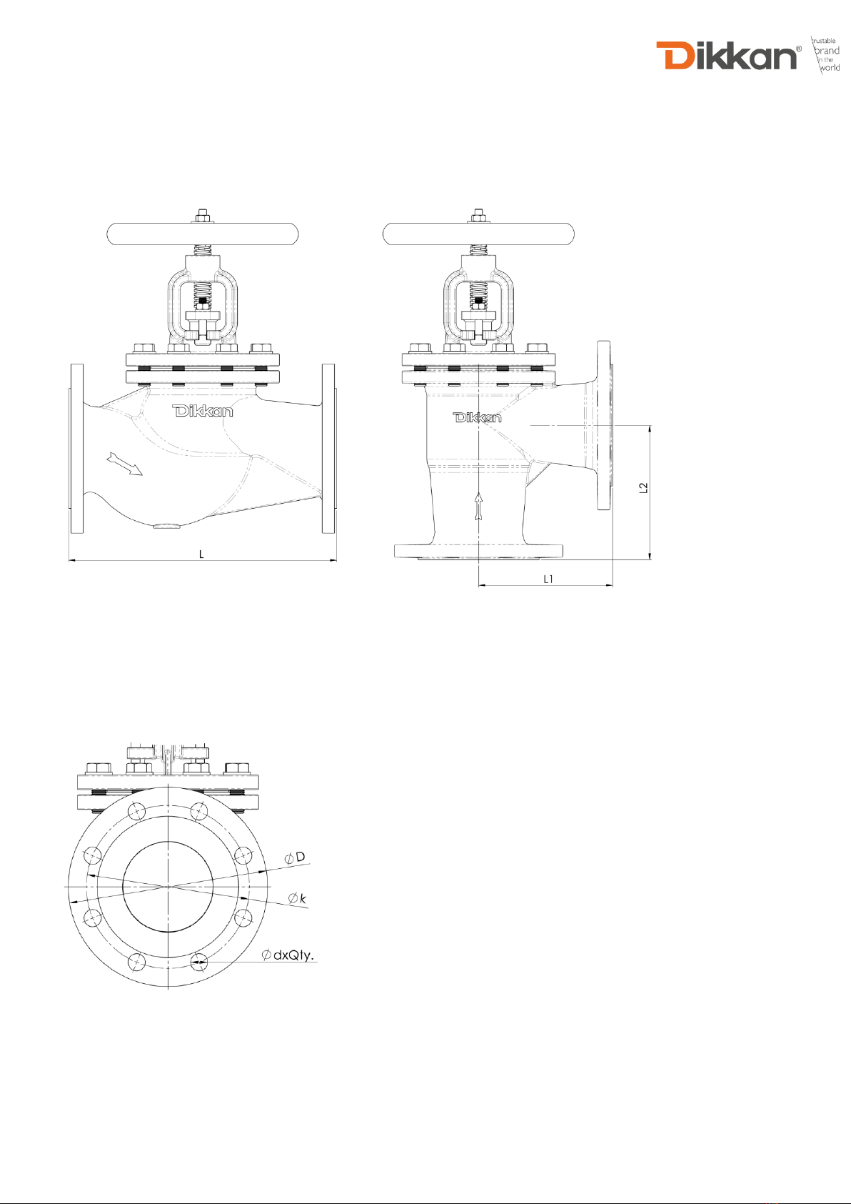
•Verify that the distance between the flanges, where the valve will be connected, is equal to the length of the
valve body.
•All protection devices for transport and storage have to be removed before installation.
•The arrow on the valve body must be in the same direction of the liquid flow. Valves without on the arrow mark
can be installed with bidirectional piping.
•Valves shall be assembled to the pipeline in fully closed position.
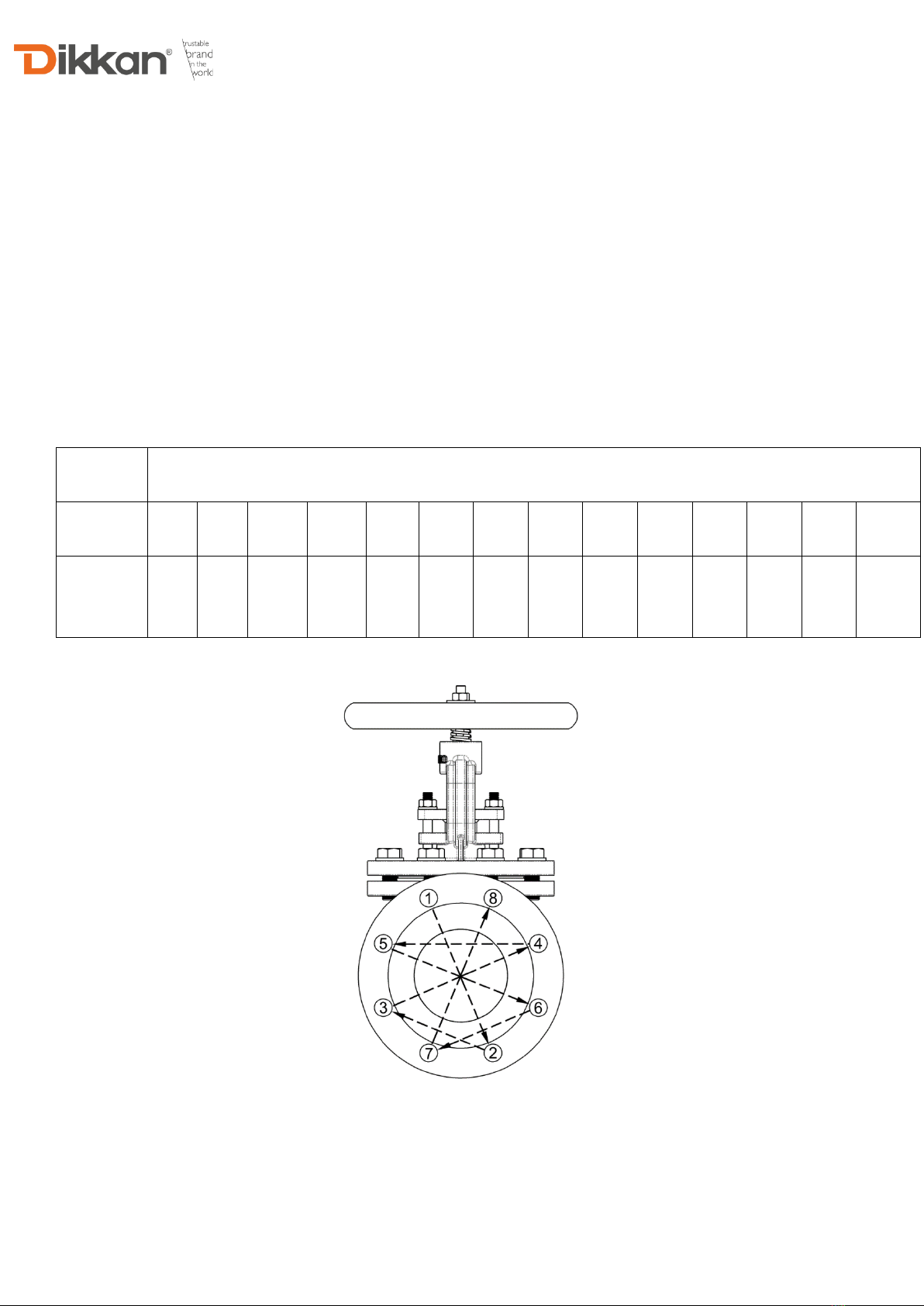
•Use gaskets between the valve flanges and the counter flanges. The gasket should be suitable for operation
conditions or maximum pressure/temperature ratings.
•The flanges which the valve will be assembled should be in the same axis and the flange surfaces should be
parallel to each other.

Doc. No: FRM.65 Rev. No: 00 Rev. Date: 01.06.2015
6
•The bolting must be checked for correct size, length, material and that all connection flange bolt holes are
utilized. Tighten the bolts and nuts in the crossover method shown in Fig. 1, to load the pipe and valve evenly
and prevent stress on the joints. Finally tighten bolts to correct torque levels as recommended in Table. Do not
overtighten.
•To avoid effects of weight and stress of the piping system to the valves, all piping systems should contain
independent support mechanisms.
•After the installation process is completed, check the connections for leaks with water. Do not use the valve if it
is leaking.
•During installation prevent to damage the paint of the valve.
Hex Head Bolt - Grade 8.8
Metric
M10
M12
M16
M20
M24
M27
M30
M33
M36
M39
M45
M52
M56
M64
Torque
(Nm)
50
87,2
210,8
411,9
711
1048
1422
1932
2481
3226
4992
7747
9650
14416
Fig.1

Doc. No: FRM.65 Rev. No: 00 Rev. Date: 01.06.2015
7
7.1 Installation Position
SDNR Type;
SDNR type valves without spring can only be installed in horizontal pipes in a vertical position
Stop Type;
Stop type globe valves can be installed in any position. However, the best installation position is with the stem pointing
vertically upwards.

Doc. No: FRM.65 Rev. No: 00 Rev. Date: 01.06.2015
8
8. MAINTENANCE
Dikkan globe valves are designed to have minimum maintenance. But if you carry out the following maintenance, they
will increase the longevity and reliability of the valve.
Valves shall be dismounted from pipe line before maintenance and shall be cleaned from medium.
Maintenance work must be performed by qualified, trained and skilled people according to
maintenance instructions Welding is not accepted on valves repairing.
•In very seldom used places, valves should be performed open-close every 3-4 months.
•The stem threads that are exposed to atmosphere should be periodically lubricated, with quality grease.
•Bonnet bolt tension should be checked periodically when valves are used in high temperature applications
where loosening may occur. Although leaks through ring joints are rare, erosion or corrosion could cause rings
to fail. In these cases, a new ring gasket is required.
•The valve gland packing should be inspected at least monthly. If the gland packing shows signs of leakage,
simply tighten the adjusting nuts (P.No15) to compress the packing. Do not over-tighten the adjusting nuts as
this will make operation of the valve more difficult. If, after tightening the adjusting nuts to their fullest extent, the
leakage does not stop, it is then necessary to replace the gland packing.
8.1 Replace the Gland Packing
At any circumstances, packing replacement is dangerous and not recommended for the valves
under pressure. Even the valve is back seated; it is not possible to make sure that any particle is avoiding
backseat to be at full closed position.
Backseat function shall only be used for avoiding or minimizing leakage of medium left in the line after
shutting down the line and taking away the line pressure. Rather than attempting to repack under pressure, it
is preferable to use the backseat to control the stem leakage until a shutdown provides safe repacking
conditions.
Valves shall not be retained fully back seated during usage. This may yield packing to dry and cause
the valve leakage. After the valve has been opened fully, rotate the hand wheel quarter turn towards the close
position.
Unscrew nuts (P.No15) and raise gland (P.No12). Remove all of the old gland packing with packing hook. Clean the
stuffing box and stem.

Doc. No: FRM.65 Rev. No: 00 Rev. Date: 01.06.2015
9
Cut packing by using a spare stem, a mandrel with the same diameter as the stem (Fig.2). Hold the packing tightly on
the mandrel, but do not stretch excessively. Always cut the packing into individual rings. Rings should be cut with a butt
joint (Fig.3). Cut the ring (Fig.4). Install one ring at a time. Seat each ring firmly; making sure it is fully seated before the
next ring is installed.
Do not use a pointed tool to push the rings into position. When inserting the packing rings, the butt joints offset 180°
from each other (Fig.5). When enough rings have been individually seated so that the nose of the gland will reach them,
individual tamping of the rings should be supplemented by the gland. Bring down the gland and tighten nuts balanced
(P.No15), sufficiently while allowing the stem to operate smoothly.
8.2 Replace the Gasket
Depressurize the system and remove the valve from pipe line before bonnet disassembly.
Disassembly the valve will become out of warranty. Please consult Dikkan before disassembling if the
valve is under warranty.
▪Bonnet Disassembly
a) Operate the valve until it becomes full open position.
b) Remove bonnet bolts (P.No17) by using crossover method.
c) Lift up the bonnet assembly, taking care not to damage the disc.
▪Gasket Replacement
a) Discard the old gasket. (P.No4)
b) Inspect the gasket seating surface of the body for wear, damage or deterioration.
c) Polish gasket seating surface with sandpaper to clean rust, dirt and remnant of gasket.
d) Clean the surface to remove all polishing residue.
e) Install a new gasket.
Fig.2 Fig.3 Fig.4 Fig.5

Doc. No: FRM.65 Rev. No: 00 Rev. Date: 01.06.2015
10
▪Body-Bonnet Assembly
a) Inspect the bonnet bolts to ensure that it is not damaged. Any damaged bolts should be replaced.
b) Place the entire bonnet assembly onto the valve body, taking care not to damage the disc.
c) Tighten the bolts in the crossover method like a shown in Fig. 1.
d) Test the valve as required, and place the valve back into service.
8.3 Metal to Metal Sealing
If the seat examination shows only small defects, it is possible to renew seat sealing surface lapping the seat with the
special tool and immediate action is necessary.
To repair the disc seat or body seat, the valve must be removed from pipe line, then use the following procedure:
a) Using a thick polishing paste, alternately turn clockwise and counterclockwise about 90°, softly pressing. Lift up often
and turn the tool, changing its contact position with seat. Go on with lapping until any defect disappears, adding, polishing
paste if necessary. And then clean the seat and repeat treatment using a thinner polishing paste.
b) Remove lapping tool and clean carefully the seat, using a washing agent.
c) After lapping, it is recommended that the surface of the seat and disc be checked for proper contact using marking
blue. Coat the body seats with marking blue, and tightly press the disc into the body seats by hand. Remove the disc,
and examine to make sure there is continuous contact between the sealing surfaces of the disc and body seat.
d) If such contact is not homogen, repeat steps a, b and c until excellent contact is obtained. If disk defect is greater, a
trial to repair it can be performed metal cutting the sealing surface of disk on a lathe. After metal cutting perform lapping
as indicated above.

Doc. No: FRM.65 Rev. No: 00 Rev. Date: 01.06.2015
11
9. OPERATION
•Globe valves are operated manually by handwheel. The handwheels are designed such that reasonable effort
exerted by the operators is sufficient to operate the valve. All Dikkan globe valves have open and closed marked
on the hand wheels along with directional arrow. To open, turn the handle in a counterclockwise direction. To
close, turn the handle in a clockwise direction. Whenever possible, open and close the valve slowly. This is
particularly important in piping systems containing liquids where quick valve closure (with other factors) could
lead to the possibility of an undesirable pressure surge (water hammer) in the piping system.
•Level indicator models, you can follow the valve open- close rates on the level indicator.
•If the hand wheel is difficult to turn, loosen packing nut ¼ to ½ turn. Retighten packing nut after open-close
operation is completed.
9.1 Bypass Disc
Valves with balancing plugs have to be installed with medium flowing over the plug (a) as indicated by flow direction
arrow on valve body. When the valve is closed, anticlockwise rotation of the hand wheel lifts the pilot plug (b) off the
larger balancing plug (a). This allows the medium to pass through the plug and equalizes the pressure of the medium
under the plug (a). After the pressures have been equalized within the values stated, the valve can be opened by turning
the valve further with normal manual force.

Doc. No: FRM.65 Rev. No: 00 Rev. Date: 01.06.2015
12
10. RECYCLING
Product can be recycled. If suitable procedure has been respected, no environment pollution risk occurs. When the
recycling of the product is made, the country's laws, rules and regulations must be observed.
11. PRESSURE EQUIPMENT DIRECTIVE (2014/68/EU) AND CE MARKING
Dikkan globe valves comply with the requirements of the European Pressure Equipment Directive 2014/68/EU. Valves
are categorized in accordance with the maximum working pressure, size and ascending level of hazard, which is
dependent on the fluid being transported. Fluids are classified as Group 1, dangerous fluids or Group 2, all other fluids
including steam. Categories are SEP (sound engineering practice) and for ascending levels of hazard, I, II, III or IV. All
valves designated as SEP do not bear the CE mark nor require a Declaration of Conformity. Dikkan valves with a CE
marking have a declaration of conformity which includes information about the applied conformity assessment
procedure. It has been confirmed that the quality assurance in design control, manufacture and the manufacturer’s final
acceptance of Dikkan Globe Valve by notified body.
12. SAFETY REMARKS
•The operating instruction has to be observed in an obligatory way. In the event of mismatch, all warrants and
liabilities are reserved.
•Sharp edges and burrs can cause injuries.
•The valves must be mounted, started up or serviced by fully trained and qualified personnel only
•Maintenance staff must be elucidated about the dangers pertaining to disassembling and mounting of valves
as well as electric and machinery installations
•Safety goggles and other appropriate protective gear should be used. Failure to do so could result in serious
injury.
•At all work at a valve installed in a pipeline it has to be made sure that the plant is not under pressure and not
medium can leak from the pipeline.
•Be sure that any dangerous or combustible or detonating gas or fluid has been depressurized from product and
connected piping, to avoid any danger to maintenance people due to contact or inhalation.
•Preserve valve specific maintenance manual in conjunction with this manual and let them reachable by
maintenance staff. Be sure that maintenance staff read any part of those manuals before any use or
maintenance operation.

Doc. No: FRM.65 Rev. No: 00 Rev. Date: 01.06.2015
13
13. TROUBLESHOOTING
Be sure to observe the safety instructions during troubleshooting.
Fault
Possible Cause
Corrective Action
Valve leaking around
stem and gland
T-Bolts loose
Tighten T-Bolts
Damaged or worn gland packing
Refer to the "8.1 Replace the Gland
Packing" sections of this manual
Damaged stem
Replace stem
Valve leaking around
bonnet
Body-Bonnet bolts loose
Tighten body-bonnet bolts
Damaged bonnet gasket
Refer to the "8.2 Replace the Gasket"
sections of this manual
Valve leaking around pipe
connections
Flange bolts loose
Tighten flange bolts
Damaged flange gasket
Replace flange gasket
Valve hard operate
T-Bolts too tight or tightened unevenly
Loosen T-Bolts, re-tighten T-Bolts evenly
If the valve has not been operated over for a
long time, may stem is stuck
Lubricate stem threads with grease
Valve does not pass flow
Check flow arrow direction on valve body
The arrow on the valve body must be in the
same direction of the liquid flow
Flange covers not removed
Remove flange covers
The valves and pipeline must be protected
against freezing media
Warm up pipeline system and use valve
jacket
Valve seat leaking
Dirt or debris between sealing surfaces
Open valve to flush or clean sealing
surfaces
Damaged disc seat or body seat
Refer to the "8.3 Metal to Metal Sealing"
sections of this manual
Low flow rate
Blockage in the pipeline system
Check pipeline system
Breaking the valve parts
Damage to the parts bearing pressure
because of water hammer
To avoid water hammer, where necessary
in the pipeline system, place water hammer
protective equipment
14. WARRANTY
Warranty Period: 18 Months
The warranty shall not cover maintenance work, installation of external parts. When unoriginal parts are used for
replacement, warrants and liabilities become invalid.

Doc. No: FRM.65 Rev. No: 00 Rev. Date: 01.06.2015
14
15. NOTES
This manual suits for next models
8
Table of contents
Popular Control Unit manuals by other brands

American Backflow
American Backflow Deringer 20 manual

Leonard
Leonard TMS-25 INSTALLATION ADJUSTMENT SERVICE

Freescale Semiconductor
Freescale Semiconductor TWR-KL25Z user manual

TQ-Systems
TQ-Systems TQMLS1028A user manual

Emerson
Emerson Fisher 1808 manual

US Water Systems
US Water Systems Defender 223-DFROM Series owner's manual