diLUSSO TH602MSL Guide

1
TELESCOPIC HOOD
TH602MSL
TH604MSL
INSTALLATION MANUAL
USER MANUAL
Read this manual carefully before
operation to avoid risk of accident or
damage to the appliance
Images in this manual are for reference only, refer to physical unit for exact
dimensions
.

2
TABLE OF CONTENTS
SECTION
PAGE
Important Notes
3
Components
4
Dimensions
5
Installation
6
How to Use
9
Maintenance
10
Troubleshooting
12
3
Congratulations on the purchase our cooker hood. Before installing and/or using the cooker hood
carefully read all the instruction.
IMPORTANT NOTES
The instructions for use apply to several versions of this appliance. Accordingly, you
may find descriptions of individual features that do not apply to your specific appliance.
INSTALLATION
The manufacturer will not be held liable for any damages resulting from incorrect or
improper installation.
The minimum safety distance between the cooker top and the extractor hood is 650
mm (some models can be installed at a lower height, please refer to the paragraphs
on working dimensions and installation).
Check that the mains voltage corresponds to that indicated on the rating plate fixed to
the inside of the hood.
For Class I appliances, check that the domestic power supply guarantees adequate
earthing.
Connect the extractor to the exhaust flue through a pipe of minimum diameter 125mm.
The route of the flue must be as short as possible.
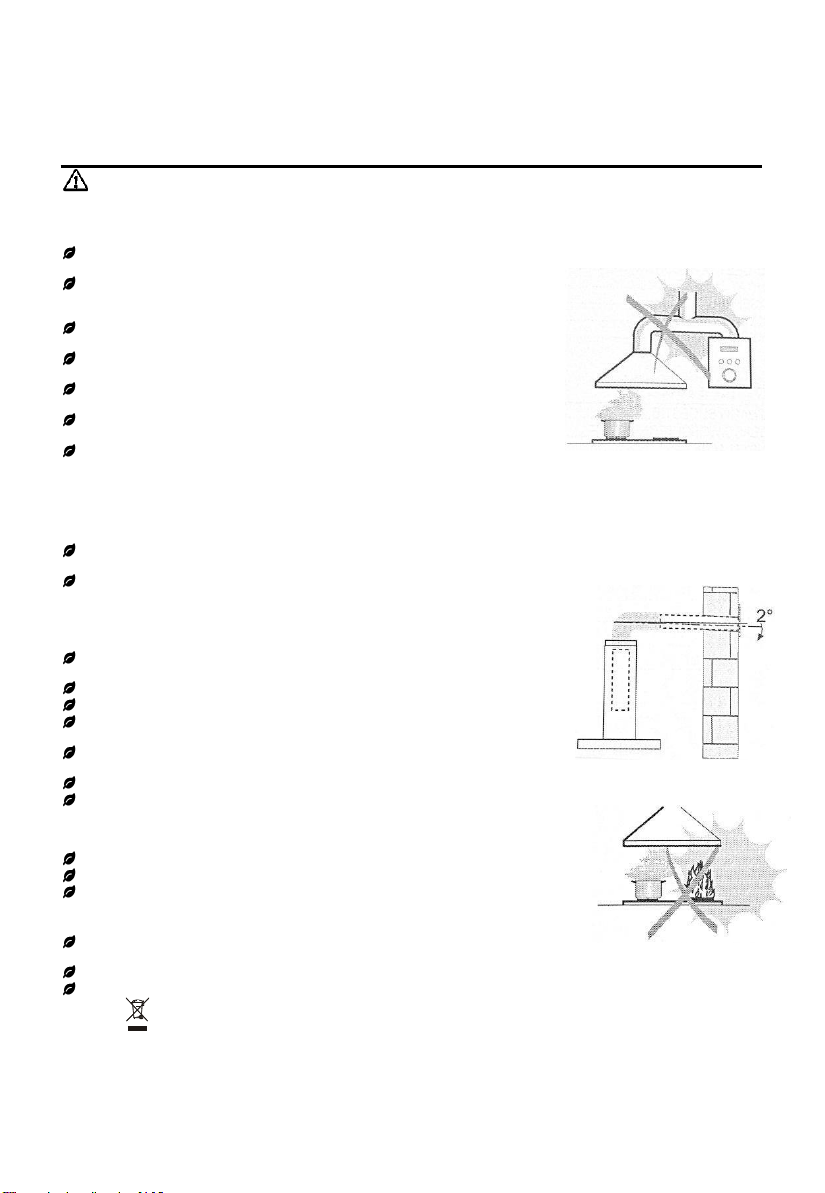
Do not connect the extractor hood to exhaust ducts carrying combustion flumes
(boilers, fireplaces, etc.).
If the extractor is used in conjunction with non-electrical appliances (e.g. gas burning
appliances),a sufficient degree of air circulation must be guaranteed in the room in
order to prevent the backflow of exhaust gas. The kitchen must have good ventilation
to guarantee the entry of clean air. When the extractor hood is used in conjunction with
appliances supplied with energy other than electric, the negative pressure in the room
must not exceed 0,04 mbar to prevent fumes being drawn back into the room by the
extractor hood.
In the event of damage to the power cable, it must be replaced by the manufacturer or
by the technical service department, in order to prevent any risks.
If the instructions for installation for the gas hob specify a greater distance specified
above, this has to be taken into account. Regulations concerning the discharge of air
have to be fulfilled.
USE
The extractor hood has been designed exclusively for domestic use to eliminate
kitchen smells.
Never use the hood for purposes other than for which it has been designed.
Never leave high naked flames under the hood when it is in operation.
Adjust the flame intensity to direct it onto the bottom of the pan only, making sure that
it does not engulf the sides.
Deep fat fryers must be continuously monitored during use: overheated oil can burst
into flames.
Do not have a naked flame under the extractor hood due to risk of fire.
This appliance is not intended for use by persons (including children) with reduce
physical, sensory or mental capabilities, or lack of experience and knowledge, unless
they are being supervised or given instructions concerning the use of theappliance
by a person responsible for their safety.
Children should be supervised to ensure that they do not play with the appliance.
Cleaning and user maintenance shall not be made by children without supervision.
“CAUTION: Accessible parts may become hot when used with cooking appliances”.
MAINTENANCE
Switch off or unplug the appliance from the mains supply before carrying out any
maintenance work.
Clean and/or replace the Filters after the specified time period (Fire hazard).
Clean the hood using a damp cloth and a neutral liquid detergent.
The symbol on the packaging indicates that this product may not be treated as
household waste. By ensuring this product is disposed of correctly, you will help prevent
potential negative consequences on the environment and human health, which could
otherwise be caused by inappropriate waste handling of this product. For more detailed
information about recycling of this product, please contact your local city office, your
household waste disposal service or the shop where you purchased the product.
4
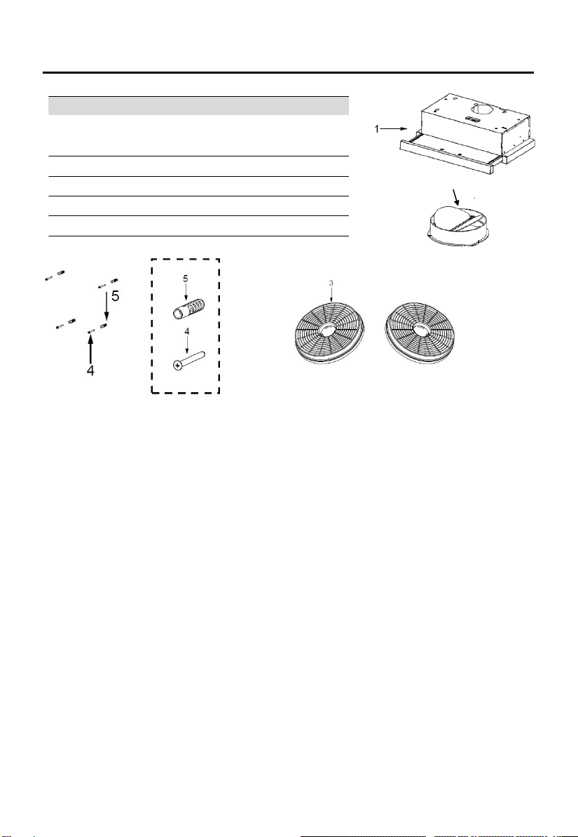
Ref.
Qty.
Product
Components
1
1
Hood Body, complete with: Controls, Light,
Motor,
Filter.
2
1
Butterfly valve
3
2
The Activated Charcoal
filter
(1 / 2
optional
)
4
4
Screws5
x
50
5
4
Wall
Plugs
2
COMPONENTS

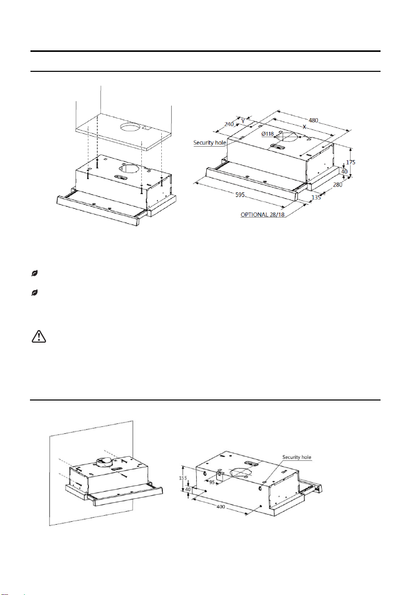
5
Model
X
Y
TH602MSL
400
75
TH604MSL
423
88
OPTIONAL 43/80
136
280
175
DIMENSIONS
unit:mm
595
527
Min.
Min.
650
6
INSTALLATION
METHOD 1
Referring to the above diagram, align the position of the hood with the cabinet. Insertthe 4
screws (supplied) intothescrew holes and tighten.
Screws should be fastened firmly, ensure that the hood is securely fastened to the cabinet
and is stable before using.
Warning
When cutting or drilling into wall or ceiling, do not damage electrical wiring or
other hidden utilities.
METHOD 2
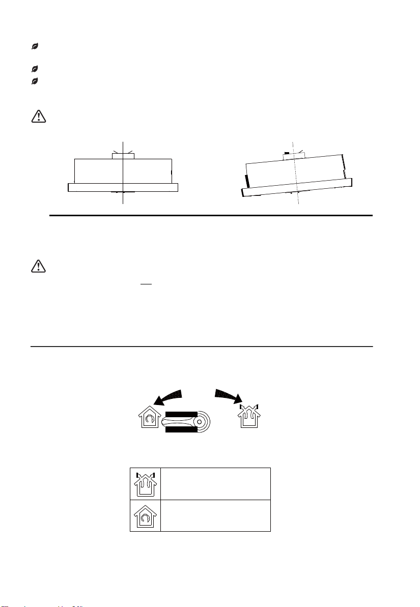
7
To mount on the wall, insert and secure 2 screws (supplied) into the relative position of the 2
screw holes on the back of hood.
Also install screws in the security hole positions, to further stabilise the hood.
Ensure hood is secure and stable before using.
Warning
Right
Wrong
Warning
The extractor hood must not be installed and connected to flues where other appliances are
installed and share power connection with other appliances
VENTING MODES
If your hood has dual mode extraction, locate the venting knob on the front of the motor casing.
Select extraction mode.
Venting mode selector
Ducted mode:
Exhaust is extracted outside
the house.
Recirculating mode:
Exhaust is filtered and
recirculated inside.

8
DUCTED MODE
Insert the butterfly valve into the flue hole, and turn clockwise to secure. The butterfly valve must
be used for ducted mode.
When installing the ducted version, connect the hood to the outlet
vent using either a flexible or rigid pipe ɸ150 or ɸ120 mm, the
choice of which is left to the installer.
To install a ɸ120 mm air exhaust connection, insert the reducer
flange on the hood body outlet over the butterfly valve.
Fix the ducting using sufficient pipe clamps (not
supplied). Use minimal bends in the ducting for optimal power, increasing bends may reduce
performance of your hood
Ducting can extend either through the wall or the roof. Do not terminate the vent system in an
attic or other enclosed areas.
Remove possible charcoal filters.
RECIRCULATING MODE
The butterfly valve does not need to be installed when using recirculating mode.
Ensure the venting knob points to recirculating mode and the vents in front of the hood are not
blocked when hood is use. Ensure both charcoal filters and aluminum filters are installed. Charcoal
filters need to be replaced at regular intervals, refer to Maintenance section.
9
HOW TO USE
Before using
Check the condition of the appliance:
Check whether there are visible defects.
Check that all parts of the appliance have been securely fitted.
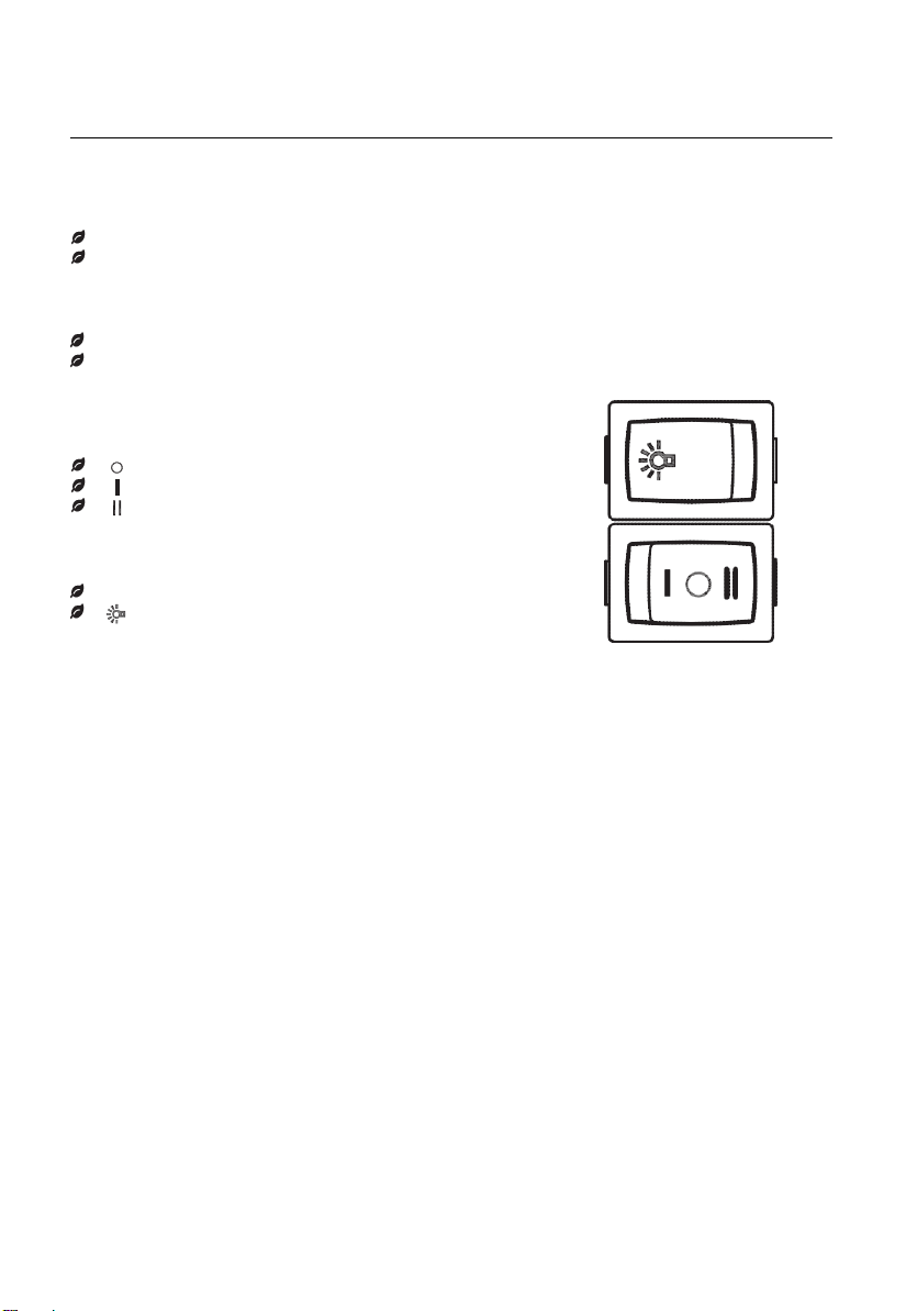
Switching on/off
Pull out the fascia and locate the switches on the right.
There are 2 speeds for the motor and on/off switch of the light.
Motor Operation
[ ]=Off
[ ]=Low Power Setting
[ ]=High Power Setting
Light Operation
[ ]=Off
[ ]=On

10
MAINTENANCE
GREASE FILTERS
CLEANING ALUMINIUM FILTERS
The filters must be cleaned every month of operation, or more
frequently for particularly heavy usage, and can be washed in a
dishwasher.
Press the anchoring hinge to release them.
Remove the filters one by one pushing them towards the back
side of the hood unit and simultaneouslypulling downwards.
Do not bend the filters. Before fitting them again into the hood make
sure that they are completely dry. (The color of the filter surface may
change over time but this has no effect on the filter’s efficiency).
When re-fitting the filters into the hood ensure they are mounted in
the correct position and the anchoring hinge is at the front.
ACTIVATED CHARCOAL FILTERS (RECIRCULATING MODE)
These filters are not washable and cannot be regenerated, and must be replaced approximately
every 4 months of operation, or more frequently with heavy usage. Contact the retailer or
manufacturer to purchase replacements.
Remove the aluminum filters
Remove the saturated activated charcoal filters.
Fit the new charcoal filters.
Reinstall the aluminum filters.
IMPORTANT
When activated carbon/charcoal filters are attached, thesuction power maybe compromised.
Charcoal filters

11
LIGHTING
LIGHT REPLACEMENT
Before changing the light bulbs(s), unplug the appliance from the mains or switch off the circuit
breaker at the fuse box.
1. Remove the aluminum grease filter.
2. You can remove the bulb by rotating the bulb, the replacement bulb specifications are as per
table below.
Max Power
Voltage
Picture
Lamp Cap
ILCOS D code
LED module
3W
220-240V
E14
DBL-3-H-E14-35
DISPOSAL OF ELECTRICALAPPLIANCES
The European directive 2012/19/EU onWaste Electrical and Electronic Equipment (WEEE), requires that old
household electrical appliances must not be disposed of in the normal unsorted municipal waste stream. Old
appliances must be collected separately in order to optimize the recovery and recycling of the materials they contain,
and reduce the impact on human health and the environment.
The crossed out “wheeled bin” symbol on the product reminds you of your obligation, that when you dispose of the
appliance, it must be separately collected.
Consumers should contact their local authority or retailer for information concerning the correct disposal of their old
appliance.
12
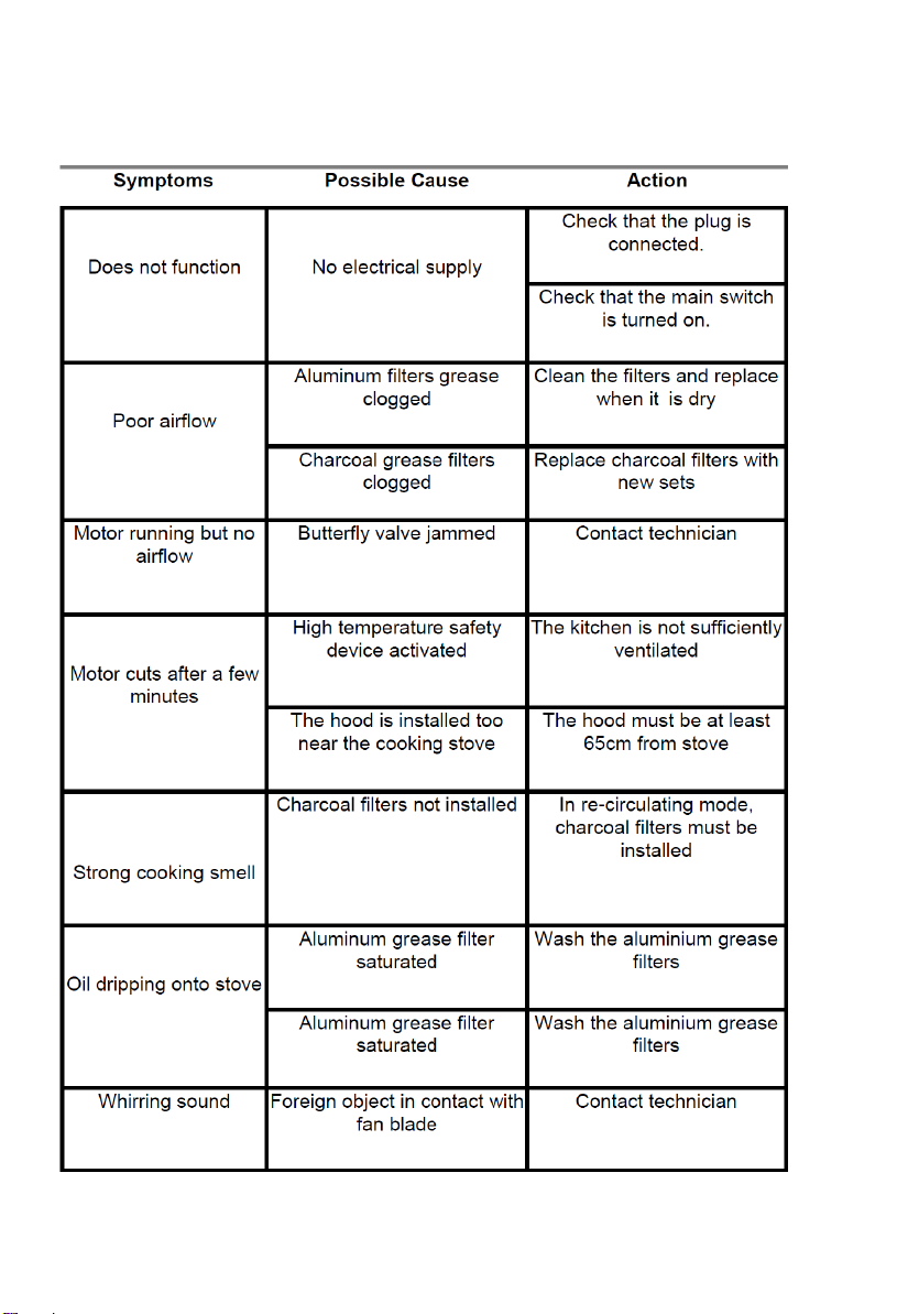
TROUBLE SHOOTING
This manual suits for next models
1
Table of contents
Other diLUSSO Ventilation Hood manuals


Popular Ventilation Hood manuals by other brands


ELICA
ELICA Missy PRF0004024A Instruction on mounting and use

FABER S.p.A.
FABER S.p.A. STRIP SMART EV8 manual

Electrolux
Electrolux DXK6000 user manual

Fisher & Paykel
Fisher & Paykel HC60DCEXB3 user guide

Frigidaire
Frigidaire FHPC4260LS Product specifications

KOBE
KOBE CH2230SQ Installation instructions and operation manual