AURORA UPC ZS ZONE SENSORS INSTALLATION GUIDE
What are ZS sensors? ................................................................................................................................................. 1
ZS zone sensors........................................................................................................................................................... 8
ZS duct sensors..........................................................................................................................................................16
ZS pipe clamp-on temperature sensor ....................................................................................................................24
ZS immersion temperature sensor ..........................................................................................................................28
ZS outdoor air temperature sensors........................................................................................................................33
To format a ZS Sensor.............................................................................................................................................
.
..39
Document revision history ........................................................................................................................................40
Contents
What are ZS sensors? .............................................................................................................................................
.
Rnet configuration............................................................................................................................................
Rnet wiring specifications ...............................................................................................................................
Power requirements.........................................................................................................................................
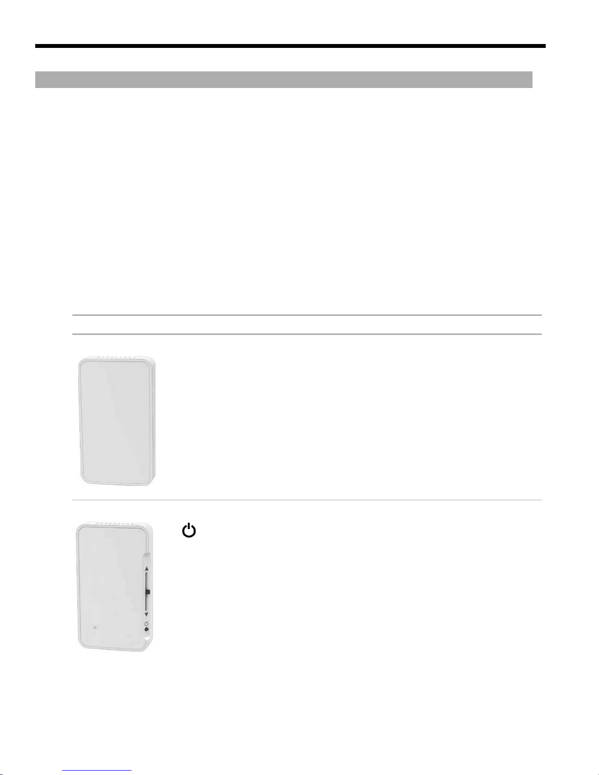
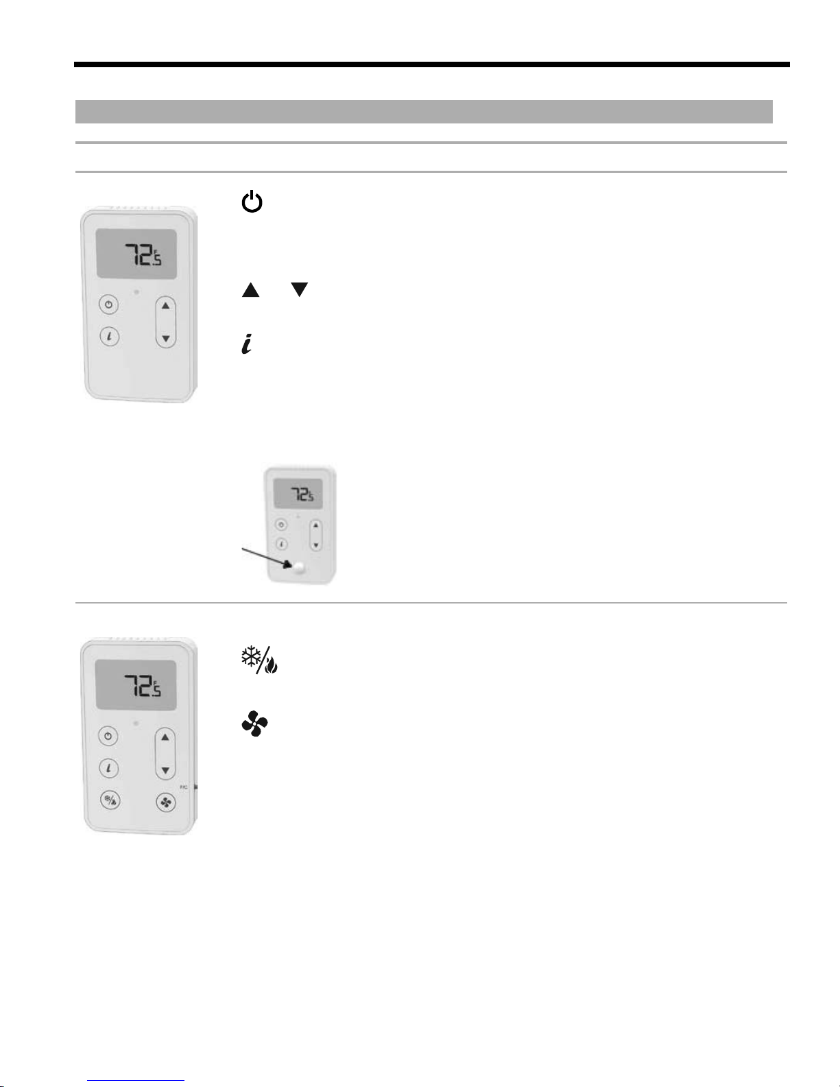
ZS zone sensors.......................................................................................................................................................
.
Specifications for ZS zone sensors ................................................................................................................
CO2 sensor installation....................................................................................................................................
Motion sensor installation...............................................................................................................................
To address a ZS zone sensor ..........................................................................................................................
To wire and mount a ZS zone sensor ............................................................................................................
To communicate through a ZS zone sensor's local access port ...............................................................
.
ZS duct sensors..........................................................................................................................................................16
ZS pipe clamp-on temperature sensor ....................................................................................................................24
ZS immersion temperature sensor ..........................................................................................................................28
ZS outdoor air temperature sensors........................................................................................................................33
To format a ZS Sensor...............................................................................................................................................39
Document revision history ........................................................................................................................................40
4
6
7
8
9
9
11
11
11
12
13
15