Firecraft FBK-100 User manual
NOTE: DIAGRAMS & ILLUSTRATIONS NOT TO SCALE. 1
GENERAL INFORMATION
BLOWER KITS
FBK-100 AND FBK-200
These blower kits may be used with various models of fireplaces. The
FBK-100 blower kit is used when wall-mounted ON/OFF blower switch
is desired, and the FBK-200 when wall-mounted variable speed blower
control is desired. The blower is installed beneath the firebox. Room air
is drawn in through the bottom area of the fireplace, heated as it passes
across the firebox, and discharged through the upper panel/louver area
at the top of the fireplace. Kit FBK-100 contains one blower, two Velcro
strips and these instructions. Kit FBK-200 contains one blower, one
speed control switch, two Velcro strips and these instructions.
Note: Velcro strips are for use in Step 6 D on page 2 only.
See Installation Instructions on the following pages:
Wood Fireplaces - See Pages 1-3.
D-Vent and B-Vent Fireplaces - See Pages 1-3.
Universal Vent Free Fireplaces - See Page 4.
HEARTH PRODUCTS
KITS AND ACCESSORIES
INSTALLATION INSTRUCTIONS FOR BLOWER KITS
FBK-100 (CATALOG NO. 80L84) AND FBK-200 (CATALOG NO. 80L85)
FOR USE WITH FIREPLACES
Step 1. Turn off the fireplace and allow it to cool before proceeding.
Step 2. If the appliance is connected to 120 volt power, disconnect
the power.
Step 3. If unit is a gas fireplace, shut off the gas supply to the fireplace.
Step 4. Gas fireplaces -
Open the lower panel (clean face models) or louver assembly (louvered
models) by pushing in simultaneously the left and right side of the panel
or louver assembly.
On Merit Fireplaces
, remove the bottom panel or louvers by removing the
screw at each end of the panel or louvers, retain the end spacers, and then
pull the panel or the louvers from the unit.
On Elite-2 Fireplaces
, remove the bottom door (panel or louvers) by
sliding the hinge pin, located at the door’s left side, to the right until it
disengages from the left corner post hole. Pull the door diagonally to the
left, away from the fireplace.
INSTALLATION INSTRUCTIONS
Figure 1
Note:In Universal Vent-Free fireplace applications refer to the installation
instructions packaged with the fireplace for additional information.
750,028M
REV. E 03/2006
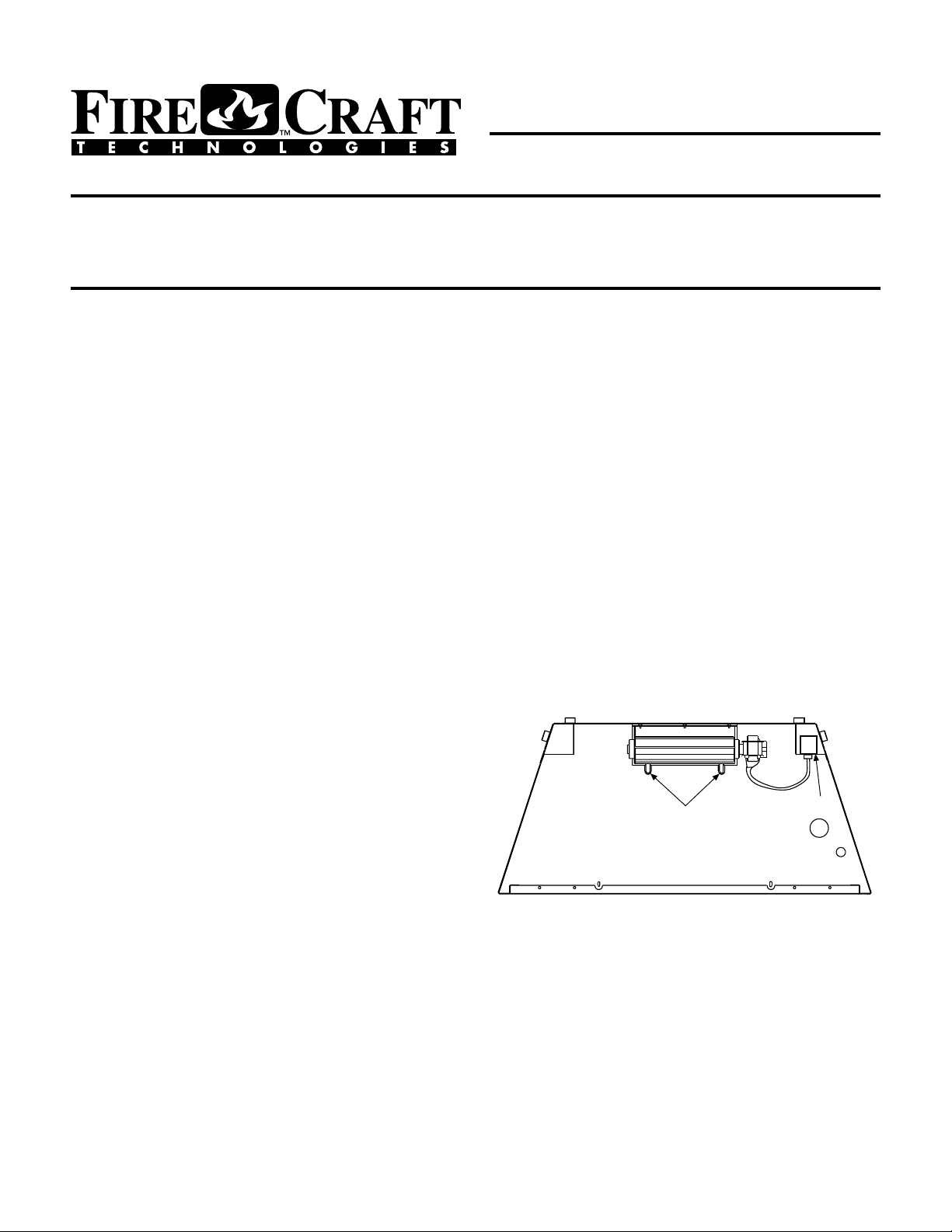
BLOWER
MOUNTING
TABS
BLOWER JUNCTION BOX
ELECTRICAL OUTLET
BLOWER INSTALLATION
FRONT-OPEN DIRECT VENT AND B-VENT GAS FIREPLACE
Wood-burning fireplaces -
When equipped with a louver panel -
Push the two fireplace opening
screens toward the middle of the unit to expose the louver panel retaining
screwateachendofthepanel.Removetheretainingscrewsandthenpull
the panel from the unit.
Whenequippedwithagrille-
Removethebottomgrillebyliftingit up near
its outer support rods. It must be lifted high enough to clear the support
rod retaining holes located in the cabinet bottom flange. Then pull the
bottom of the grille away from the fireplace and set the grille aside.
Step 5. Elite-2 Series Gas Fireplaces - Remove the modesty panel as
follows: lift the modesty panel by the tab on the panel’s right end, pull the
right end of the panel away from cabinet and then pull the panel diagonally
out of the corner post slots on the left side of the unit. Remove the modesty
panel carefully, so that none of the wires become loose or disconnected.
Step 6. A - Gas Fireplaces - Front-open direct vent and B-vent units -
Slide the blower assembly through the front opening to the middle rear
area of the cabinet base. Position the blower assembly so that the tabs
(located on the cabinet base) are seated in the notches of the blower bracket.
Then bend the tabs over to secure the blower assembly
(Figure 1 )
.
NOTE: DIAGRAMS & ILLUSTRATIONS NOT TO SCALE.
2
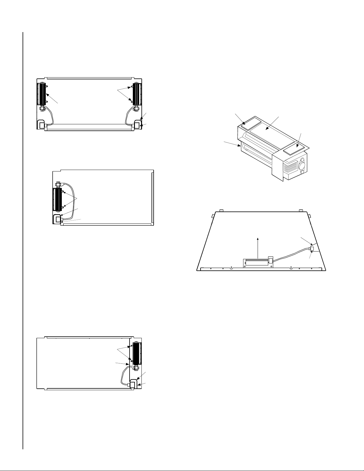
Step 6. D - Wood-burning fireplaces (other than vent-free) -
Place the two mating halves of each of the two Velcro sections together.
Peel the backing from one side of both of the mating pairs and stick the
pairs to the back of the blower housing as shown in
Figure 5
.
Wipe the inside surface of the bottom of the unit of any excess oil or debris.
Peel the backing from the other side of the two mated Velcro strips.
Slide the blower assembly through the front opening of the unit (avoiding
any contact between the sticky blower bottom and the cabinet). Position
the blower assembly as shown in
Figure 6
, pressing firmly down on the
blower in order to provide a positive blower to base attachment.
Step 6. C - Gas Fireplaces - Multi-open vent-free units -
Open all remaining bottom hinged-panels. Remove the blower shield
located across the inside right section of the unit.
See Figure 4
. Also
refer to the installation instructions packaged with the fireplace for ad-
ditional information on shield removal. Slide the blower assembly
through the closest opening to the flue side of the cabinet base. Posi-
tion the blower assembly so that the tabs (located on the cabinet base)
are seated in the notches of the blower bracket. Bend the tabs over to
secure the blower assembly. Reinstall the blower shield with the blower
cord routed to the electrical outlet.
Figure 4
Figure 5
Figure 6
BLOWER MOUNTING TABS
BLOWER
JUNCTION
BOX
ELECTRICAL
OUTLET
BLOWER INSTALLATION
MULTI-OPEN CATALYST AND VENT-FREE GAS FIREPLACE
(See-through, Peninsula)
BLOWER SHIELD
BLOWER
BLOWER SECURED
TO BASE WITH
VELCRO STRIPS
JUNCTION BOX
ELECTRICAL OUTLET
AIR FLOW
DIRECTION
BLOWER CENTERED SIDE TO SIDE AT THE FRONT OF THE UNIT
BLOWER INSTALLATION WOOD-BURNING FIREPLACES
(OTHER THAN VENT-FREE)
INSTALLING VELCRO STRIPS TO BLOWER BASE
MATING PAIR OF VELCRO STRIPS
BLOWER
GASKET
MATING PAIR
OF VELCRO
STRIPS
Figure 3
BLOWER
JUNCTION BOX
ELECTRICAL OUTLET
BLOWER INSTALLATION
MULTI-OPEN DIRECT VENT GAS FIREPLACE
(Corner Right)
BLOWER MOUNTING TABS
Step 6. B - Gas Fireplaces - Multi-open direct vent units -
Open all remaining bottom hinged-panels. Slide the blower assembly
through the closest opening to the flue side of the cabinet base. Position
the blower assembly so that the tabs (located on the cabinet base) are
seated in the notches of the blower bracket. Bend the tabs over to secure
the blower assembly.
See Figure 2 or 3
.
Figure 2
BLOWER
MOUNTING
TABS
BLOWER
JUNCTION
BOX
ELECTRICAL
OUTLET
BLOWER INSTALLATION
MULTI-OPEN DIRECT VENT GAS FIREPLACE
(See-through, Peninsula, Corner Left)
BLOWER MOUNTED
HERE ON MPD35ST
MODEL
Step 7. Install the field-provided ON/OFF switch (FBK-100 Kits) or
the kit-provided variable speed control (FBK-200 Kits) in a convenient
location on a wall, near the fireplace.
Step 8. Route a 3-wire, 120Vac power line to the ON/OFF switch (FBK-
100 kits) or variable speed control (FBK-200 kits) as shown in
Figure 7.
Then route the wires to the unit’s junction box. Remove the receptacle by
removing the two securing screws. Connect the supply wires to the
receptacleas shown in
Figure7,
ensuring that thepolarity(as determined
by the colors of the wires) is exactly as shown. Reinstall the receptacle.

NOTE: DIAGRAMS & ILLUSTRATIONS NOT TO SCALE. 3
Step 9. Plug the blower cord into the top receptacle.
Step 10. Elite-2 Series Gas Fireplaces - Reinstall the modesty panel.
Reinstall the modesty panel carefully, so that none of the wires become
loose or disconnected.
Step 11. Gas fireplaces -
Reinstall the bottom panel or louver assembly.
Wood-burning fireplaces -
Reinstall the bottom louver panel or grille.
Step 12. Restore the electrical power to the unit.
Figure 7
IMPORTANT: Ground lead must be connected to the green screw
located on the junction box. Failure to do so will prevent the
appliance from operating. The appliance must be electrically
grounded in accordance with local codes or, in the absence of local
codes, the National Electrical Code, ANSI/NFPA 70-(latest edition).
(In Canada, the current CSA C22-1 Canadian Electrical Code.)
Step 13. Start the fireplace by following the procedure indicated in
the lighting instructions section of the Homeowner’s Care and Oper-
ating Instructions manual supplied with the fireplace.
Step 14. Check the start up and shutdown, and the running operation of
the blower. If the variable speed control is being used, check its operation.
JUNCTION BOX
Factory Wired
Field Wired
NEUTRAL SIDE OF RECEPTACLE HOT SIDE OF RECEPTACLE
Tab intact
120 VAC BLACK
NEUTRAL WHITE
GROUND GREEN
Black
Red
BLOWER
Green Ground Screw
120V, 60HZ, 1PH BLOWER CONTROL CIRCUIT WIRING (Direct Vent Appliances)
Plug blower into top receptacle
BOTTOM RECEPTACLE
If any of the original wire as supplied must be replaced, it must be replaced with type AWM 105 degree C - 14 gauge wire.
*Wall-mounted ON/OFF Blower Switch
or Speed Control
*ON/OFF Blower Switch is field provided when using
FBK-100 kit;Speed Control is provided in FBK-200 kit.
Break Tab Off
TOP RECEPTACLE
Figure 8
JUNCTION BOX
Factory Wired
Field Wired
NEUTRAL SIDE OF RECEPTACLE HOT SIDE OF RECEPTACLE
120 VAC BLACK
NEUTRAL WHITE
GROUND GREEN
Black
BLOWER
Green Ground Screw
120V, 60HZ, 1PH BLOWER CONTROL CIRCUIT WIRING (Wood And B-Vent Appliances)
Plug blower into receptacle
BOTTOM RECEPTACLE
If any of the original wire as supplied must be replaced, it must be replaced with type AWM 105 degree C - 14 gauge wire.
Wall-mounted ON/OFF
Blower Switch or Speed Control
*ON/OFF Blower Switch is field provided when using
FBK-100 kit;Speed Control is provided in FBK-200 kit.

NOTE: DIAGRAMS & ILLUSTRATIONS NOT TO SCALE.
4
Printed in U.S.A. © 2001 by Lennox Hearth Products
P/N 750,028M REV. E 03/2006
The manufacturer reserves the right to make changes at any time, without notice, in design,
materials, specifications, prices and also to discontinue colors, styles and products.
Consult your local distributor for fireplace code information.
1110 West Taft Avenue - Orange, CA 92865
Models UVFRC-4228, UVFRC-4228-H
UVFRC-3628 and UVFRC-3628-H :
Reinstall the bottom refractory panel that was
removed on
Step 1
(see
Figure 9 )
.
Models UVF-36:
Reinstall the blower access panel that was
removed on
Step 1
(see
Figure 10 )
.
Universal Vent Free Fireboxes
Installation Instructions -
FBK-100 or FBK 200 Blower Kits
JBK Junction Box Kit
Step 1. Follow the instructions below for the
model you are installing:
Models UVFRC-4228, UVFRC-4228-H,
UVFRC-3628 and UVFRC-3628-H:
Lift out the bottom refractory panel
(see
Figure 9 )
.
Models UVF-36 - Using a screwdriver remove
the screw from the blower access panel as
shown in
Figure 10.
Slide the panel to the
right until the flange clears the opening. Re-
move the panel and set aside.
Step 2. Remove the rectangular knock-out
(for J-Box) on the right side of the unit.
Install the junction box and electrical outlet
below the firebox floor into the rectangular
opening on the right side cabinet panel
where you removed the knock-out (
see
Figures 11 & 12
). The junction box/
electrical kit is sold separately.
Note:
Pass the wires through the hole, then
squeeze the J-Box flanges together to fit into
opening.
Step 3. Loosely tie a knot in the power cord
to take up slack (see
Figure 13 )
.
Step 4. Locate the tabs shown in
Figure 14.
Position the blower assembly so that the
tabs (located on the cabinet base) are seated
in the notches of the blower bracket. Bend
the tabs over to secure the blower assembly
(see
Figure 15 )
.
Step 5. Plug blower power cord into the
J-Box electrical outlet.
Step 6. Connect electrical outlet and switch
wires to the power supply; 3-wire, 120 VAC,
60 Hz, 1 ph power supply (see
Figure 8 )
.
FBK-100 Kits - Install a field-provided (or P/N
85L87) ON/OFF wall switch in a convenient
location on a wall, near the fireplace.
FBK-200 Kits - Install the kit-provided vari-
able speed control (rheostat) in a convenient
location on a wall, near the fireplace.
Step 7. Follow the instructions that follow
for the model you are installing:
Lift Out Bottom Refractory Panel
Models
UVFRC-4228, UVFRC-4228-H,
UVFRC-3628 and UVFRC-3628-H
Bottom
Refractory
Panel
Figure 9
Figure 10
Remove Screw, Then Lift Out Blower Access Panel
(Model UVF-36)
Firebox Floor Remove Screw
Blower
Access
Panel
Figure 11
(Model UVFRC-4228 Shown)
Firebox
Floor
J-Box Flange
Install Into Side Wall Rectangular Opening
J-Box & Electrical Outlet
J-Box And
Electrical Outlet
J-Box Flanges
Wires
Right Outside Cabinet Panel
Figure 12
Figure 13
Figure 14
Figure 15
NOTE: DIAGRAMS & ILLUSTRATIONS NOT TO SCALE.
Loose Knot In Power
Cord To Take Up Slack
Firebox
Floor
Model UVFRC-4228 Shown
Locating Tabs
Cabinet Base
Model UVFRC-4228 Shown
Bend Locating Tabs Over
(Into Notches)
Model UVFRC-4228 Shown
This manual suits for next models
3


