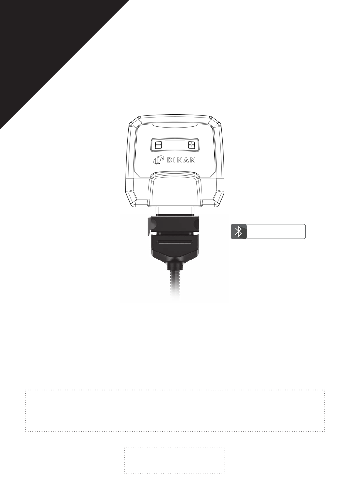
Dinan Dinantronics X User manual
PLEASE
READ BEFORE
STARTING
INSTALLATION!
User Manual
Performance upgrade
+APP-CONTROL
27: ; N20

1 Scope of Delivery .....................................................................................................................................................................................................A
2 Overview of the performance upgrade .............................................................................................................................................................. B
3 Installation ................................................................................................................................................................................................................ C
4 Fine tuning ................................................................................................................................................................................................................ D
5 Trouble Shooting.......................................................................................................................................................................................................E
Contents
Overview and explanation of symbols
Warnings and important information – please read!
General information on installation and use
Tips to assist installation and use

(1) Picture may differ from delivered product.
A
B
C
Performance Upgrade
calibrated specifically for your
vehicle
Wiring harness
automobile-grade, compatible
with your vehicle (1)
Cable ties
2 x long cable ties
3 x short cable ties
Deactivation plug
D
User Manual
E
A
1 Scope of Delivery
A
C
E
F
B
A
B
C
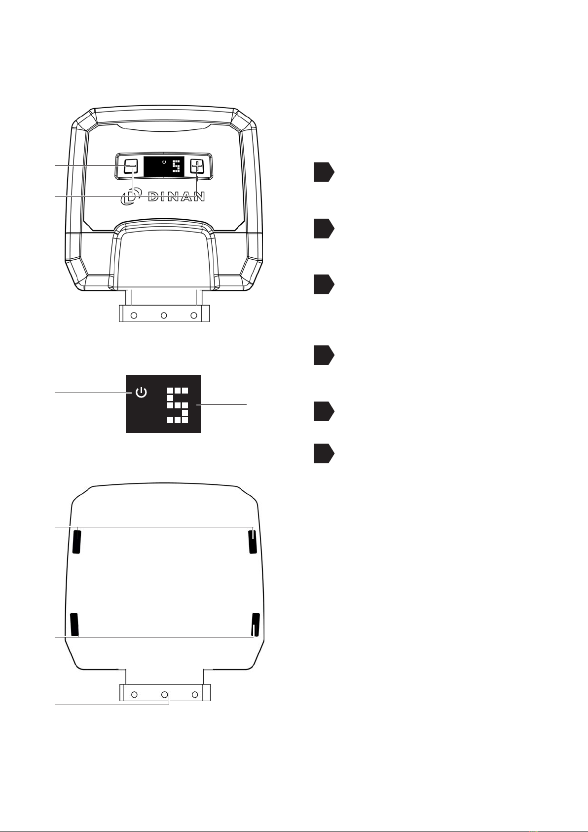
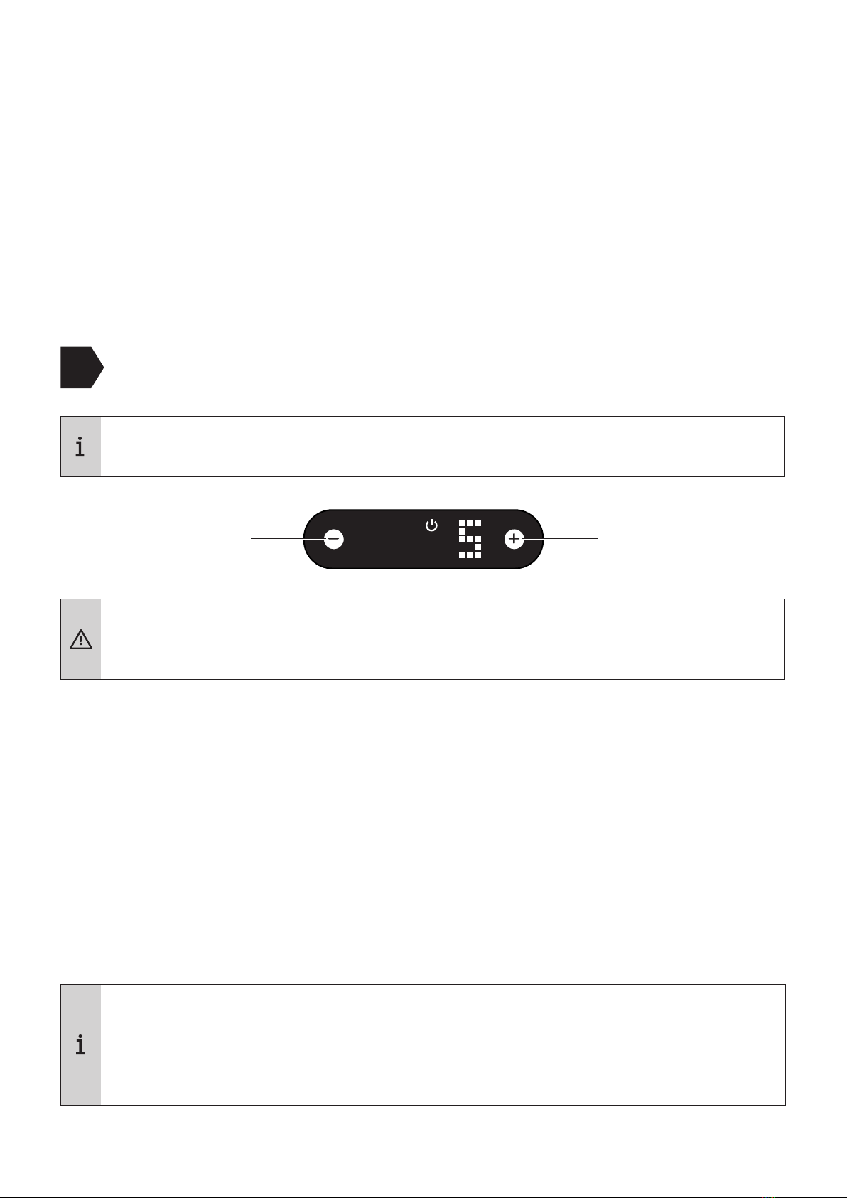
Digital User Interface for controlling
the .
+/- buttons for changing the mapping
(see Fine tuning)
Power ON light; lights only when the
vehicle ignition is on and power is
being supplied to the RaceChip.
Display showing mapping selected
(see Fine tuning).
D
lot for
E
FCI plug for connecting to the vehicle’s
wiring.
F
B
A
B
C
D
F
E
E
2 Overview of the performance upgrade

C
3 Installation
Step 1 of 8
1
2
– Preparation
efore nang e nng mode peae a for or engne o coo don
ere ere a r of anng rn
Open your vehicle’s bonnet, and close and lock the doors.
Wait about 10 minutes before starting Step 2, as all current consumers must have
switched themselves off.
Generally speaking, you do not require special tools to perform the installation. If you
need a tool, we will tell you when you get to the relevant step in these instructions. You
will probably find wire cutters useful for clipping off the loose ends of cable ties.
• For cars with “Keyless Go”: after locking the car, place the key out of signal range
(about 10 m from the car).
• If an alarm system is fitted disable the alarm before starting installation.
• Some cars will not lock completely if the bonnet is open and electrical consumers
are still active. If this is the case with your car, push the bonnet catch over manually,
lock the car again and wait ca. minutes. hen you have finished the installation,
do not forget to release the catch again by pulling the bonnet release lever.
•f you have any uestions or difficulties during the installation, please refer to
for hints and tips.

C
3 Installation
•Remove the engine cover and place it next to the car. You may have to jiggle the cover
slightly to release it from the holding clips.
– Removing the engine coverStep 2 of 8

C
3 Installation
1
A
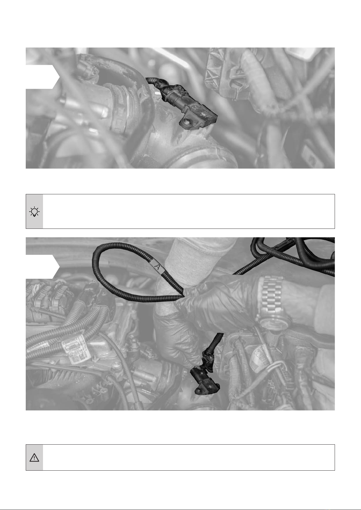
Step 3 of 8 – Connection to turbo boost pressure sensor
•First locate the turbo boost pressure sensor connection in your engine bay.
Turbo boost pressure sensor
Turbo boost
pressure sensor
Setup illustration
Cable with disconnected
stock plug
Cable from the
tuning module.
Turbo boost pressure sensor
C
3 Installation
•Disconnect the plug from the turbo boost pressure sensor
f you experience difficulties disconnecting the turbo boost pressure sensor, see
Detaching the Connector Correctly (separate document) for assistance.
Make sure that the plug’s locking clip engages again. You should hear a sharp CLICK.
• Now connect the end of the wiring harness marked “A” to the
disconnectedconnector and the other end to the sensor.
2
3

C
3 Installation
1
B
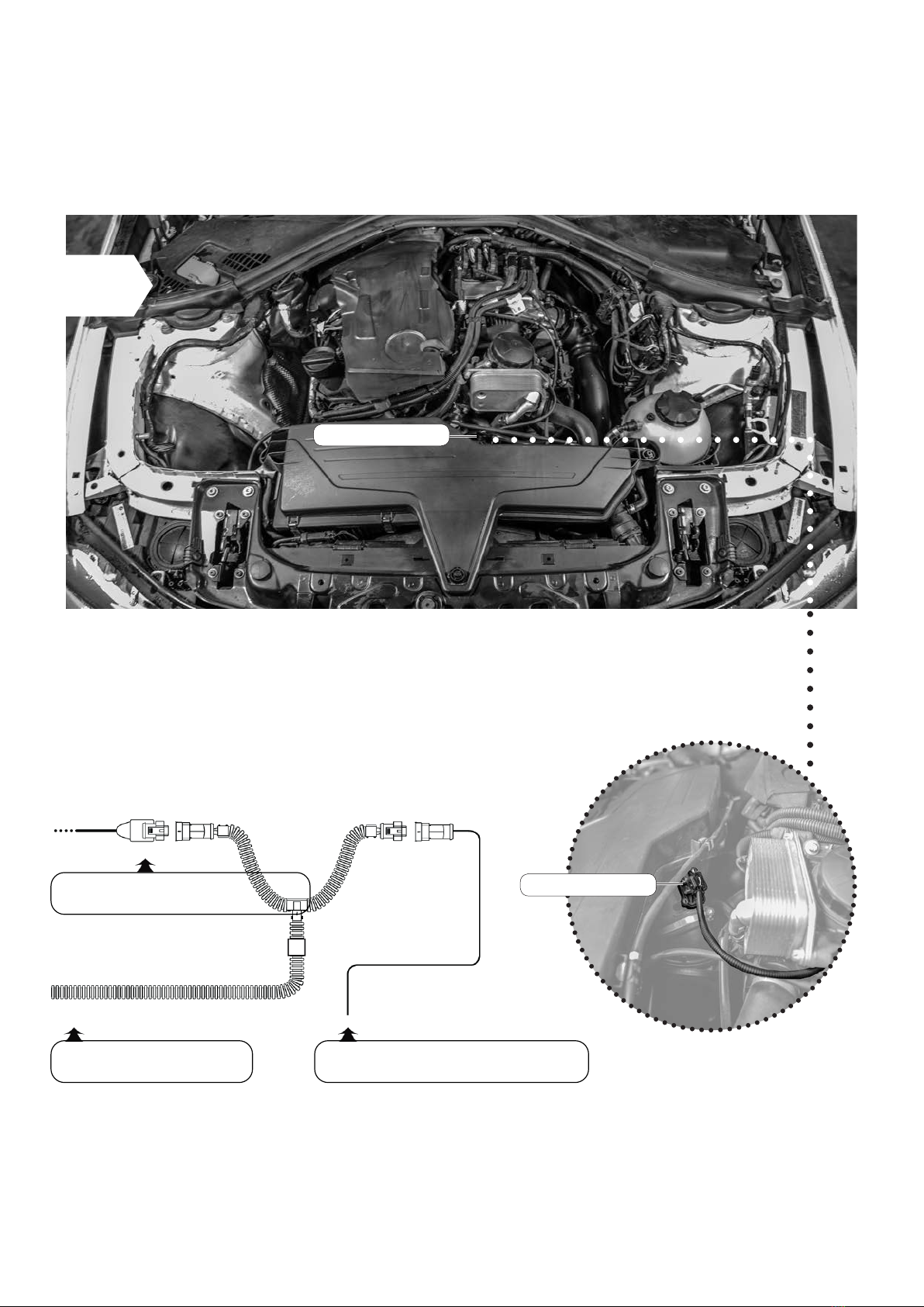
Step 4 of 8 – Connection to manifold absolute pressure sensor
Manifold absolute
pressure connection
Manifold absolute
pressure connection
Manifold absolute
pressure connection
•Once the connection to the turbo boost pressure is complete, it is time to make the
connection to the manifold absolute pressure sensor.
Setup illustration
Cable with disconnected
stock plug
Cable from the
tuning module

C
3 Installation
Make sure that the plug’s locking clip engages again. You should hear a sharp CLICK.
• Now connect the end of the wiring harness marked “B” to the disconnected
connector and the other end to the sensor.
f you experience difficulties disconnecting the manifold absolute pressure sensor, see
Detaching the Connector Correctly (separate document) for assistance.
•Disconnect the plug from the manifold absolute pressure sensor.
2
3
C
3 Installation
1
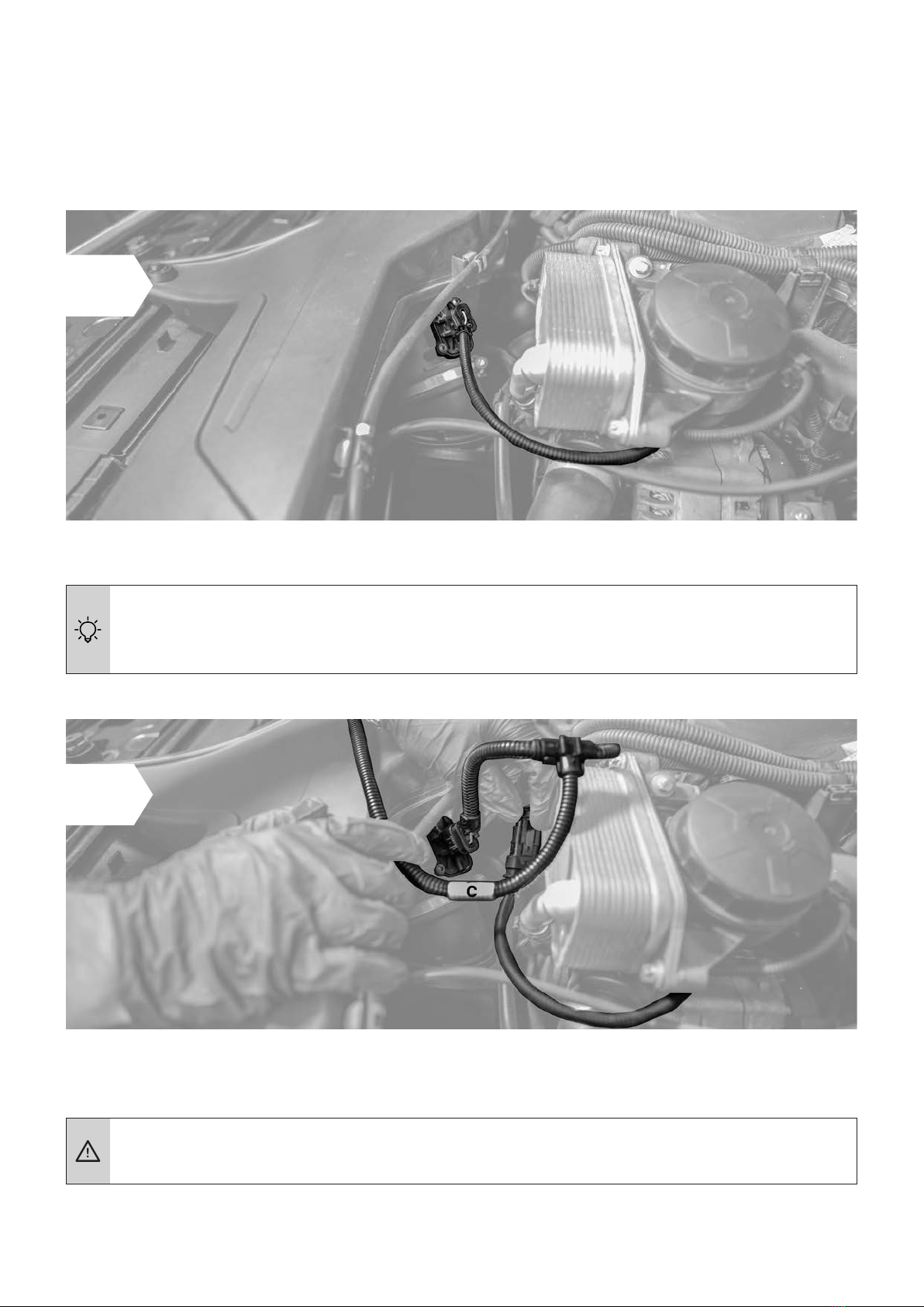
Step 5 of 8 – Connection to air ow sensor
Air ow sensor
Air ow sensor
•irst locate the air ow sensor connection in your engine bay.
Setup illustration
Manifold absolute pressure connection
Cable from the tuning module Cable with disconnected stock connector
C
3 Installation
Make sure that the plug’s locking clip engages again. You should hear a sharp CLICK.
• Now connect the end of the wiring harness marked “C” to the
disconnectedconnector and the other end to the sensor.
f you experience difficulties disconnecting the air ow sensor, see
Detaching the Connector Correctly (separate document) for assistance.
•isconnect the plug from the air ow sensor.
2
3

C
2
1
3
Disconnect the deactivation plug
from the wiring harness Connect the nng ode
Carrying out function test
•Position the and the wiring harness safely in the engine bay. o
not fi xanything in place yet.
• Switch the ignition on. DO NOT start the engine.
• Check for the following:
- Control lights on the dashboard light up and go out as normal.
-he Power lamp on the lights up see Overview).
• If all the above happens, you can start the engine. It should start as normal and
should react to the throttle when idling.
• Switch off the engine and ignition.
• If your car will not start as normal, please refer to Trouble Shooting for hints and tips.
• Our Customer Service is of course always ready to help. See Contact for details.
33 II nn ss tt aa ll ll aa tt ii oo nn
SS t t ee pp 66 -- CC oo nn nn ee cc t t ii nn gg aa nn dd f f ii r r ss t t f f uu nn cc t t ii oo nn t t ee ss t t
If the Digital User Interface lit up as soon as it was connected, this means that there
was still power in thesystem during the installation.
In some cases, this can lead to an error message during the first function test. Please
refer to Trouble Shooting for a solution.

C
•efore he in place in the engine bay, ensure that the wiring harness can
alsobe routed and securely without putting it under excessive tension.
Wiring harness
Tuning Module
33 II nn ss tt aa ll ll aa tt ii oo nn
SStteepp 77 -- FFiixxiinngg tthhee ttuunniinngg mmoodduullee aanndd wwiirriinngg hhaarrnneessss

C
3 Installation
•Route the cable along a suitable path (for example, along existing wiring harness) and then
fasten it using the supplied cable tie.
• When selecting a fastening point, make sure that the is protected from
expo-sure to water, heat, and vibrations.
• Do not wrap the in an airtight bag as this can lead to a built up of
condensa-tion.
• Do not route the cable in areas in your vehicle that become overly hot during operation
(e.g. the exhaust system, turbocharger, etc.).
• Do not route the cable along movable parts.
• Never fasten the cable onto hoses (e.g. a brake hose) as this could result in abrasion.
Step 7 of 7 – Finishing the installation in the engine bay
• Re-attach the cover of your engine and close the bonnet.
• The basic installation is now complete and the can be used
(in the SPORT tuning stage if you have app control).
• Take your car for a test drive. If you have any questions, do not hesitate to contact our
Customer Service department (see Contact for details).

3 Installation
Last step – Pair the tuning module with your smartphone
Download the free app
.
Switch on the ignition of your car. Do not start the engine.
Open the app.
ith opening the app for the first time,
the installation dialogue for chip tuning by tuning module
is shown. Touch ADDPRODUCT and follow the
instructions given by your smartphone.
ccording to your operating system Android and Apple, the steps for connecting the tuning
module and your smartphone may vary. Please fi nd the most important steps below. n general,
you should follow the instructions given by your smartphone for the connection.
ctivate the luetooth function of your smartphone.
•he connection between the tuning module and your smartphone is set up in the last
step of the installation process.
•he tuning module is fully functional even if there is no connection to a smartphone
running the Tuning Pro app.
1
2
4
5
3
C

3 Installation
6ou can enter the serial number by hand touch MANUALLY) or with the barcode scanner
of the camera touch
ou can enter the serial number by hand touch
. onfi rm the entry with NEXT.
7s soon as the connection is set up, the installation is completed.
Having trouble with connecting your tuning module and your phone’s Bluetooth?
ollow these steps one by one until the pairing is complete
Check that the car’s ignition is switched on.
heck that the luetooth function on your smartphone is fully activated.
heck to see if the tuning modules luetooth connection is active see Overview
of the tuning module. f the luetooth symbol is ashing or not lit, please
contact our customer service.
Deactivate and then re-activate the Bluetooth connection. Check if the tuning
module and your phone will pair now.
Re-start the Tuning Pro app.
o to your smartphones settings and view all discoverable luetooth devices. f
your tuning module D is not visible, please contact our
customer service.
Example:
he 3-digit serial number is located on the
connector of the tuning module. he luetooth
P consists of the last 6 digits of the serial
number.
Serial number
Bluetooth-PIN
C
4 Fine tuning
he igital ser nterface of the see Overview lets you carry out the ine
tuning yourself to get the best from your -enhanced engine.
ine tuning may be necessary if the following occurs
AEngine idles more roughly than in stock tune.
The Fine tuning mappings can be changed using the +/- buttons only when the
ignition is switched on but without the engine running.
•apping 5 is the factory setting.
•irst activate apping 1.
•ake your car for a test drive. f the engine performs as smoothly as you want, i.e. no
hesitation or knocking, please activate apping 2 and go for another test drive.
•f the engine still performs as smoothly as you want, repeat the previous step.
•f the engine does not perform as smoothly as you want with one of the mappings, go back
to the previous mapping this is the right one for your engine.
f your engine does not run smoothly with any of the mappings or if the engine control
light is permanently on after making all the adustments and after switching the
ignition off and waiting minutes, please contact our ustomer ervice see Contact
for details.
ngine runs roughly, knocks or pinks under load, or the engine warning light comes on.
D
Mapping step -1 Mapping step +1

4 Fine tuning
Making the enhanced performance more noticeable
The Fine tuning mappings can be changed using the +/- buttons only when the
ignition is switched on but without the engine running.
•apping 5 is the factory setting.
•irst activate apping 6.
•ake your car for a test drive. ctivate apping 7 only if you do not experience the enhanced
performance strongly enough.
•f the engine does not perform as smoothly as you want, activate the next mapping down
the scale e.g. from 6 to 5.
•Mapping 0 puts the engine into stock tune with the installed.
•ou can also use the deactivation plug to return you car to stock tune without
having to remove the wiring harness. n order to use the deactivation plug, you need
to remove the from the wiring harness connector and replace it with
thedeactivation plug.
•
see Step 1.
f the driver does not experience the extra performance, it means the driver cannot feel
the difference from stock tuning.
B
D
Mapping step -1 Mapping step +1

5 Trouble Shooting
f the does not function as it should, you can find some initial assistance here. f
the suggestions here do not solve the problem, please contact our ustomer ervice see
Contact.
Description of problem What to do
No extra performance
or performance not
noticeable enough
am not satisfied with the
performance level of my
vehicle.
•ou can find detailed instructions on how to make the extra
performance more noticeable in Fine tuning section B.
Knocking/ rattling
he engine knocks or
rattles diesel engine
more under load. t runs
less smoothly than in
stock tune.
•f you have the impression that your engine knocks or rattles
more than in stock tune, please take the car for a few test
drives to be sure that your first impression was right. n the
test drive, pay special attention to the engines under
load the only works then.
•f your first impression was right, you can find detailed
instructions on how to make the engine run smoothly again in
Fine tuning section A .
•f the knockingrattling is very noticeable, you can carry out
the steps described in Fine tuning immediately.
Jolting
With the
•ou can find detailed instructions on how to make the engine
run smoothly again in Fine tuning section A.
•f that does not cure the problem, please contact our
ustomer ervice if you can describe the circumstances
when the problem occurs, our ustomer ervice can make
further adustments.
Quality of the gear shift
reduced
•elect the next lowest mapping
see Fine tuning, section A. epeat this procedure until you
are happy with the gear shifting.
•f that does not cure the problem, please contact our
ustomer ervice if you can describe the circumstances
when the problem occurs, our ustomer ervice can make
further adustments.
E
This manual suits for next models
1
Table of contents


