Haldex EB+ CAN Hub User manual

CAN Hub
Innovative Vehicle Solutions
INSTALLATION GUIDEINSTALLATION GUIDE

EB+ CAN Hub Installation
Guide
2Innovative Vehicle Solutions 2020
This manual has been designed to assist personnel in
satisfactory installation of Haldex EB+ CAN Hub onto
trailers. The intention has been to illustrate various
aspects of the installation. It is expected that this
manual will be in possession of the appropriate person
throughout their ‘training’ and ‘experience’ and that
the manual will be used as:
a) A teaching aid following supervision of a Haldex
engineer.
b) A reminder of the correct procedure of Haldex
EB+ CAN Hub installation.
›Use appropriate spare-parts documentation when
obtaining spare parts
›Use only genuine Haldex parts in repairs
›Due to continuous development the right is reserved
to alter the specification without notice
›No legal rights can be derived from the contents of
the manual
›Duplication, translation and reprinting are prohibited
without permission from Haldex Brake Products
Notes on the use of this manual

EB+ CAN Hub
Installation
Guide
3
2020 Innovative Vehicle Solutions
Introduction............................................................... 4
EB+ CAN Hub versions............................................... 6
External pressure sensor........................................... 10
Warning lamp .......................................................... 13
Dimension and identification.................................... 15
Chassis installation ................................................... 16
Excess cable............................................................. 22
Painting ................................................................... 23
Welding................................................................... 24
Configuring EB+ CAN Hub....................................... 25
Software update limitations ..................................... 42
Customer drawing ................................................... 43
Part reference ..........................................................46
Contents

EB+ CAN Hub Installation
Guide
4Innovative Vehicle Solutions 2020
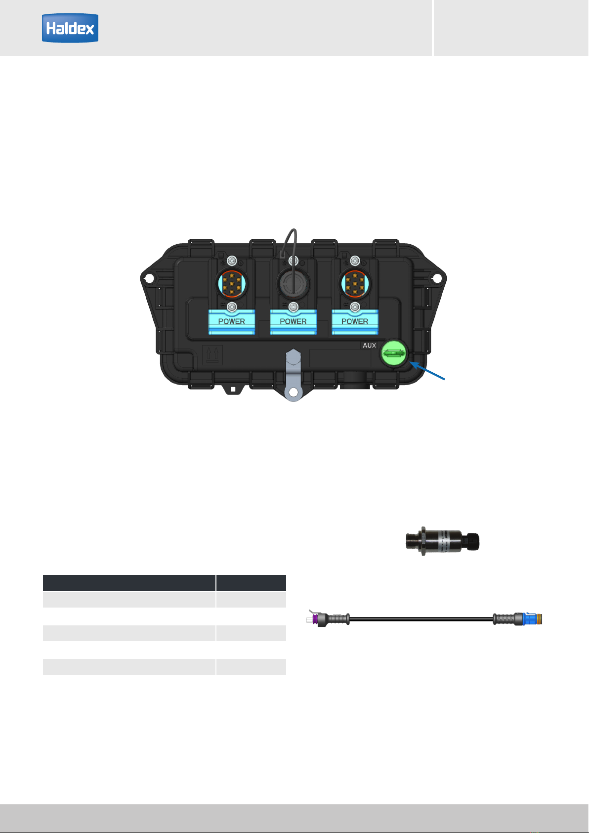
EB+ CAN HUB is an ISO 11992 router for 12 / 24 V EB+ EBS systems. It has three EB+ Power A (ISO 7638)
connectors, sharing power and lamp connections but each having a separate ISO 11992 node and an input to
connect an external pressure sensor for a commercial vehicle not equipped with ISO 11992 (i.e. Truck with ABS
system only).
EB+ CAN Hub requires Haldex EBS (Gen3 with E741 or later software) on the same trailer, in order that
configuration and diagnostics is performed correctly. In road trains EB+ CAN Hub works with any EBS meeting the
requirements of ISO 11992, which includes all trailers with UN R13 approval.
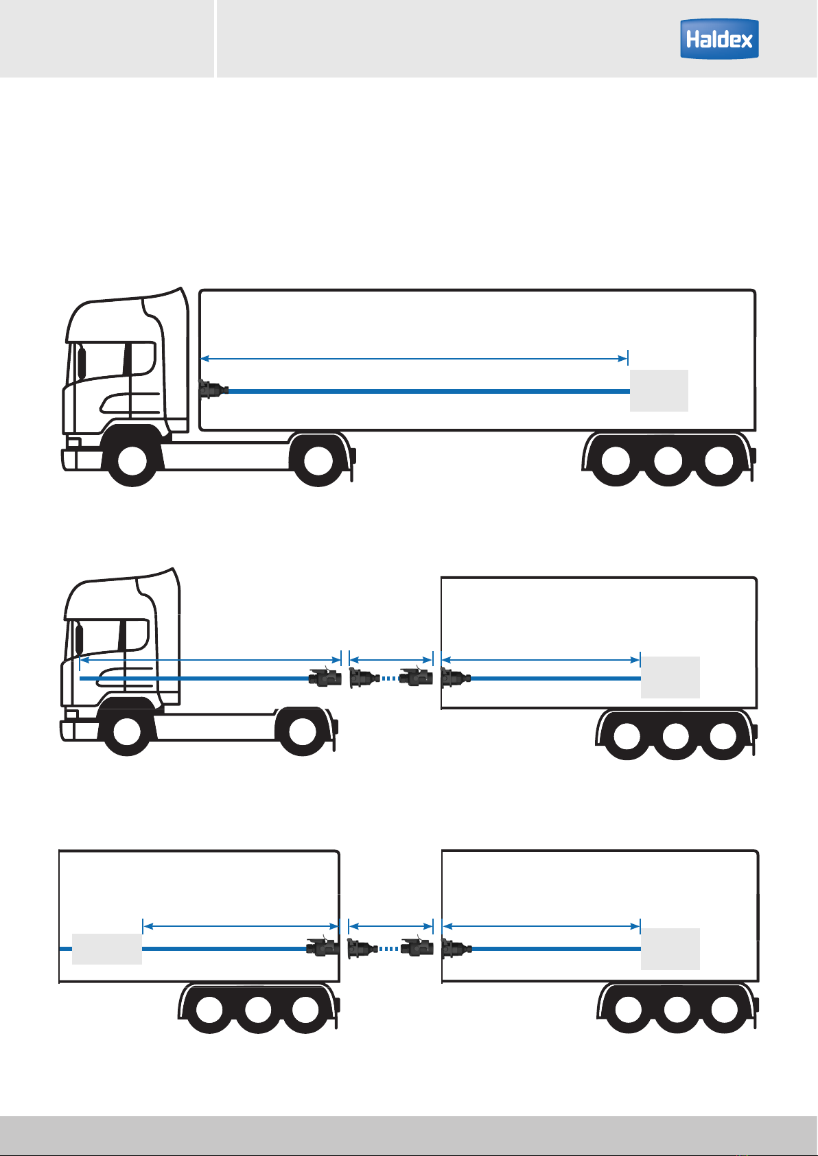
The product is intended to solve three installation problems: -
1. Extend the distance over which EBS can be fitted to certain very long trailers.
2. To connect two EBS together on one trailer, e.g. where there are more than five axles.
3. To provide an ISO 7638 output for a successor trailer in a road train.
Ideally any connector on the EB+ CAN Hub can have any function, with the EB+ CAN Hub self-configuring
according to the messages received. Where two ECU's are attached to the same trailer a configuration step may
be necessary at end-of-line to ensure correct addressing, as defined in ISO 11992-2.
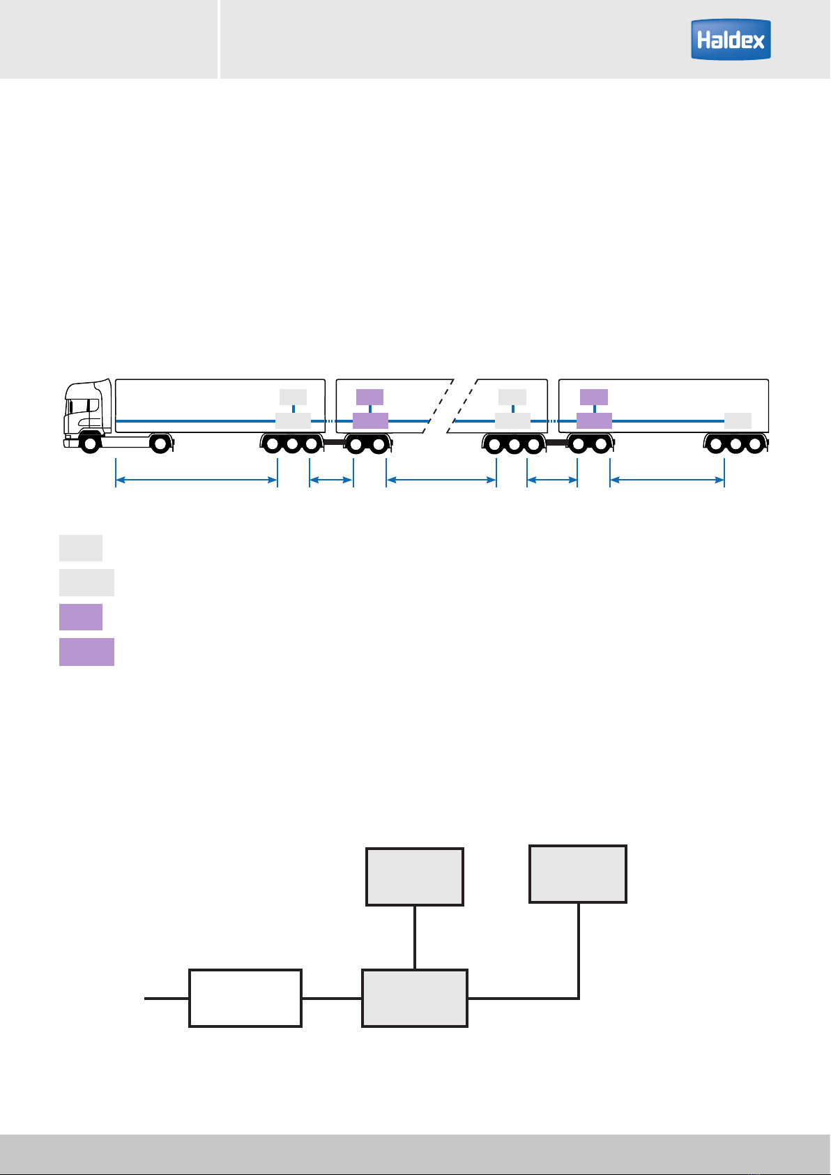
A road train consists of one truck (commercial vehicle) and one or more trailer(s) (towed vehicles). Dollies within
the road train shall be treated as additional towed vehicles.
1 2 3 4
Key
1 Truck (commercial vehicle)
2 Semi-Trailer (towed vehicle)
3 Converter dolly (towed vehicle)
4 Semi-Trailer (towed vehicle)
Introduction

EB+ CAN Hub
Installation
Guide
5
2020 Innovative Vehicle Solutions
EBS
18 m maximum ISO 7638 cable length (ISO 11992 pin 6 & 7)
Suzie
7 m
Towing
15 m
Towed
18 m
CAN Hub EBS
Suzie
7 m
Towing
15 m
Towed
18 m
EBS
The ISO 11992 CAN Bus is limited to 40 meters, where 22 meters is allocated for the truck (towing vehicle + Suzie
connection) and a maximum of 18 meters for the trailer (towed vehicle).
The maximum length to an ISO 7638 connector installed at the rear of the trailer is 15 m.

EB+ CAN Hub Installation
Guide
6Innovative Vehicle Solutions 2020
EB+ CAN Hub versions
The EB+ CAN Hub can operate in two modes:
1. Repeater, to pass through transmitted data when installed on an extendable trailer, or
2. Router, which routes messages between the ECU's on:
a) A towed trailer with two EBS ECU's installed, or
b) A trailer with just one installed EBS ECU
Connections to the EB+ CAN Hub and ECU (s) are made by EB+ Power A ISO 7638 cables connected to three
7–pin Haldex EB+ Power connectors located on the EB+ CAN Hub.
The EB+ CAN Hub automatically recognises a predecessor (Power), a local (Local) and a successor (Towing) ECU.

EB+ CAN Hub
Installation
Guide
7
2020 Innovative Vehicle Solutions
Repeater
EB+ CAN Hub is used as a repeater when the length of a cable allocated to the towed vehicle exceeds 18 meters.
With EB+ CAN Hub connected there is down-stream support for up to 40 meters of ISO 11992 cable.
EB+ CAN Hub automatically switches to repeater mode if only one EBS unit has been connected. CAN messages
are passed through irrespective of the CAN ID.
Reference the customer drawing 815 057 000 2 on page 44 for a wiring diagram example.
EB+ CAN Hub usage on an overlength trailer example
EBS
Up to 18 m
EBS
Up to 18 m Maximum 40 m
CAN Hub

EB+ CAN Hub Installation
Guide
8Innovative Vehicle Solutions 2020
Router
Transmission of the signals between the ECU's of the preceding and succeeding vehicles within the road train is
implemented by the router. It is done on a:
›Towed trailer with two EBS units installed (must be the last trailer in the train), or
›Where communication between ECU's installed on each of the vehicles needs to be provided
Reference the customer drawing 815 057 000 2 on page 45 for a wiring diagram example.
Towed trailer with two local EBS units
Both EBS units are connected to the same EB+ CAN Hub and both have the same trailer VIN number. This can be
implemented only on the last trailer on the road train.
EB+ CAN Hub as a router on one trailer (two local ECUs)
EBS 1 EBS 2
Up to 18 m
CAN Hub
EB+ CAN Hub
Predecessor
(e.g. Truck, Trailer , another
CAN Hub)
Local ECU Local ECU

EB+ CAN Hub
Installation
Guide
9
2020 Innovative Vehicle Solutions
Road Train
The EB+ CAN Hub on one trailer connects to:
1. The predecessor vehicle
2. The EBS ECU installed on it's own vehicle (local)
3. The successor vehicle (if any and can be another EB+ CAN Hub or EBS)
Road Train example:
EB+ CAN Hub as a router (with successor ECU i.e. another EB+ CAN Hub or EBS ECU on next trailer)
EBS fitted on a trailer
CAN Hub fitted on a trailer
EBS fitted on a Dolly / Centre axle trailer
CAN Hub fitted on a Dolly / Centre axle trailer
EBS
EBS
CAN Hub
CAN Hub
EB+ CAN Hub
Predecessor
(e.g. Truck, Trailer , another
CAN Hub)
Local ECU Successor
ECU
CAN Hub works as a router
installed on the first trailer
CAN Hub works as a router
installed on the penultimate trailer
EBS EBS EBSEBS
EBS
CAN Hub
up to 18 m up to 40 m up to 40 mup to 40 m up to 40 m
CAN HubCAN Hub CAN Hub

EB+ CAN Hub Installation
Guide
10 Innovative Vehicle Solutions 2020
External pressure sensor
EB+ CAN Hub supports communication between a towing vehicle not equipped with an EBS system (i.e. Truck
with ABS only system) and towed vehicles equipped with EBS system. This is done through the connection of an
external brake Pressure Sensor to the EB+ CAN Hub AUX port on the first trailer. The sensor provides information
about the pneumatic brake demand requested by a driver and EB+ CAN Hub converts it into an electric brake
demand signal and sends it to the trailers by generating the EBS11 (service brake demand) and EBS12 (pneumatic
control line and 1 x electrical control line) messages.
Required parts
Pressure Sensor 815 022 001
Pressure Sensor
connection
EB+ Pressure Sensor cable Length
814 001 502 10 m
814 001 522 0.75 m
814 001 532 3 m
814 001 542 5 m
814 001 572 18 m

EB+ CAN Hub
Installation
Guide
11
2020 Innovative Vehicle Solutions
With a tool having a flat end of Ø 3-2 mm insert and press in locking
tab of plug
While depressed pull out plug from housing.
Removal of blanking plug
The locking tab must be depressed before removing
the green Pressure Sensor AUX blanking plug.
Locking tab

EB+ CAN Hub Installation
Guide
12 Innovative Vehicle Solutions 2020
Pressure Sensor cable insertion
Ensure contact pins and seal are kept clean and free of any contamination prior to installation. Insert fully home in
the ECU’s housing.
Ensure that the connector location tab clicks into placePush connector into the ECU housing
Pressure Sensor cable inserted

EB+ CAN Hub
Installation
Guide
13
2020 Innovative Vehicle Solutions
Warning lamp
The warning lamp is used to indicate when a fault has occurred. It can be triggered either by the EB+ CAN Hub
ECU (working as a router or a repeater), or a local or a successor ECU (i.e. another EB+ CAN Hub in the road train,
EBS ECU such as EB+ Gen3). The warning lamp signal goes through pin 5 on EB+ Power A connector.
1
2
3
4
5
6** CAN - High
7** CAN - Low
Truck
EBS
Amber
(*Red)
Red
Fuse
25/30 A
16 A (*2A)
* ISO7638 - 1996
**Not fitted on ISO7638 - 1985
Lamp indicator
The warning device function depends on the ISO 7638
power supply used:
A warning lamp device located on the driver’s console
of the towing vehicle is operated from the ISO 7638
power cable only when the EB+ Gen3 is powered by
the ignition switch.
If a dedicated power source is unavailable to the
EB+ Gen3 from the ISO 7638 connector then system
integrity will not be indicated by the cab mounted
warning device.
As an option to the cab warning device a trailer
mounted warning lamp may be provided as an auxiliary
function. This lamp mimics the signal to the cab
warning device but will only function if the
ISO 7638 power is connected.
The signal produced by the trailer warning lamp may
be different to that produced by the cab device due to
possible modification of the cab device by the towing
vehicle.
A trailer-mounted warning lamp is not allowed in some
countries

EB+ CAN Hub Installation
Guide
14 Innovative Vehicle Solutions 2020
ON
OFF
2 sec.
ON
OFF
2 sec. 2 sec. @ 10 km/h
ON
OFF
2 sec.
ON
OFF
2 sec. 2 sec. @ 10 km/h
Option A
On for 2 seconds Warning device OK and system
self-checking
Off System self-checked (not sensors)
Option B
On for 2 seconds Warning device OK and system
self-checking
Off for 2 seconds System self-checked and preparing to
check sensors
On until moving
System waiting for vehicle to move
above 10 km/h in order to check that
sensors are working
Off
Once the vehicle is moving above
10 km/h and the warning device clears,
the electronic system is fully checked
System check procedure
1. On power up of the system, the warning device
must indicate one of the following sequences in order
to show a fault free system:
Option ‘A’
Option ‘B’
2. During the self-check procedure, the system cycles
the EPRV’s. With foot brake applied one exhaust of air
from each EPRV will be audible.
Once these two checks are made with correct results,
no further checks are required.
If the results are not satisfactory, Haldex DIAG+
software or EB+ Info Centre should be used to establish
the diagnosis.

EB+ CAN Hub
Installation
Guide
15
2020 Innovative Vehicle Solutions
Dimension and identication
Ref no. Description Notes
1Power A connection Connection for Power in or Power out
(any connection can be used for any function)
2Auxiliary connection Pressure Sensor connection
3 ECU grounding strip Should be connected to trailer chassis
215 mm
107.5 mm
85 mm
121.25 mm
1 1 1
2
3

EB+ CAN Hub Installation
Guide
16 Innovative Vehicle Solutions 2020
Chassis installation
The EB+ CAN Hub ECU will be fitted directly to the trailer chassis using the three holes with compression limiters.
The mounting fixing must provide an electrical connection between EB+ CAN Hub ECU and vehicle chassis.
Ground level
Deck of trailer
Position the EB+ CAN Hub assembly as high as possible
in the chassis to provide as much protection to the
assembly from direct spray, other road debris.
Pitch angle: assembly must be mounted vertically.
The mounting bracket flatness is to be not more than
0.5 mm deviation from its true plane i.e. the surface
must lie between two parallel planes 0.5 mm apart.
Check the earth continuity between EB+ CAN Hub ECU
and the vehicle chassis.
Resistance (R) to be less than 5 ohms
0 < R < 5 ohms
Secure the EB+ CAN Hub using bolts, flat washers and
noncorrosive self locking nuts.
Recommended fixing screw thread size M6 x 1.0
30 mm long (3 off) with 20.5 dia minimum washers,
locking torque 5.5 / 6.0 Nm.
The EB+ CAN Hub mounting parts (i.e. bolts, washers
and locking nuts etc) are to be protected from
corrosion to give 200 hours salt spray resistance.
Fixing
0 - 5Ω

EB+ CAN Hub
Installation
Guide
17
2020 Innovative Vehicle Solutions
Additional bracket design to be as rigid as possible.
The mounting fixing must provide an electrical
connection between EB+ CAN Hub ECU and vehicle
chassis.
The mounting bracket flatness is to be not more than
0.5 mm deviation from its true plane i.e. the surface
must lie between two parallel planes 0.5 mm apart.
Care should be taken to provide reasonable access to
the ECU to replace cables.
150 mm minimum
0.5 mm
4.0 mm min.
Mounting bracket
Fixing holes

EB+ CAN Hub Installation
Guide
18 Innovative Vehicle Solutions 2020
ISO 7638 connectors
Ensure contact pins and seal are kept clean and free of
any contamination prior to installation.
Unlock the ISO 7638 slide lock housing by pulling
down the blue latch.
Lock the ISO 7638 slide lock housing by pushing up the
blue latch.
Note:
Blanking plug (027514709) and o-ring (024505009)
must be fitted to the ISO 7638 connector if no cable
is inserted (i.e. EB+ CAN Hub using only two ISO 7638
connectors).

EB+ CAN Hub
Installation
Guide
19
2020 Innovative Vehicle Solutions
Connections
Make sure that all connections (socket and plug) are
clean and dry before assembly.
If required remove the blanking plug (027514709) from
the ISO 7638 position.
Trailer chassis
Feed all connectors through the chassis with protective
cap in place to avoid connector sockets being
contaminated. ø20.0
min
1
2
3
Remove protective cap from end of connector before
connecting into the ECU.

EB+ CAN Hub Installation
Guide
20 Innovative Vehicle Solutions 2020
Before inserting the ISO 7638 blue coloured 7-pin cable
connector, ensure contact pins and seal are clean and
free of any contamination prior to the installation.
Position ISO 7638 cable on the slide lock housing,
insert connector fully home.
Make sure that the connector is fully inserted into the
ECU slide lock housing.
Push in the blue lock slider.
Do not use extreme force to push in slider.
Warning:
›If difficulty is encountered in locking the slider, check
plug or connector for correct fitment
›If the white o-ring is visible, the plug is not installed
correctly and slider will not lock into position
This manual suits for next models
1
Table of contents
Other Haldex Diagnostic Equipment manuals