Kaixin DCU10 User manual

KAIXIN
DCU10
Full Digital Color Doppler Ultrasonic
Diagnostic Instruments (Vet)
User’s Manual
XUZHOU KAIXIN Electronic Instrument Co., Ltd.

Full Digital Color Doppler Ultrasonic Diagnostic Instruments (Vet) User’s Manual V1.01
Introduction
Thank you for purchasing DCU10 Full Digital Color Doppler Ultrasonic Diagnostic Instruments
(Vet).
Users shall carefully read through this manual and fully understand the text before operating the
equipment.
Please keep this manual after reading so that you can access at anytime when needed.
The user’s manual issue date: January 30, 2022, Version: V1.01
For the changes of appearance, this manual is subject to change without further notice!
Intellectual Property Information
The user’s manual and the corresponding intellectual property rights belonging to Xuzhou Kaixin
Electronic Instrument Company Ltd. (hereinafter referred to as Kaixin).
Individual or organization may not copy, modify or translate any part of this user’s manual, without
the express written permission of Kaixin.
Statement
Kaixin has the final explanation right of this user’s manual.
Kaixin was considered responsible for the safety, reliability and performance in case of meeting all
the following requirements:
1. Assembly, expansion, readjustment, improve and repair are all performed by professionals
recognized by Kaixin;
2. All replacement parts and accessories, consumables involved repairs are Kaixin company
(original) or approved byKaixin;
3. Related electrical equipment complies with national standards and the requirements of the user’s
manual;
4. Operate the product in accordance with the user’s manual.
Warranty and repairservice
Purchased the product warranty, sees the company's service policies.
The qualified service personnel who get Kaixin written authorization can repairthe instrument out of
warrantybythemselves. But this should be agreed by Xuzhou Kaixin Electronic Instrument Co., Ltd. We
will provide circuit diagrams, component part lists or other information to assist service personnel to repair
those parts of our equipment that are designated byour company as repairable by service personnel.
Manufacturer’s Information
Xuzhou Kaixin ElectronicInstrument Co., Ltd.
Kaixin Mansion, C-01, Economic Development Zone, Xuzhou, Jiangsu, China.
Post Code: 221004
Tel: +86-516-87732932 87733758
Fax: +86-516-87732932 87792848
Website: http://www.kxele.com
E-mail: info@kxele.com
F-1

Full Digital Color Doppler Ultrasonic Diagnostic Instruments (Vet) User’s Manual V1.01
Important Statement
1. User shall be fully responsible for the maintenance and management of this product after
purchasing this product.
2. Even in the warrantyperiod, warranty does not include the following:
a) Damage or loss caused by error or rough using.
b) Damage or loss caused byforce majeure (such as fires, earthquakes, floods, or lightning etc.).
c) Damage or loss caused by not meeting the conditions of use specified by the system, such as
inadequate power supply, incorrect installation or environmental conditions do not meeting
the requirements.
d) Damage or loss caused by not used the system in theinitial buyregion.
e) Damage or loss caused by the system purchased not by Kaixin or its authorized dealer or
agents.
3. Medical personnel qualified with professional qualifications only to use this system.
4. Do not modify the software or hardware of the equipment without authorization of the
manufacturer.
5. In any case, Kaixin shall not be liable for the problems, damages or losses due to re-installation,
alteration or repair the system by non-Kaixin designated personnel.
6. This product isintendedto provide clinical diagnostic data for the doctor.
The doctor shall be responsible for the diagnostic process. Kaixin shall not be liable for any
problems arising out of the process.
7. Be sure to back up important data to external storage media, such as notebooks.
8. Due to operator’s error or abnormal condition causing the data stored in the internal system is lost,
Kaixin is not responsible.
9. This user’s manual contains warnings for predictable dangers. Users shall also exercise care at any
time to be aware of the dangers unforeseen in this manual. Kaixin shall not be liable for the
damages and losses arising out of neglecting to follow the operation instructions herein described.
10. This user’s manual shall be furnished with the machine so that managerial and operating
personnel can refer to it any time as necessary. Once the managerial personnel of the system
changes, it shall hand over this user’s manual.
11. The use of inappropriate accessory will reduce the performance of the product.
12. The use of the accessory, transducer or cable other than those specified may result in increased
emissions or decreased immunityof the system.
13. The system should not be used adjacent to or stacked with other equipment and that if adjacent or
stacked use is necessary, the system should be observed to verify normal operation in the
configuration in which it will be used.
14. The system needs to be specifically for EMC protection and need to be installed and maintenance
in the environment meeting the following provided EMC information.
15. The system may be interfered with by other equipment, even if that other equipment complies
with CISPR emission requirements.
16. Prevent electromagnetic interference (Conducted Immunity). Due to technical limitations,
conducted immunity level is limited to 1 Vrms, conducted immunity level higher than 1 Vrms
may cause the image display of the system interference and affecting the diagnosis and
measurement. We recommend the system awayfrom the conduction noise source.
17. Deal with the exhausted product according to the local statute.
18. The maintenance and servicing of product shall be performed by the trained engineer or by Kaixin
Electronic Instrument Company Ltd.
F-2

Full Digital Color Doppler Ultrasonic Diagnostic Instruments (Vet) User’s Manual V1.01
Safety Cautions
1. Warning Symbols and Definitions
The following warning symbols are used in this manual to indicate safety level and other important items.
Please remember these symbols and understand the meaning as you read this user’s manual. These
symbols convey specific meanings as detailed in the table below:
Symbols &Words
Connotation
Danger
Indicates an imminent danger that may result in personal death or
serious injuryif not avoided.
Warning
Indicates a potential danger that may result in personal injury if not
avoided.
Attention
Indicates a potential danger or unexpected use condition that may
result in light injury or property loss or affectingthe use if not avoided.
[ ]
Indicates on-screen objects such as menu items and prompt.
Boldfaced Word
Indicates keys on the control panel.
2. Safety Symbols
Symbols
Meaning
Symbols
Meaning
Type BF applied part
Up
Power on/Standby key
Keep dry
AC (alternating current)
Fragile
Equipotential terminal
Stacking limit by number
Follow instructions for use
Temperature limits (Storage and
transport)
Marking for the separate collection of
electrical and electronic equipment
Humidity limitation (Storage
and transport)
Atmospheric pressure limitation
(Storage and transport)
F-3

Full Digital Color Doppler Ultrasonic Diagnostic Instruments (Vet) User’s Manual V1.01
3. Labels
Label
Description
Danger:
1. It may have explosion hazard if used with
flammable gas.
2. Operate the probe with care. Read the
probe information in the relevant manual
for proper probe use.
Attention:
It is prohibited to scratch or squeeze the
LCD/LED.
Attention:
Do not place object on the machine. Do not
apply external force on the machine. Close
the keyboard before moving the machine.
Symbol for the marking of electrical and electronics devices according to
Directive 2012/19/EU. The device, accessories and the packaging have to be
disposed of waste correctly at the end of the usage. Please follow Local
Ordinances orRegulations for disposal.
F-4

Full Digital Color Doppler Ultrasonic Diagnostic Instruments (Vet) User’s Manual V1.01
Contents
Chapter1 TechnicalSpecifications...................................................................................................................................................-1-
1.1 Technical Parameters..................................................................................................................................................... - 1 -
1.2 Functions........................................................................................................................................................................ - 1 -
Chapter2 SystemOutline..................................................................................................................................................................-3 -
2.1 Structurecomposition of the instrument....................................................................................................................... - 3 -
2.2 Main Unit Overviews.................................................................................................................................................... - 3 -
2.2.1 LeftView.....................................................................................................................................................................- 3 -
2.2.2 RearView.................................................................................................................................................................... - 4 -
2.3 Peripherals Ports View................................................................................................................................................... - 4 -
2.4 Power Supply Port......................................................................................................................................................... - 5 -
2.5 Control Panel..................................................................................................................................................................- 5 -
2.6 Main Screen................................................................................................................................................................... - 8 -
2.7 Regular ExaminationWorkflow ...................................................................................................................................- 9 -
Chapter3 SystemConfiguration....................................................................................................................................................-10-
3.1 Typical configuration...................................................................................................................................................- 10 -
3.2 Optional parts...............................................................................................................................................................- 10 -
Chapter4 OperationCondition......................................................................................................................................................-11-
4.1 Power supply................................................................................................................................................................ - 11 -
4.2 Operation Environment............................................................................................................................................... - 11 -
4.3 Storage andTransport.................................................................................................................................................. - 11 -
Chapter5 SystemInstallationandCheck....................................................................................................................................-12-
5.1 System installation.......................................................................................................................................................- 13 -
5.2 Ultrasonic probe installation........................................................................................................................................- 13 -
5.2.1 Connecting the probe................................................................................................................................................- 14 -
5.2.2 Disconnecting the probe...........................................................................................................................................- 14 -
5.3 Connect to equipotential wire......................................................................................................................................- 14 -
5.4 Connect to power.........................................................................................................................................................- 15 -
5.5Assembling and Disassembling the battery................................................................................................................- 15 -
5.5.1 Disassembling the battery.........................................................................................................................................- 15 -
5.5.2Assembling the battery.............................................................................................................................................- 15 -
5.6 Connecting the Peripherals..........................................................................................................................................- 15 -
5.6.1 Connecting the foot switch.......................................................................................................................................- 15 -
5.6.2 Connecting the video printer....................................................................................................................................- 15 -
5.6.3 Connecting the graphic printer.................................................................................................................................- 16 -
5.7 Booting/Standby/Powering off....................................................................................................................................- 16 -
5.8 Ultrasonic probe check before and after operation.....................................................................................................- 17 -
5.9 Main unit check before and after operation................................................................................................................- 17 -
5.9.1 Inspection before start-up.........................................................................................................................................- 17 -
5.9.2 Inspection after start-up............................................................................................................................................- 17 -
Chapter6 PresettingSystem............................................................................................................................................................-18-
6.1 Presetting the System...................................................................................................................................................- 18 -
6.2 Presetting the Probe/Exam..........................................................................................................................................- 20 -
6.3 Presetting the Image Menus........................................................................................................................................- 21 -
6.4 Presetting the Measurements.......................................................................................................................................- 21 -
6.5 Presetting theAnnotations...........................................................................................................................................- 22 -

Full Digital Color Doppler Ultrasonic Diagnostic Instruments (Vet) User’s Manual V1.01
6.6 Presetting DICOM.......................................................................................................................................................- 23 -
6.7 Presetting the Report Template ...................................................................................................................................- 25 -
6.8 Presetting the Data.......................................................................................................................................................- 25 -
6.9 System Information .....................................................................................................................................................- 25 -
Chapter7 PatientInformation........................................................................................................................................................-26-
7.1 Registering a Patient....................................................................................................................................................- 26 -
7.2 Selecting the Probe and ExamType ...........................................................................................................................- 26 -
7.3 Ending the Exam..........................................................................................................................................................- 27 -
Chapter8 OptimizingtheImage....................................................................................................................................................-28-
8.1 B Mode.........................................................................................................................................................................- 28 -
8.1.1 Entering the B Mode.................................................................................................................................................- 28 -
8.1.2 Optimizing the B Mode Image.................................................................................................................................- 28 -
8.2 Color Doppler Flow Imaging (Color) Mode..............................................................................................................- 32 -
8.2.1 Entering the Color Mode..........................................................................................................................................- 32 -
8.2.2 Optimizing the Color Mode Image..........................................................................................................................- 33 -
8.3 PDI Mode.....................................................................................................................................................................- 36 -
8.3.1 Entering the PDI Mode.............................................................................................................................................- 36 -
8.3.2 Optimizing the PDI Mode Image.............................................................................................................................- 36 -
8.4 M Mode........................................................................................................................................................................- 37 -
8.4.1 Entering the M Mode................................................................................................................................................- 37 -
8.4.2 Optimzing the MMode Image.................................................................................................................................- 37 -
8.5 PW Mode.....................................................................................................................................................................- 40 -
8.5.1 Entering the PW Mode.............................................................................................................................................- 40 -
8.5.2 Optimizing the PW Mode Image.............................................................................................................................- 41 -
Chapter9 ProcessingtheImages....................................................................................................................................................-44-
9.1 Displaying the image...................................................................................................................................................- 44 -
9.1.1 Dual-splitting Display...............................................................................................................................................- 44 -
9.1.2 Quad-splitting Display..............................................................................................................................................- 44 -
9.2 Magnifying the Image .................................................................................................................................................- 45 -
9.3 Freezing the Image.......................................................................................................................................................- 45 -
9.4 Viewing and Cropping the Cine..................................................................................................................................- 45 -
9.4.1 Reviewing the Cine...................................................................................................................................................- 46 -
9.4.2 Cropping the Cine.....................................................................................................................................................- 46 -
9.5Annotating the Image...................................................................................................................................................- 46 -
9.5.1 TextAnnotation.........................................................................................................................................................- 46 -
9.5.2ArrowAnnotation.....................................................................................................................................................- 46 -
9.5.3 BodymarkAnnotation..............................................................................................................................................- 46 -
9.5.4 Deleting theAnnotation............................................................................................................................................- 47 -
Chapter10 MeasurementsandCalculations...............................................................................................................................-48-
10.1 Measurement Screen and Keys.................................................................................................................................- 48 -
10.2 Measurement Menu...................................................................................................................................................- 49 -
10.3 Measurement Preset...................................................................................................................................................- 49 -
10.4 Measurement Error....................................................................................................................................................- 49 -
10.5 General Measurement................................................................................................................................................- 50 -
10.5.1 B Mode Measurements ..........................................................................................................................................- 50 -
10.5.2 M Mode Measurements .........................................................................................................................................- 53 -

Full Digital Color Doppler Ultrasonic Diagnostic Instruments (Vet) User’s Manual V1.01
10.5.3 Color/PDI Mode Measurements............................................................................................................................- 54 -
10.5.4 PW Mode Measurements.......................................................................................................................................- 55 -
10.6 Specific Measurements and Calculations.................................................................................................................- 57 -
10.6.1Abdomen Measurements........................................................................................................................................- 57 -
10.6.2 Obstetrics Measurements.......................................................................................................................................- 58 -
10.6.3 Cardiology Measurements .....................................................................................................................................- 59 -
10.6.4Vascular Measurements..........................................................................................................................................- 67 -
10.6.5 Small Parts Measurements.....................................................................................................................................- 68 -
Chapter11 Report..............................................................................................................................................................................-69-
11.1 Reviewing the Report................................................................................................................................................ - 69 -
11.2 Editing the Report......................................................................................................................................................- 69 -
11.2.1 Entering Ultrasound Comments.............................................................................................................................- 69 -
11.2.2Adding Ultrasound Images.....................................................................................................................................- 69 -
11.3 Saving the Report.......................................................................................................................................................- 69 -
11.4 Printing the Report.....................................................................................................................................................- 69 -
Chapter12 ManagingImages/Data...............................................................................................................................................-70-
12.1 Saving the Image/Cine ..............................................................................................................................................- 70 -
12.2 Reviewing the Image/Cine........................................................................................................................................- 70 -
12.3 Deleting the Image/Cine............................................................................................................................................ - 71 -
12.4 Printing the Image......................................................................................................................................................- 71 -
12.5 Saving Data................................................................................................................................................................- 71 -
12.5.1 Saving to USB Storage Devices.............................................................................................................................- 72 -
12.5.2 Saving to DICOM Server.......................................................................................................................................- 72 -
Chapter13 Punctureguide..............................................................................................................................................................-73-
13. 1 Operation of puncture guide line..............................................................................................................................- 73 -
Chapter14 SystemMaintenance....................................................................................................................................................-74-
14.1 Maintenance byusers ................................................................................................................................................- 74 -
14.1.1 System cleaning and disinfection...........................................................................................................................- 74 -
14.1.2Clean the probe cable and its connector................................................................................................................- 76 -
14.1.3 Clean the LED screen.............................................................................................................................................- 76 -
14.1.4 Clean the control panel, shell and probe bracket...................................................................................................- 76 -
14.2 Replace the fuse.........................................................................................................................................................- 76 -
14.3 Replacement of power supplycord ..........................................................................................................................- 76 -
14.4 Using the Battery.......................................................................................................................................................- 76 -
14.4.1 Precautions..............................................................................................................................................................- 76 -
14.4.2 Charging the Battery...............................................................................................................................................- 77 -
14.5 Data maintenance.......................................................................................................................................................- 78 -
14.6Troubleshooting.........................................................................................................................................................- 78 -
14.7 Maintenance byservice personnel............................................................................................................................- 79 -
Chapter15 StorageandTransportation.......................................................................................................................................-80 -
Chapter16 SafetyClassification.....................................................................................................................................................-80-

Full Digital Color Doppler Ultrasonic Diagnostic Instruments (Vet) User’s Manual V1.01
- 1 -
Chapter 1 Technical Specifications
1.1 Technical Parameters
1. Monitor: 15'' LED screen
2. Power supply: 100-240V~ 50/60Hz 1.2-0.6A
3. Dimension: 400mm (L) x 394mm (H) x 172 (D)
4. Weight: approximately 8.1 kg
1.2 Functions
1. System preset: hospital name, language, date and time format, image and film type, TI,
video mode, printer, brightness and color temperature, system date and time, system wait,
reset configure, key sound, backlight, UI style;
2. Probe and exam mode preset;
3. Image menu preset;
4. Measure preset;
5. Comment preset;
6. DICOM preset;
7. Report template;
8. Preset data;
9. System information display;
10. Patient information input function;
11. Selecting the probe and exam type function;
12. Ending the exam;
13. B, B/M, M, Color, PDI, PWmode conversion function;
14. B mode image adjustment functions: gain, TGC, focus position/number, frequency,
depth, gray map, colorize, dynamic range, scan scope, scan density, speckle reduction,
frame correlation, line average, space compound, edge enhance, image enhance, acoustic
power, vertical reverse, horizontal reverse, bodytype;
15. Color image adjustment functions: gain, frequency, scale, sensitivity, baseline, flow
speed, wall filter, color reverse, frame correlation, scan density, steer, color map, post
process, acoustic power, dual live;
16. PDI image adjustment functions: gain, frequency, scale, sensitivity, flow speed, wall
filter, frame correlation, scan density, steer, color map, post process, acoustic power, dual
live;
17. M mode image adjustment functions: gain, depth, sweep speed, focus position, dynamic
range, gray map, colorize, speckle reduction, line average, edge enhance, full screen,
vertical reverse, acoustic power;
18. PW image adjustment functions: gain, frequency, scale, baseline, SV, angle, sweep speed,
scale unit, reverse, steer, colorize, wall filter, dynamic range, full screen, acoustic power,
smooth;
19. Displaying the image (dual-splitting, quad-splitting display);
20. Magnifying the image;
21. Image freeze/unfreeze function;
22. Viewing and cropping the cine;
23. Text/arrow annotation, body marks function and delete the annotation;
24. B mode conventional measurement function: distance, area and circumference, volume,
Full Digital Color Doppler Ultrasonic Diagnostic Instruments (Vet) User’s Manual V1.01
- 2 -
area ratio, distance ratio, angle;
25. M mode conventional measurement function: distance, time, heart rate, slope rate;
26. Color/PDI mode conventional measurement function: distance, area and circumference,
volume, area ratio, distance ratio, angle;
27. PWmode conventional measurement function: flow speed ratio, velocity, time, heart rate,
acceleration, spectrum trace;
28. Abdomen application measurement function: liver, gallbladder, pancreas, spleen, kidney;
29. Obstetric application measurement and GA/EDD calcualtion function;
30. Cardiac application measurement function: left ventricle, inner diameter of right
ventricle end diastole,inner diameter of main pulmonary artery, mitral valve, aorta,
ejection time, left ventricle mass weight;
31. Vascular application measurement function: CCA, ICA, ECA, VA, upper ext vein, lower
ext vein;
32. Small parts thyroid and isthmus application measurement function;
33. Automatically generate report, view the report, add the diagnostic information, print the
report;
34. Managing images function: save, review, delete, print;
35. Data storage and sending function;
36. Puncture guide function.

Full Digital Color Doppler Ultrasonic Diagnostic Instruments (Vet) User’s Manual V1.01
- 3 -
Chapter 2 System Outline
You should familiar with the structure composition, operation of the keys and buttons, the general
work flow before using this instrument.
2.1 Structure composition of the instrument
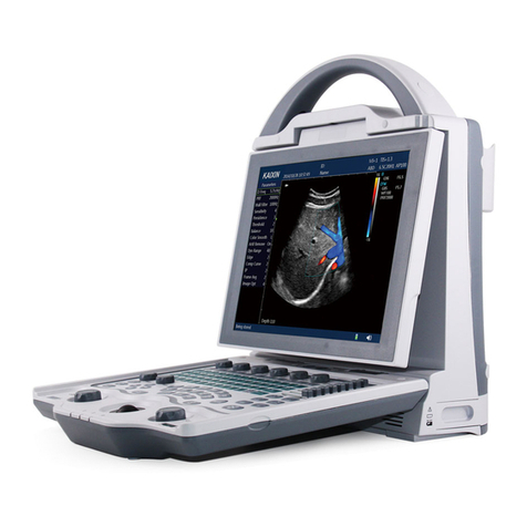
DCU10 full digital color Doppler ultrasonic diagnostic instruments (Vet) are composed of main unit
and probe, etc.
2.2 Main Unit Overviews
Figure 2-1 Main Unit Overview
2.2.1 Left View
Figure 2-2 Left View

Full Digital Color Doppler Ultrasonic Diagnostic Instruments (Vet) User’s Manual V1.01
- 4 -
2.2.2 Rear View
Figure 2-3 RearView
2.3 Peripherals Ports View
Figure 2-4 Peripherals Ports
No.
Name
Function
1
VGAport
Used for connecting the video equipment generating VGA
signals, such as monitor and projector.
2
Serial port
Used for connecting the debugging cable and exporting the
debugging information for after-sales servicing.
3
Footswitch port
Used for connecting the footswitch.
4
Video output
port
Used for connecting the video equipment generating the
composite video signals, such as video printer.
5
Network port
Used for connecting DICOM server or network.
6
USB port
Used for connecting the usb equipment,such as u disk and
usb printer.

Full Digital Color Doppler Ultrasonic Diagnostic Instruments (Vet) User’s Manual V1.01
- 5 -
2.4 Power Supply Port
Figure 2-5 Power Supply Port
No.
Name
Function
1
AC power input
port
Used for connecting theAC power supply.
2
Equipotential
Terminal
Used for balancing the protective earth potentials between
thisinstrument and other electrical equipment.
2.5 Control Panel
SN
Sign
Name
Functions
IndicatorsArea
1
Power indicator
The indicator lights on when the system is powered
bythe alternative current.
2
Battery capacity
indicator
The indicator lights on the when the system is
powered by the battery.
3
Battery charge
indicator
The indicator lights on when the battery is charged
and lights off when the batteryis fullycharged.
KeyboardArea
1
ESC Key
1. When dialog is open, press it to close the
opened dialog.
2. When preset submenu is displayed, press it to
exit preset submenu and return to previous
menu.
3. When preset primarymenu is displayed, press it
to exit preset primary menu.
2
Help Key
Press it to displayhelp information.
3
Report key
Press it to enter the report screen.
4
Station key
Press it ot enter the workstation screen.
5
Preset key
Press it to enter the system preset screen.
6
Save current image
parameters key
Press it to save the parameters setting of the current
imaging mode.
7
Restore the preset
image parameters key
Press it to restore the parameters setting of the
current imagingmode from preset.

Full Digital Color Doppler Ultrasonic Diagnostic Instruments (Vet) User’s Manual V1.01
- 6 -
8
Lito key
Press it to activate the litofunction.
9
Biopsykey
Press it to activate the biopsy function.
10
Menu key
Press it to hide/displaythe menu function.
11
Body mark key
Press it to enter/exit the body mark status.
12
Arrow annotation key
Press it to enter/exit the arrow annotation status.
13
Text annotation key
Press it to enter/exit the text annotation status.
14
Clear key
Press it to remove all the annotations and
measurements from the screen.
15
Left/right key
● Adjust the left and right positions of the curosr
under the text comment state.
●Press it to adjust the steer angle in Color/PDI
status.
●Press it to adjust the sampling line angle in PW
status.
16
Up/down key
Press it to adjust the volume of the frequency
spectrum in the real time PW mode.
17
Ctrl +
blank
Typewriting selection
key
In Chinese screen, press the combined keys to select
the desired typewriting.
18
-
Other keys
Achieve the functions similar with the keys on the
keyboard of the computer.
Function Keys
1
Power on/Standby
key
Press it to power on or off the instrument or to
enable standbymode.
2
TGC slide pot
There are 8 TGC slide pot. Move it to adjust the
gain of the specified depth.
3
Patient key
Press it to enter the patient information screen to
create or edit the patient information.
4
Probe and exam
mode selection key
Press it to enter the probe and exam selection mode
to select the probe and the application part.
5
Review key
Press it to enter the file review screen.
6
End the exam key
Press it to end the exam of the current patient.
7
Select
Select knob
Rotate this knob to select a menu item and press the
knob to adjust the menu parameters.

Full Digital Color Doppler Ultrasonic Diagnostic Instruments (Vet) User’s Manual V1.01
- 7 -
8
B mode key
Press it to enter the B mode.
9
Color mode key
Press it to enter/exit the color flow Doppler mode.
10
PDI mode key
Press it to enter the PDI mode.
11
PW mode key
Press it to enter/exit the pulsed wave Doppler mode.
12
M mode key
Press it to enter/exit the M mode.
13
Dual displaykey
Press it to enter the dual display.
14
Quad-display
key
● If it is not in four images view, press this key to
enter four images view.
● If it is in four images view, press this key to
switch real time display image.
15
Gain
Gain knob
Rotate it to adjust the gain of the current mode.
16
Cursor key
Press it to displayor hide the cursor.
17
Measurement key
Press it to activate or deactivate the measurement.
18
Change key
When measuring,
● Press it to switch between the ending point and
the starting point in the distance measurement.
● Press it to switch between the long axis and the
short axis in the ellipse measurement.
Non-measurement state, real-time scanning:
● In PW mode, it is used to switch the real-time/
freeze display status of 2D image and PW image.
19
General measurement
key
Press it to enter/exit the general measurement.
20
Confirmation key
Press it to confirm the current operation.
21
Angle
Angle knob
● Rotate it to adjust the direction mark of the probe
in the body mark annotation status.
● Rotate it to adjust the direction of the arrow in the
annotation status.

Full Digital Color Doppler Ultrasonic Diagnostic Instruments (Vet) User’s Manual V1.01
- 8 -
● Rotate it to adjust the calibrated angle in the PW
mode.
●Rotate it to delete or restore the last trace during
the trace measurement.
22
Depth key
Used for increasing or decreasing the depth of the
image.
23
Magnification key
Used for magnifying the interest area of the image.
24
Playback key
Press it to inactivate/activate the manual review of
the cine in the cine mode.
25
Save key
Press it to save the current image in the frozen
mode.
26
Freeze key
Press itto freeze/unfreeze the image.
27
,
User-defined shortcut
key
Press it to enablethe shortcut function defined by
the user. For details, refer to Section 6.1 System
Preset.
2.6 Main Screen

Full Digital Color Doppler Ultrasonic Diagnostic Instruments (Vet) User’s Manual V1.01
- 9 -
1. LOGO
2. Owner name
3. Hospital Name
4. Direction mark of the probe
5. Gender
6. Patient ID and patient's type
7. Probe model
8. MI and TIS indices
9. Exam type
10. Frozen image
11. Graymap and color map (Color/PDImode)
12. Date and time
13. Imaging parameters
14. Focus
15. Imaging area
16. Scale bar
17. Cine schedule bar
18. Menu
19. Thumbnail area
20. Prompt
21. Status
2.7 Regular Examination Workflow
The regular examination workflow is as shown in Figure 2-6. If you are not familiar with any of the
operations, please consult the relevant chapter.
Clear the history
measurement data
and start a new exam
Create a patient
Select the
saved patient
Select the probe
and exam type Select the
imaging mode
Review/annotate
the image
Perform
measurements
Save the image
Complete the scan
and save the patient
report
Send data to printer
/server/USB device
End the exam Perform a scan
Figure 2-6 Regular ExaminationWorkflow
For creating a patient, refer to Section 7.1 Registering a Patient.
For selecting the probe and exam type, refer to Section 7.2 Selecting the Probe and Exam
type.
For selecting the imaging mode, refer to Chapter 8 Optimizing the Image.
For reviewing/annotating the image, refer to Chapter 9 Processing the Images.
For performing measurements, refer to Chapter 10Measurements and Calculations.
For saving the image, refer to Section 12.1 Saving the Image/Cine.
For sending data to printer/server/USB storage device, refer to Section 12.4 Printing the
Image and Section 12.5 Saving Data.
For completing the scan and saving the patient report, refer to Chapter 11 Report.
For ending the exam and clearing the historymeasurement and starting a new exam, refer to
Section 7.3 Ending the Exam.

Full Digital Color Doppler Ultrasonic Diagnostic Instruments (Vet) User’s Manual V1.01
- 10 -
Chapter 3 System Configuration
3.1 Typical configuration
1. Main unit 1 unit
2. 6.5 MHz micro-convex probe 1 PC
3. 7.5 MHz high frequency linear array probe 1 PC
4. Built-in battery 1 PC
5. Power supply cable 1 PC
6. Equipotential wire 1 PC
7. Network cable 1 PC
3.2 Optional parts
1. 3.5MHz convex arrayprobe
2. 6.5MHz animal transrectal linear arrayprobe
3. Foot switch

Full Digital Color Doppler Ultrasonic Diagnostic Instruments (Vet) User’s Manual V1.01
- 11 -
Chapter 4 Operation Condition
4.1 Power supply
Power supply: 100-240V~ 50/60Hz,1.2-0.6A
4.2 Operation Environment
Ambient temperature: 10℃-40℃
Relative humidity: 30%-75% (without condensation)
Atmospheric pressure: 700hPa-1060hPa
Altitude: < 2000 m
Overvoltage: Overvoltage CategoryⅡ
Pollution degree: 2
4.3 Storage and Transport
Ambient temperature: -20℃-55℃
Relative humidity: 30%-93% (without condensation)
Atmospheric pressure: 700hPa-1060hPa
Attention:The main voltage is varies with different countries or regions.
Danger: Do not use this equipment where flammable gas (such as anesthetic gas, oxygen
or hydrogen) or flammable liquid (such as alcohol) are present. Failure to do so may
result in explosion.
Warning: Avoid using this equipment with high-frequency electric knife,
high-frequency therapy equipment or defibrillators and other electronicdevices, or may
an electric shock occur to the patient.
Attention: Using radio transmitting equipment nearby the system may interfere with
the normal operation of the system. Prohibited carry or use of devices that can generate
radio waves within the room installed this system, such as cell phones, radio transceivers
and wireless remote control toys.
Attention:Systemshould be avoided using in following environments:
1. Splash 2. Moist 3. Rain
4. Thunderstorm weather 5. No ventilation 6. Dust
7. Close to heat source 8. Direct sunlight 9. Dramatic temperature change
10. Chemical medicines 11.Poisonous gas 12. Corrosive gas
13. Strong shock 14. Strong electromagnetic field (e.g. MRI)
15. Radiation (e.g. X-ray, CT) 16. Defibrillators orshort wave therapy equipment

Full Digital Color Doppler Ultrasonic Diagnostic Instruments (Vet) User’s Manual V1.01
- 12 -
Chapter 5 System Installation and Check
You should complete the preparations before the exam, such as move, position and adjust the
instrument, connect the power supply, probe or other peripherals.
Warning:
1. All plugs of instruments of this equipment shall be connected into the power socket with
protectively earth on the wall and the socket must meet the requirement of power rating
of instrument. Use of multiple portable socket-outlets may affect protective earth to make
leakage currents exceed the safety requirements.
2. Equipotential wire shall be connected firstly before equipment is connected into the
socket. The plug of the equipment shall be pulled out of socket before pluck the
equipotential wire, or it may cause electric shock. Do not connect the grounding wire to
any gas pipe orwater pipe, orit may cause bad grounding and danger of explosion.
3. If the machine is connected to other equipment, each equipotential wire shall be connected
using equipotential wire. Failure to do so may cause electricshock.
4. This equipment is not waterproof, not use this equipment in place where liquid may into
the interior of the equipment. Never pour any liquid on the equipment; otherwise there
will be danger of electric shock or cause equipment damage. If accidentally spill liquid on
the equipment, turn off the powerimmediately and contact yourlocal representative.
5. Prohibit the live parts of the equipment orother devices (such as various signal input and
output ports, etc.) contact with the patient, if this equipment orother equipment has
failure, the patient will have danger of electric shock.
6. Additional equipment connected to the medical electrical equipment must comply with
the respective IEC orISO standards (e.g. IEC60950 for data processing equipment, IEC
60601-1 formedical equipment). Furthermore all configurations shall complywith the
requirements formedical electrical systems (seeIEC 60601-1-1).Anybody connecting
additional equipment to medical electrical equipment configures a medical systemand is
therefore responsible that the system complies with the requirements formedical
electrical systems.Attention is drawn to the fact that local laws take priority over the
above mentioned requirements. If in doubt, consult yourlocal representative or the
technical service department.
Warning:
1. When instrument worksabnormally, do stop working, turn off the power and check the
reason, then contacts the KAIXIN Company about it.
2. Turn off power and pull out of theplug from socket after each ultrasonic diagnostic
operation.
3. Itisforbidden to drag and press thepower and probe cables emphatically; regularly
inspect whether there ispull-apart and bareness,if there is the phenomena like this, turn
off power supply immediately, stop using it and change itfornew one.
4. It is forbidden to load and unload theprobe ormove the instrument in galvanic to avoid
danger of safety.
5. Pull out of the plug from socket after operation in thunderstorm weather to avoid the
instrument being damaged by lightening.
6. If the temperature changes greatly in short time will cause vaporrecovery inside of
instrument, the case may damage the instrument.
7. The equipment is switched completely only by disconnecting the power supply from the
wall socket.
Warning: To avoid the risk of electric shock, this equipment must only be connected to
a supply mains with protective earth.
Other manuals for DCU10
1
Table of contents
Other Kaixin Diagnostic Equipment manuals

Kaixin
Kaixin K10 User manual

Kaixin
Kaixin RKU10 User manual

Kaixin
Kaixin KX5600 User manual

Kaixin
Kaixin DCU12 User manual

Kaixin
Kaixin KX5600F User manual

Kaixin
Kaixin MSU2 User manual

Kaixin
Kaixin MSU1 User manual

Kaixin
Kaixin MSU1Plus User manual

Kaixin
Kaixin RKU10 User manual

Kaixin
Kaixin DCU10 User manual