manuals.online logo
Brands
  1. Home
  2. •
  3. Brands
  4. •
  5. LevelOne
  6. •
  7. Switch
  8. •
  9. LevelOne Infinity IES-1085 User manual

LevelOne Infinity IES-1085 User manual

4 x 802.3af + 4 x 802.3at + 2 GE SFP Managed Switch
Quick Installation Guide
Default Setting
IP
Login
Password
Console
IES-1085
4 x 802.3af + 4 x 802.3at + 2 GE SFP Managed Switch
DIN-rail
Quick Installation Guide
192.168.1.10
root
[blank]
115200, n, 8, 1
4 x 802.3af + 4 x 802.3at + 2 GE SFP Managed Switch
-40 to 75C,
Quick Installation Guide
v1.00 - 1206
IES-1085 Page 1
Overview
LevelOne IES-1085 Industry Ethernet Switch provides 8 PoE
ports of 10/100Base-TX plus 2 1000Base SFP slots Ethernet to
enable high speed network at mission-critical environment. This
device is designed to be mounted on an industry standard DIN-
rail.
High Reliability
All components are built to withstand harsh environment
applications without compromise where humidity, temperature
variation and even shock vibration are concerns, including
Electric & Utility, Critical Infrastructure, Transportation and
Surveillance Security. This device operates under -40 to 75
Celsius (-40 to 167 Fahrenheit) temperature.
Resilient Ring Network
Supports Ring topology network providing simple installation
and ultra fast network recovery performance, less than 15ms.
Unlike much complex resilient topology, such as a redundant
star, the Ring simplifies the network design and requires less
cabling installation. In addition, fast network recovery time
helps minimize system downtime.
Power over Ethernet
This switch is Power Sourcing Equipment (PSE), and it is fully
complied with IEEE 802.3af/at PoE standard at maximum
15.4/30W power budget per port. It helps to save infrastructure
wiring costs dramatically by eliminating electric wiring and less
UPS needed.
IES-1085 Page 2
Features
•Meets NEMA TS1/TS2 Environmental requirements such as temperature,
shock, and vibration for traffic control equipment.
•Meets EN61000-6-2 & EN61000-6-4 EMC Generic Standard Immunity for
industrial environment.
•RS-232 console, Telnet, SNMP v1 & v2c & v3, RMON, Web Browser, and
TFTP management.
•Supports IEEE802.3af Power over Ethernet (PoE) Power Sourcing
Equipment (PSE).
•Supports IEEE802.3/802.3u/802.3ab/802.3z/802.3x. Auto-negotiation:
1000Mbps-full-duplex; 10/100Mbps-full/half-duplex; Auto MDI/MDIX.
•100Base-FX: Multi mode SC or ST type, Single mode SC or ST type.
100Base-BX: WDM Single mode SC type.
•1000Base-SX/LX: Multi mode or Single mode SC type. 1000Base-BX:
WDM Single mode SC type.
•Alarms for power and port link failure by relay output.
•Power Supply: Redundant 47~57VDC Terminal Block power inputs or
47~57VDC DC Jack power input.
•Field Wiring Terminal: Use Copper Conductors Only, 60/75℃, 12-24 AWG
torque value 7 lb-in.
•Operating voltage and Max. current consumption: 0.31A @ 48VDC. Power
consumption: Power consumption: 230W Max. (Full load with PoE), 15W
Max. (Without PoE).
•-40℃to 75℃(-40℉to 167℉) operating temperature range. Tested for
functional operation @ -40℃to 85℃(-40℉to 185℉). UL508 Industrial
Control Equipment certified Maximum Surrounding Air Temperature @
75℃(167℉).
•For use in Pollution Degree 2 Environment.
•Metal case with Din-Rail or Panel Mounting installation
<Note> Make sure to readjust RTC Time of this switch to function
accurately after this switch has been powered off for over 72 hours.
Package Contents
IES-1085
Quick Installation Guide
CD User Manual / Utility
IES-1085
Physical Description
Front Panel
Power Input
Terminal Block
PW1
PW2
Earth Ground
Relay Output
Relay Alarm w
arning signal disable for following:
1.
The relay contact closes if Power1 and Power2 are both failed but Power3
on
2.
The relay contact closes if Power3 is failed but Power1 and Power2 are both
on
•
There are three power inputs can be used. Redundant
PW3
is DC Jack type with
Physical Description
Front Panel
Rear Panel
Power Input
+
47 – 57VDC
–
Power Ground
+
47 – 57VDC
–
Power Ground
Earth Ground
Relay Output
1A @ 250VAC
arning signal disable for following:
The relay contact closes if Power1 and Power2 are both failed but Power3
The relay contact closes if Power3 is failed but Power1 and Power2 are both
There are three power inputs can be used. Redundant
power function is supported
is DC Jack type with
47 – 57VDC input
Page 3
Rear Panel
The relay contact closes if Power1 and Power2 are both failed but Power3
The relay contact closes if Power3 is failed but Power1 and Power2 are both
power function is supported
IES-1085 Page 4
LED Status
LED
Status
Description
PW 1,2,3 Steady Power On
Off Power Off
10/100Base
-
TX
LNK/ACT Steady Network connection established
Flashing Transmitting or Receiving data
PoE Steady Power Device (PD) is connected
Off Power Device (PD) is disconnected
100Base
-
FX
LNK/ACT Steady Network connection established
Flashing Transmitting or Receiving data
10/100/1000Base
-
TX & 1000Base
-
FX & SFP
LNK/ACT Steady Network connection established
Flashing Transmitting or Receiving data
IES-1085
Console Configuration
1.
Connect to the switch console:
2.
Connect the DB9 straight cable to the RS
the device and the RS
computer running the
access to the administration console is achieved by directly
connecting a terminal or a PC equipped with a terminal
emulation program (such as HyperTerminal) to the switch
console port.
3.
Configuration settings of the t
4.
Baud rate: 115,200bps, Data bits: 8, Parity: none, Stop bit: 1,
Flow control: none.
5.
Press the “Enter” key. The Command Line Interface (CLI)
screen should appear as below:
6.
Logon to Exec Mode (View Mode):
7. At the “switch_
a login:” p
<Enter> to logon to Exec Mode (or View Mode). And the
“switch_a>” prompt will show on the screen.
8.
Logon to Privileged Exec Mode (Enable Mode):
9.
At the “switch_a>” prompt just type in “enable” and press
<Enter> to logon
to Privileged Exec Mode (or Enable Mode).
And the “switch_a#” prompt will show on the screen.
10.
Logon to Configure Mode (Configure Terminal Mode):
11.
At the “switch_a#” prompt just type in “configure terminal”
and press <Enter> to logon to Configure Mode (or C
Console Configuration
Connect to the switch console:
Connect the DB9 straight cable to the RS
-
232 serial port of
the device and the RS
-
232 serial port of the terminal or
computer running the
terminal emulation application. Direct
access to the administration console is achieved by directly
connecting a terminal or a PC equipped with a terminal
emulation program (such as HyperTerminal) to the switch
Configuration settings of the t
erminal-
emulation program:
Baud rate: 115,200bps, Data bits: 8, Parity: none, Stop bit: 1,
Flow control: none.
Press the “Enter” key. The Command Line Interface (CLI)
screen should appear as below:
Logon to Exec Mode (View Mode):
a login:” p
rompt just type in “root” and press
<Enter> to logon to Exec Mode (or View Mode). And the
“switch_a>” prompt will show on the screen.
Logon to Privileged Exec Mode (Enable Mode):
At the “switch_a>” prompt just type in “enable” and press
to Privileged Exec Mode (or Enable Mode).
And the “switch_a#” prompt will show on the screen.
Logon to Configure Mode (Configure Terminal Mode):
At the “switch_a#” prompt just type in “configure terminal”
and press <Enter> to logon to Configure Mode (or C
Page 5
Console Configuration
232 serial port of
232 serial port of the terminal or
terminal emulation application. Direct
access to the administration console is achieved by directly
connecting a terminal or a PC equipped with a terminal
-
emulation program (such as HyperTerminal) to the switch
emulation program:
Baud rate: 115,200bps, Data bits: 8, Parity: none, Stop bit: 1,
Press the “Enter” key. The Command Line Interface (CLI)
rompt just type in “root” and press
<Enter> to logon to Exec Mode (or View Mode). And the
At the “switch_a>” prompt just type in “enable” and press
to Privileged Exec Mode (or Enable Mode).
And the “switch_a#” prompt will show on the screen.
Logon to Configure Mode (Configure Terminal Mode):
At the “switch_a#” prompt just type in “configure terminal”
and press <Enter> to logon to Configure Mode (or C
onfigure
IES-1085
Terminal Mode). And the “switch_a(config)#” prompt will
show on the screen.
12.
Set new IP address and subnet mask for Switch:
13.
At the “switch_a(config)#” prompt just type in “interface
vlan1.1” and press <Enter> to logon to vlan 1 (vlan1.1 means
vlan
1). And the “switch_a(config
the screen.
14.
Command Syntax: “ip address A.B.C.D/M”. “A.B.C.D”
specifies IP address. “M” specifies IP subnet mask. “M”= 8:
255.0.0.0, 16:255.255.0.0, or 24: 255.255.255.0.
15.
For example, At the “switch_a(
in “ip address 192.168.1.10/24” and press <Enter> to set
new IP address (192.168.1.10) and new IP subnet mask
(255.255.255.0) for Switch
Terminal Mode). And the “switch_a(config)#” prompt will
show on the screen.
Set new IP address and subnet mask for Switch:
At the “switch_a(config)#” prompt just type in “interface
vlan1.1” and press <Enter> to logon to vlan 1 (vlan1.1 means
1). And the “switch_a(config
-
if)#” prompt will show on
Command Syntax: “ip address A.B.C.D/M”. “A.B.C.D”
specifies IP address. “M” specifies IP subnet mask. “M”= 8:
255.0.0.0, 16:255.255.0.0, or 24: 255.255.255.0.
For example, At the “switch_a(
config-
if)#” prompt just type
in “ip address 192.168.1.10/24” and press <Enter> to set
new IP address (192.168.1.10) and new IP subnet mask
(255.255.255.0) for Switch
Page 6
Terminal Mode). And the “switch_a(config)#” prompt will
Set new IP address and subnet mask for Switch:
At the “switch_a(config)#” prompt just type in “interface
vlan1.1” and press <Enter> to logon to vlan 1 (vlan1.1 means
if)#” prompt will show on
Command Syntax: “ip address A.B.C.D/M”. “A.B.C.D”
specifies IP address. “M” specifies IP subnet mask. “M”= 8:
255.0.0.0, 16:255.255.0.0, or 24: 255.255.255.0.
if)#” prompt just type
in “ip address 192.168.1.10/24” and press <Enter> to set
new IP address (192.168.1.10) and new IP subnet mask
IES-1085
Web Configuration
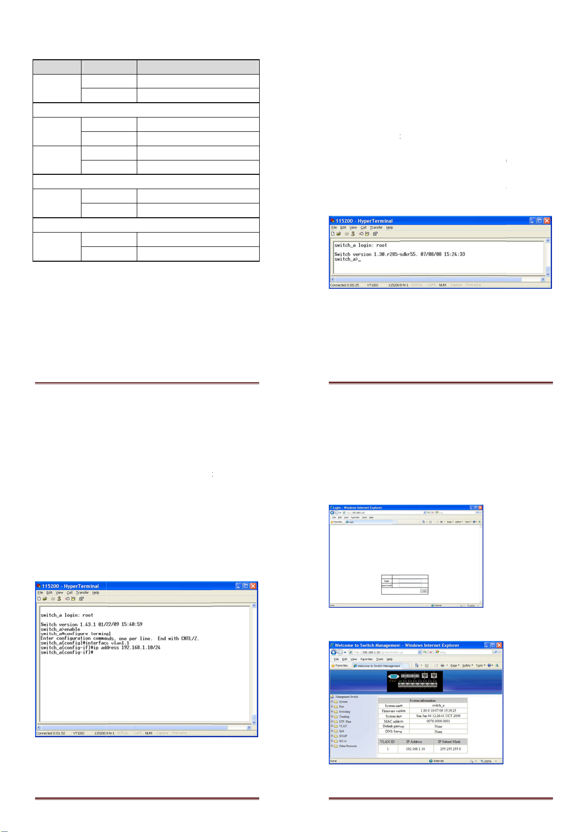
1. Login the switch:
2.
Specify the default IP address (192.168.1.10) of
the web browser. A login window will be shown as below:
3.
Enter the factory default login ID: root.
4.
Enter the factory default password (no password).
5.
Then click on the “Login” button to log on to the switch.
Note: Please refer to User Man
Web Configuration
Specify the default IP address (192.168.1.10) of
the web browser. A login window will be shown as below:
Enter the factory default login ID: root.
Enter the factory default password (no password).
Then click on the “Login” button to log on to the switch.
Note: Please refer to User Man
ual for more detailed information
Page 7
the switch in
the web browser. A login window will be shown as below:
Enter the factory default password (no password).
Then click on the “Login” button to log on to the switch.
ual for more detailed information

Other manuals for Infinity IES-1085

1

Other LevelOne Switch manuals

LevelOne FGP-1031 User manual

LevelOne

LevelOne FGP-1031 User manual

LevelOne GTP-2881 User manual

LevelOne

LevelOne GTP-2881 User manual

LevelOne GES-1650 User manual

LevelOne

LevelOne GES-1650 User manual

LevelOne 1650 User manual

LevelOne

LevelOne 1650 User manual

LevelOne GSW-5150 User manual

LevelOne

LevelOne GSW-5150 User manual

LevelOne GTL-2880 User manual

LevelOne

LevelOne GTL-2880 User manual

LevelOne ViewCon KVM-0850 User manual

LevelOne

LevelOne ViewCon KVM-0850 User manual

LevelOne IGP-1271 Operator's manual

LevelOne

LevelOne IGP-1271 Operator's manual

LevelOne FSW-0808TX User manual

LevelOne

LevelOne FSW-0808TX User manual

LevelOne FGP-2472 User manual

LevelOne

LevelOne FGP-2472 User manual

LevelOne GTP-2871 User manual

LevelOne

LevelOne GTP-2871 User manual

LevelOne Infinity IES-0510 User manual

LevelOne

LevelOne Infinity IES-0510 User manual

LevelOne KVM-0306 User manual

LevelOne

LevelOne KVM-0306 User manual

LevelOne SoHoCon FSW1602TX User manual

LevelOne

LevelOne SoHoCon FSW1602TX User manual

LevelOne GSW-2600TXM User manual

LevelOne

LevelOne GSW-2600TXM User manual

LevelOne FGP-1031 User manual

LevelOne

LevelOne FGP-1031 User manual

LevelOne GES-1652 User manual

LevelOne

LevelOne GES-1652 User manual

LevelOne GES-2451 User manual

LevelOne

LevelOne GES-2451 User manual

LevelOne GES-2105P Programming manual

LevelOne

LevelOne GES-2105P Programming manual

LevelOne GEP-2841 User manual

LevelOne

LevelOne GEP-2841 User manual

LevelOne Infinity IES-1082 User manual

LevelOne

LevelOne Infinity IES-1082 User manual

LevelOne FSW-0803TX User manual

LevelOne

LevelOne FSW-0803TX User manual

LevelOne POH-0850TX User manual

LevelOne

LevelOne POH-0850TX User manual

LevelOne GSW-1676 User manual

LevelOne

LevelOne GSW-1676 User manual

Popular Switch manuals by other brands

Siemens SIMATIC NET RUGGEDCOM RX1511 installation manual

Siemens

Siemens SIMATIC NET RUGGEDCOM RX1511 installation manual

H3C S5830V2 series Configuration guide

H3C

H3C S5830V2 series Configuration guide

Honeywell 968XTP installation instructions

Honeywell

Honeywell 968XTP installation instructions

TP-Link tapo S505D user manual

TP-Link

TP-Link tapo S505D user manual

Pepperl+Fuchs Vibracon LVL-M H Series instruction manual

Pepperl+Fuchs

Pepperl+Fuchs Vibracon LVL-M H Series instruction manual

Magnimage V8 Series user manual

Magnimage

Magnimage V8 Series user manual

Vixen Horns VXA7115-3 installation guide

Vixen Horns

Vixen Horns VXA7115-3 installation guide

SignaMax 065-7345 user guide

SignaMax

SignaMax 065-7345 user guide

NETGEAR GS504T - Switch installation guide

NETGEAR

NETGEAR GS504T - Switch installation guide

Endress+Hauser Liquiphant FTL31 operating instructions

Endress+Hauser

Endress+Hauser Liquiphant FTL31 operating instructions

ZyXEL Communications MGS-3712/MES-3728 user guide

ZyXEL Communications

ZyXEL Communications MGS-3712/MES-3728 user guide

D-Link xStack DGS-3400 Series user manual

D-Link

D-Link xStack DGS-3400 Series user manual

Allnet ALL4806W user manual

Allnet

Allnet ALL4806W user manual

ZyXEL Communications GS1920-48HP Release Note/Manual Supplement

ZyXEL Communications

ZyXEL Communications GS1920-48HP Release Note/Manual Supplement

Maiwe MIEN1203 user manual

Maiwe

Maiwe MIEN1203 user manual

Linksys LGS308 user guide

Linksys

Linksys LGS308 user guide

Raritan MCC4 user manual

Raritan

Raritan MCC4 user manual

Mellanox Technologies Spectrum SN2100 Quick installation guide

Mellanox Technologies

Mellanox Technologies Spectrum SN2100 Quick installation guide

manuals.online logo
manuals.online logoBrands
  • About & Mission
  • Contact us
  • Privacy Policy
  • Terms and Conditions

Copyright 2025 Manuals.Online. All Rights Reserved.