HITROL HLT-1112 User manual

이 부분이 상부 방향으로 설치할 것.
(This part will install
in the up direction)
HITROL CO., LTD.
Always The Best Solution by
HEAD OFFICE, FACTORY, R&D INSTITUTE
141 Palhakgol-Gil, Jori-Eup, Paju-Si,
Gyeonggi-Do, Korea
Tel. : +82-31-950-9700 Fax : +82-31-943-5600
Website : www.hitrol.com
INSTRUCTION MANUAL
MAGNETIC COUPLING TYPE TANK LEVEL GAUGE
HLT-1112 & HLT-1212
Doc. No. : HLT-1112_M_Eng_2016, Rev. 0
Issued Date : 2016. 01

2ALWAYS THE BEST SOLUTION HITROL CO., LTD
Overview
Features
Operang Principle
General Specicaon
Applicaon
System Composion and Details of Parts
3
3
3
4
4
• HLT-1112 / Screw Type
• HLT-1212 / Flange Type
• Details of Parts
5
6
7
Installaon
* Condion for the installaon and adjustment
* Recommended Installaon Process
1. Installaon of Measuring Tape on Elbows
2. Installaon of Measuring Tape and Spring Motor (Inside the Tank)
3. Installaon of Measuring Tape (Weight Side)
4. Reference for the Boom Anchor Installaon
8
8
8
9
9
2.1 Installaon of Measuring Tape
2.2 Installaon of Spring Motor
* Assembly Inspecon
3.1 Folding of Measuring Tape
3.2 Connecon of the measuring tape to the weight
10
11
11
11
11
Direcon for the Installaon
Operang Check
Note
Warranty
12
12
12
12
Table of Contents
3ALWAYS THE BEST SOLUTION HITROL CO., LTD
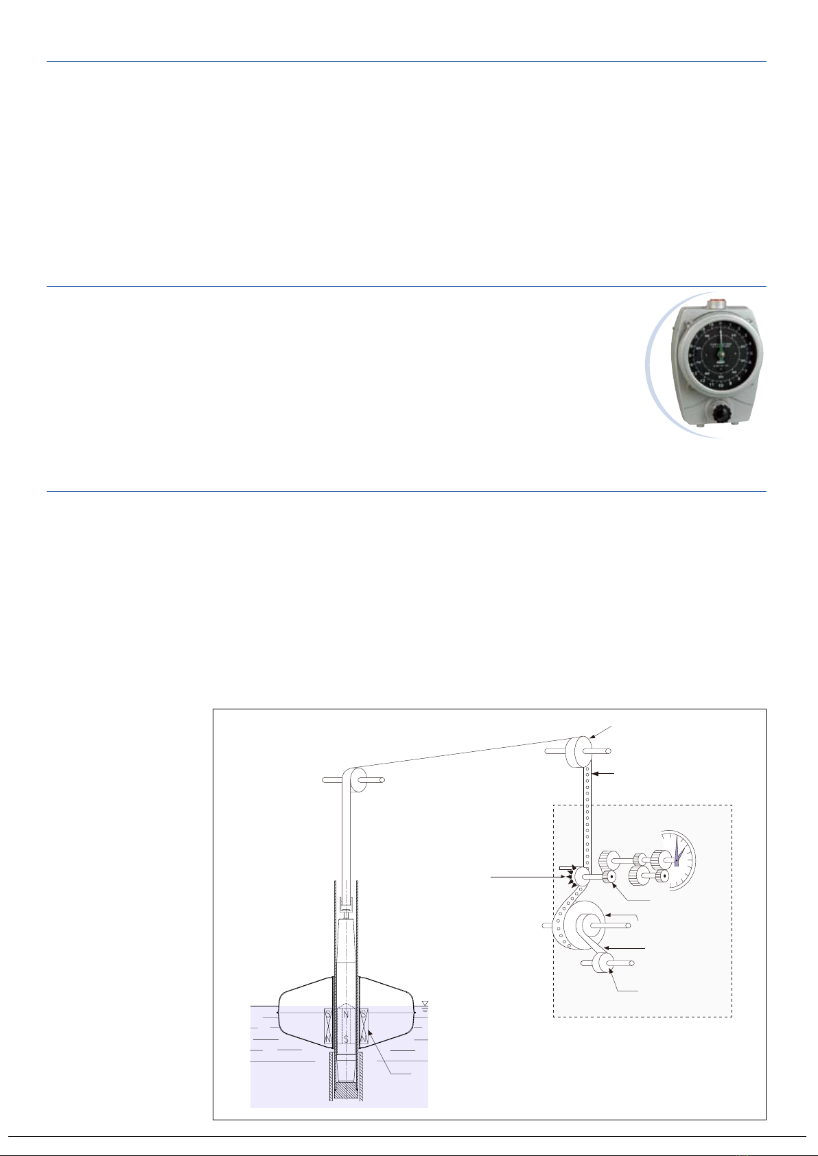
HLT-1112 (HLT-1212) is a magnec coupling type oat level gauge which measures
liquid level in a tank, by movement of a weight in a guide pipe according to a
movement of a oat, using a constant spring. Convenonal level gauge is hard to be
applied for corrosive and/or toxic liquids due to a corrosive vapor which is develped
in a tank and comes up along a guide pipe to gauge head, can corrode inside
components in a gauge head. On the other hand, magnetic coupling type float
level gauge is a closed type and prevent an inow of vapor into a guide pipe so it is
suitable for corrosive and/or toxic liquids.
• Applicable to a tank which has a pressure (Max. 5kg/cm2).
• Measurement in mm using spring balance
• Simplified design, high accuracy and durability
• Operating checkup using a Drive Checker
• Easy installation and maintenance
• Option for remote indication, control and switch for alarm
• Large scale dial enables legible indication even at a distant location.
The float in a tank floats on the surface of the liquid at the point which the float
weight and buoyancy are in equilibrium, and the magnet in the float sticks to the
magnetic in the weight which is installed in a guide pipe because the polarity of
them is contrary. When the liquid level changes, weight moves according to the
movement of the float and spring motor adjusts the measuring tape to maintain
the float position on the surface of the liquid. The measuring tape has a series of
holes set at regular intervals and as the tape rotates the sprocket, it in turn operates
the display indicator. The position of the measuring tape holes on the sprocket
compensates for the tape weight and prevents the tape from slipping.
Sheave Elbow
Measuring Tape
Gauge Head
Sprocket Wheel
Indicator
Gearing
Mechanism
Tape Drum
Spring Motor
Spring Motor
Drum
Magnet
OVERVIEW
FEATURES
OPERATING PRINCIPLE
4
ALWAYS THE BEST SOLUTION HITROL CO., LTD
APPLICATION
This tank level gauge can be used to measure and indicate liquid level in various
industries such as oil refineries, petrochemical, food, chemistry and water
treatment, etc. Details are as below.
• Oil refinery : Crude oil, gasoline, heavy oil, kerosene, naphate, organic liquids,
inorganic liquids, asphalt and sulfur, etc.
• Petrochemistry : Benzol, toluene, xylene, methanol and ethanol, etc.
• Food industry : Beer, whisky, soy sauce, etc.
• Chemistry : Caustic soda, hydrochloric acid and sulfuric acid, etc.
• Power plant : Heavy oil, water reservoir and distilled water, etc.
• Water treatment : Waterworks and sewage system, waste liquid, drinking water
and elevated water tanks, etc.
Type Magnec Coupling Type (Screw Type : HLT-1112 / Flange Type : HLT-1212)
Installaon Top or Side Mounng
Indicator 2-Points Dial
Ambient Temperature -20oC ~ 60oC
Fluid Temperature Max. 150oC
Operang Pressure Up to 5kg/cm2
Enclosure Weather Proof (IP65)
Applicaon Liquid
Measuring Range 2.5M / 5M
Specic Gravity 0.6 ~ 2.0
Accuracy ±2mm
Combinaon Transmier HAT-1000(-Ex), HAT-5000(-Ex)
Process Connecon Size Screw Type : 2" Flange + PT 1-1/2"(F) Socket (Std.)
Flange Type : 2" Flange (Std.)
● PARTS LIST
Part Name Material Q'ty Remark Scope
Head AL.C 1 Screw Type : PT 1-1/2"(F) (Std.)
Flange Type : ANSI 1-1/2" 150# RF (Std.)
Hitrol Scope
Sheave Elbow AL.C (Std.)
304 SS (Opt.)
2Screw Type : PT 1-1/2"(F) (Std.)
Flange Type : ANSI 1-1/2" 150# RF (Std.)
Measuring Tape 316 SS 1
Guide Pipe 304 SS (Std.)
316 SS (Opt.) 1
Float 304 SS (Std.)
316 SS (Opt.) 1
Weight 304 SS 1
Pipe Support C.S (Std.)
304 SS (Opt.)
nRequired quanty depends on the tank height.
Gauge Support C.S (Std.)
304 SS (Opt.) 1
Seal Pipe - - 1-1/2" Pipe (Std.)
User ScopeBoom Anchor - - Refer to details of parts on page 7.
Nozzle Part - - Refer to connecon part on page 7. [ANSI 2" 150# RF (Std.)]
GENERAL SPECIFICATION

5ALWAYS THE BEST SOLUTION HITROL CO., LTD
SYSTEM COMPOSITION AND DETAILS OF PARTS
HLT-1112 : SCREW TYPE

6
ALWAYS THE BEST SOLUTION HITROL CO., LTD
HLT-1212 : FLANGE TYPE

7
ALWAYS THE BEST SOLUTION HITROL CO., LTD
DETAILS OF PARTS
Head Parts
Connecon Part
Material : Aluminium
<Screw Type> <Flange Type>
Connecon Type
• Screw : PT 1-1/2"(Std.), NPT 1-1/2", PF 1-1/2" and other
• Flange : ANSI, JIS and DIN
Material
• 304SS, 316LSS and other
Connecon
Pipe (User Scope)
Connecon
Socket
Flange for
Guide Pipe
Nozzle Flange
(User Scope)
Guide Pipe
Connecon Pipe
w/Flange
(User Scope) Flange for
Guide Pipe
Nozzle Flange
(User Scope)
Guide Pipe
• Sheave Elbow (AL.C) • Float
• Boom Anchor
(User Scope)
• Weight
• Gauge Support
8ALWAYS THE BEST SOLUTION HITROL CO., LTD
[Fig.1]
Elbow-B
Elbow-A
(Tank Side)
(Gauge Side)
[Fig.2]
Measuring Tape
Elbow-B
(Gauge Side)
Elbow-A
(Tank Side)
1. INSTALLATION OF MEASURING TAPE ON ELBOWS
INSTALLATION
* INSTALLATION PROCESS (RECOMMENDED)
(Aer installaon of Guide Pipe, Float and Boom Anchor to inside the tank),
1. Pass the measuring tape through the 90o sheave elbows.
2. Install the measuring tape aer disassembly of the gauge head.
3. Install the spring motor to spring loaded drum (1) and (2) in the gauge head.
4. Connect the weight.
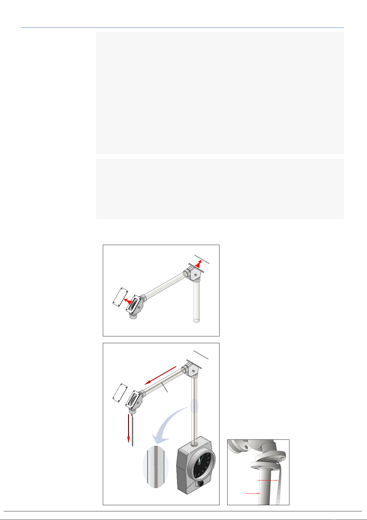
Before installation of measuring tape
on elbows, install the seal pipes as
shown in [Fig.1] in advance. But, install
the seal pipe on nozzle (tank) side aer
installation of measuring tape and
weight.
Unfasten the bolts on covers of Elbow-A
and Elbow-B and open covers.
* CONDITION FOR THE INSTALLATION AND ADJUSTMENT
1. Seal pipe and boom anchor should be prepared by user.
2. Installaon of elbow and seal pipe in advance is ne. However, install the
seal pipe on nozzle side to the elbow aer installaon of measuring tape and
weight (Refer to page 8 and 11).
3. Inside the tank should be empty and there should be nothing which can
disturb the installaon of the level gauge.
4. Tank nozzle should be installed in advance, suitable with our connecon
part and it should not be dangerous for work inside the tank.
5. There should be no leakage of the medium.
6. The environment for performing of the installaon and adjustment safely
should be prepared.
Pass one end of measuring tape (not
perforated) from Elbow-B to the
direcon of Elbow -A as shown in [Fig.2]
and make sure that the measuring tape
with hole (perforated) side should be
positioned in a gauge head, not in a
tank.
If seal pipe on nozzle side is already
installed, pull out the measuring tape
•
•
•
•
through elbow
and seal pipe
aer unfastening
of them for the
installaon of the
weight. (Refer to
le image)
Seal Pipe
Measuring Tape

9ALWAYS THE BEST SOLUTION HITROL CO., LTD
elbow to inside of the tank through the hole of connecon.
4) Pass the measuring tape through the space between the sprocket and tape
guide as shown in Fig. 3 with a careful aenon for the xing of spikes on
the sprocket to the holes on the measuring tape. The distance between
the sprocket and tape guide can be adjusted with a screw.
5) Fix the end of measuring tape to the locking screw with bolt.
6) Aer xing of measuring tape, wind it counterclockwise to give a tension
to the measuring tape. The measuring tape without holes (not perforated)
should not be posioned in the gauge head.
2. INSTALLATION OF MEASURING TAPE AND SPRING MOTOR (INSIDE THE TANK)
2-1. Installaon of Measuring Tape
1) Open the back cover of gauge
head.
2) Disassemble the inside Spring
Loaded Drum (1) and (2) in the
gauge head rst.
3) Pull down the measuring tape
which is out from the upper
Tape Guide
Sprocket
Spring Loaded Drum (1)
Spring Loaded Drum (2)
Tape Storage Sheave
Measuring Tape
[Fig.3]
Measuring Tape
Sprocket
Tape guide
screw
2mm
Sprocket
Tape drum
Tape locking screw
Tape guide
Spring loaded
drum (smaller)
Locking screw
Spring loaded
drum (larger)
10ALWAYS THE BEST SOLUTION HITROL CO., LTD
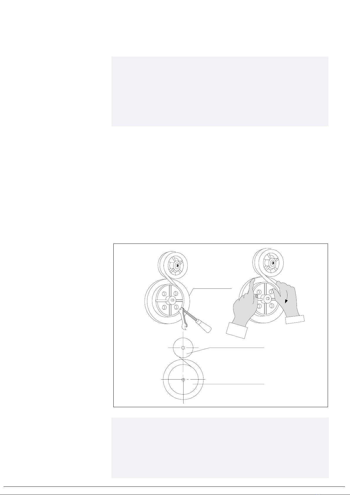
2-2. Installaon of Spring motor
The spring motor should be set aer the measuring tape has been stretched
in posion.
1) Put disassembled spring loaded drum (1) and (2) in places.
2) Fix the spring on spring loaded drum (1) to the locking screw on spring
loaded drum (2) with a bolt. The spring should be wound clockwise so
locking screw should be posioned right side when the spring is xed to
the spring loaded drum (2) as shown in Fig. 4.
3) Wind the spring clockwise about two or three turns in order to prevent the
derailment of the spring from spring loaded drum.
4) Aer winding of spring, x the spring loaded drum (2) to the tape storage
sheave.
5) Complete the installaon of spring motor aer xing by upper locking ring.
[Fix all spring loaded drum (1) and (2)]
* PRECAUTION :
• When the spring motor gets out of the spring loaded drum (larger) or
excessive force is applied to it, it produces non-uniform torque which
may be cause of erroneous indication.
• At the stage to wind the spring motor from the smaller drum to the
larger one, do not leave your hand from the larger drum until the
measuring tape is tensed finally.
* ASSEMBLY INSPECTION :
• Aer the installaon of measuring tape and spring motor is nished,
pull out the measuring tape which is out from gauge head and check
if there is a jam or derailment. When the tape is loosed, the spring
should be wound. If there is a jam or derailment aer pulling out the
measuring tape, adjust nely using a screw.
Spring loaded drum (1)
Spring loaded drum (2)
(smaller)
(larger)
Locking screw
screw + nut
[Fig.4]

11ALWAYS THE BEST SOLUTION HITROL CO., LTD
1 2 3 4
3. INSTALLATION OF MEASURING TAPE (WEIGHT SIDE)
4. REFERENCE FOR THE BOTTOM ANCHOR INSTALLATION
1. Boom Anchor is a user scope so it should be prepared by user.
2. It is recommended to install the boom anchor before installaon of tank level
gauge in order to prevent a change of it's locaon.
3. It is recommended to put the boom anchor to the boom of our guide pipe
rst and adjust the upper posion. Aer xing of the upper posion, x the
boom anchor to the tank boom.
1. Connect the folded measuring tape to the weight as above. The length of bolt
should not be over 10mm because long bolt can cause a malfuncon of the
gauge.
2. Put the weight connected with the measuring tape to inside the tank through
the seal pipe.
3. Aer put of weight, check whether the measuring tape gets out of the roller
or not. If not, complete the installaon of measuring tape aer assembly of
elbow cover.
3-1. Folding of Measuring Tape
Fold the measuring tape on Elbow-A as below order.
•
* PRECAUTION :
• Temporarily fixing the measuring tape on upper elbow
suitable for each site condition.
• Take care not to bend or give damages to the measuring
tape when folding of it.
3-2. Connection of the measuring tape to the weight
Folding
Folding
1 2 3 4

12ALWAYS THE BEST SOLUTION HITROL CO., LTD
WARRANTY
Warranty and Aer Sales Service
Warranty of the product is 2 years after shipment and it can be warranted for
malfunction occurred under use in normal condition, but it maybe charged
regardless of warranty period in case that after sales service is requested not for
malfunction of the product.
After sales service can be requested at our website or to our factory.
Headquarter ∙ Factory ∙ R&D Center
Address : 141 Palhakgol-Gil, Jori-Eup, Paju-Si, Gyeonggi-Do, Korea
Tel. : +82-31-950-9700
Fax : +82-31-943-5600
OPERATING CHECK
The tank level gauge can be used right aer properly installaon as instructed and
specicial operating procedure or order is not required. Operating can be checked
using a drive checker as below.
Handling of Drive Checker
The drive checker is used for confirming of
level indicaon and operaon of the tank level
gauge at the me of calibraon.
1. If the checker knob is turned clockwise
about 90o (1/4 turn), the oat is slightly
lied.
DIRECTION FOR THE INSTALLATION
1. Use the galvanized or stainless steel pipe for outside tank.
2. Non linearity due to exure of pipe must be limited within ±5mm.
3. If the medium in the tank is highly corrosive, use the pipe which is lined.
4. The oat should be posioned as far away from the liquid inlet or tank srrer as
possible. This will limit the eects of turbulence and prevent ow directly hing
the oat.
5. Take care not to fold or kink the measuring tape.
6. During the installaon, take care not to allow the measuring tape to get out of the
sheave elbows or balancer roller and check if it is posioned properly in a groove
of them.
7. Do not loosen or unfasten the thumb screw. Otherwise, spring motor winds
rapidly and it can bring an accident.
Check Handle
Gauge Head
Drive Checker
NOTE
Above information should be fully acquainted by user and the temperature of
the medium in a vessel should not be exceed max. +150oC. And also, ambient
temperature should not be exceed -20 ~ +60oC.
2. Above handling of drive checker can conrm the operang of each parts through
the indicator.
This manual suits for next models
1
Table of contents
Other HITROL Measuring Instrument manuals


