manuals.online logo
Brands
  1. Home
  2. •
  3. Brands
  4. •
  5. GANN
  6. •
  7. Measuring Instrument
  8. •
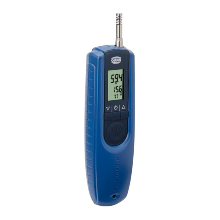
  9. GANN HYDROMETTE HB 30 User manual

GANN HYDROMETTE HB 30 User manual

GANN HYDROMETTE HB 30
Operating Instructions
1
Table of Contents
Page
Description of the measuring instrument .....................................................................3
Measuring ranges ....................................................................................................4
Battery, Dimensions and admissible ambient conditions ......................................... 5 - 6
Safety directions .............................................................................................. 7 - 8
Instructions for wood moisture measurement ....................................................... 9 - 10
Use of measuring electrodes for wood moisture measurement ............................. 11 - 14
General directions to wood moisture measurement ............................................. 15 - 17
Instructions for structural moisture measurement ...................................................... 18
Use of measuring electrodes for structural moisture measurement ........................ 19 - 24
Equilibrium moisture - general information .......................................................... 25 - 26
Comparison graph - Air humidity - wood moisture content -
structural moisture ................................................................................................. 27
Equilibrium moisture values .............................................................................. 28 - 29
Conversion graphs for structural moisture measurement ...................................... 30 - 36
Use of active electrodes MB 35, B 50 and B 60 ................................................. 37 - 43
Instructions for infrared surface temperature measurement .................................. 44 - 49
Description of measuring electrodes................................................................... 50 - 59
Warranty .............................................................................................................. 60
Declaration of conformity ....................................................................................... 61
2
3
Technical Specifications - Hydromette HB 30
(1) BNC Connection Socket for connection of electrodes designed for testing wood
and set building materials
(2) 7-pin Connection Socket for connection of the active electrodes MB 35, B 50, B
60
and IR 40
(3) LCD Readout for all measurements
(4) Selector Switch »position 2 and 3«
for automatic correction of readings according to the
species of wood to be measured (see separate table of
wood species)
»position B«
for measurement of set building materials according to
the
resistance measuring method
»position M«
for measurements using the active electrodes B 50,
B 60, MB 35 and IR 40.
»position Batt«
for battery check.
(5) Measuring Key ON/OFF
4
Measuring ranges
Wood Moisture, position »2-3«: 4 - 30 % m.c.
Structural Moisture 1, position »B«: 0 - 80 digits with graphs for convert-
ing
readings into percent of
moisture for various building
materials
Structural Moisture 2, position »M«: 0 - 199 digits non-destructive measurement
with active electrode B 50 or
B 60
0.3 - 8.5 % of dry weight non-
destructive
measurement with active
electrode B 50 and B 60 by
conversion table
0.3 - 6.5 % CM non-destructive measurement
with active electrode B 50
and
B 60 by conversion table
2 - 8 % of dry weight with active
electrode MB 35, non-
destructive surface measure-
ment of concrete
5
Temperature, position »M«: -20.0 - 200 °C with infrared sensor IR 40.
If the measured value exceeds the measuring capacity, the figure »1« appears on the left side
of the display screen (3).
Battery Check
Set selector switch (4) to position »Batt« and press measuring key (5). The reading displayed
should be higher than 7.5 digits. If it is 7.5 digits or lower, the battery is exhausted and
should be replaced or recharged if a rechargeable battery is being used. The cover of the bat-
tery compartment can be lifted by means of a coin inserted into the slot.
It is recommendable to replace or recharge the battery once the reading of the battery check
is between 8.0 and 7.5 digits.
Power Source
The meter is fitted, as standard, with a 9 V dry battery IEC 6 F 22 or IEC 6 LF 22.
It is recommended to use alkali-mangan batteries.
A rechargeable nickel-cadmium battery can be fitted (optional accessory). It can be recharged
from any A.C. lighting supply socket by means of the charging unit supplied with this special
battery.
Calibration
The meter is fitted with an electronic setting device, making manual calibration or adjustment
unnecessary.
6
Dimensions
Plastic casing: Length 140 mm x Width 90 mm x Height 42/50 mm.
Weight: about 230 g without accessory.
Admissible ambient temperatures
Storage: 5 to 40 °C; temporarily -10 to 60 °C not condensing
Operation: 0 to 50 °C, short term -10 to 60 °C not condensing
The meter including accessory must not be stored or used in aggressive air or air contami-
nated by solvents.
The instructions for use of the meter and of the electrodes should be carefully
observed to avoid measuring errors which may occur when trying to simplify the
measuring procedure.
7
Important Safety Directions and General Remarks
The following instructions should be carefully read and understood prior to first use of the
moisture meter. No warranty claim can be accepted for any damage caused by non-
observance of these instructions. The manufacturer can also not assume any responsibility for
incidental or consequential damages.
The instructions for use of the meter and of the electrodes should be carefully observed to
avoid measuring errors which may occur when trying to simplify the measuring procedure.
Make sure in any case prior to drilling holes for measuring probes or before driving
electrode pins into walls, ceilings or floors that this happens away from power
lines, water pipings or other supply pipes.
Using the moisture meter under unfavourable environment conditions should be avoided as
this could result in damages to the sensitive electronic circuitry of the meter itself or to the
measuring sensors.
Unfavourable environment conditions are among other things
 constantly too high an ambient air humidity (>90 % R.H.),
 dust and inflammable gases or vapours as well as air containing solvents,
 ambient temperatures exceeding 50 °C,
 ambient temperatures below the freezing point,
8
 ambient temperature dropping below dew point (formation of condensate).
When using the measuring probes and connecting to or disconnecting them from the measur-
ing instrument do not use force and do not pull on the cable.
The measuring instrument, connecting cable and measuring probes must not be used or
stored in aggressive or air containing solvents.
Static Electricity - At low air humidity circumstances such as friction during timber handling or
highly insulated surroundings may cause static electricity of very high voltages. This may re-
sult not only in fluctuating or negative readings, but can also destroy transistors and ICs used
in manufacturing the moisture meter.
The operator too may contribute by his clothing or shoes made of man-made fibre to build up
a static charge. The results can markedly improved, if the operator stands perfectly still and
avoids moving the meter and the measuring cable while taking the reading.
Frozen wood with moisture content in excess of 20 % cannot be measured.
The information and tables on admissible or usual moisture conditions as well as the general
terms and definitions contained in the instructions were taken from the specialist literature.
The manufacturer or supplier of the measuring instrument cannot be held responsible for the
correctness of this information.
The conclusions to be drawn from the measurement results by each user are governed by the
individual circumstances and experiences and knowledge gained in the course of his profes-
sional practice.
The measuring instrument meets the stronger demands laid down in class B of the pertinent
regulations for interference emission and may, therefore, be used also in living areas.

9
The measuring instrument and its standard and optional accessory must only be used as de-
scribed in this manual.
In view of the electromagnetic compatibility and the reliability of measurement, only the stan-
dard and optional accessory described in this manual must be used with the measuring in-
strument.
Operating Instructions for Wood Moisture Measurement
using measuring electrodes M 18, M 20, and M 20-OF 15
Set selector switch (4) to position (2 or 3) stated in the table of wood species for the species
to be tested. Only species classified in group 2 and 3 can accurately be measured.
Connect measuring electrode to the meter socket (1) by means of the measuring cable MK 8.
Drive-in, stick-in or press the electrode onto the wood to be measured.
Press measuring key (5) and read off result displayed by the LCD readout as soon as the read-
ing has stabilised. Press measuring key no more than three seconds.
10
11
Handling of the Electrodes for Wood Moisture Measurement
Connection of the Electrodes
The meter can be used with different types of measuring electrodes according to the individ-
ual application. The electrodes M 6, M 18, M 20, and M 20-HW are connected to the meter
socket (1) by means of the measuring cable MK 8. On the meter side, this cable is fitted with
a BNC plug. Turn clockwise to lock it. To disconnect, turn notched fastening ring anti-
clockwise. Do not use force and do not pull on the cable.
Grain Direction
GANN wood moisture meters have been calibrated for taking readings with electrode pins
driven into the test sample across the grain. As the electrical resistance is greater across the
grain than parallel to the grain, too high a reading will be obtained if the electrode pins of
GANN meters are applied parallel to the grain. The effect can be neglected at readings below
10 % m.c., whereas around 20 % m.c. the meter will read about 2 % m.c. higher.
Thickness of Wood
Electrode with pins having a penetration of 10 mm can be used on wood up to 30 to 40 mm
thick, whereas pins with a penetration of 17 mm are designed for wood thicknesses between
50 and 65 mm. For thicker boards or planks, the ram-in electrode M 18 should be used which
permits the use of pins with a penetration depth up to 54 mm.
12
For stock with uniform moisture content, non-insulated pins can be used, whereas for all
other applications insulated pins making contact only with their uncoated tip having a uniform
contact area with the wood, regardless of the penetration depth, should be used. Any change
in meter readings taken with insulated pins at different penetration depths clearly reflect an
actual change in moisture content representing the existing moisture gradient.
Drive-in Electrode M 20
Drive the electrode into the wood with the needles across the grain (the electrode body is
made of impact-resistant plastic). When withdrawing the electrode, the pins can be loosened
by slight sideways rocking movements across the grain.
For determining the average moisture content, the pins have to be driven to a depth of
approx. 1/4 to 1/3 of wood thickness.
When the M 20 electrode is supplied with the meter as initial equipment, 10 spare pins 16
and 23 mm long are included in the delivery. They are suitable for testing wood up to 30 mm
and 50 mm thick respectively.
If thicker boards or planks are to be measured, the needles can be replaced by longer ones.
Naturally, the liability to breakage and/or bending increases with the length of the pins, espe-
cially when withdrawing them. Therefore, it is recommended to use the ram-in electrode M 18
for testing thicker wood.
The cap nuts should be tightened by means of a spanner. Loose needles may easily break.
13
Surface Electrodes M 20-OF 15
Surface measurements should only be taken when the wood moisture content is below 30 %
m.c. For surface measurements on already machined stock, the two hexagon cap nuts have
to be unscrewed and replaced with the surface measuring caps. For measurement, the two
contact pads have to be pressed across the grain onto the stock to be measured. The measur-
ing depth is about 3 mm, so when testing thinner stock several boards have to be laid on top
of one another for measurement. Do not measure thin boards on metal bases.
Wood particles adhering to the measuring surface should be removed at regular intervals. If
the flexible plastic pads are damaged, new ones can be ordered (Ref. No. 4316) and stuck on
using a commercially available instant adhesive on cyanate basis.
Ram-in Electrode M 18
The two needles of the ram-in electrode have to be driven to the required measuring depth,
across the grain, using the sliding hammer. For determining the average moisture content, the
same measuring depth as described with electrode M 20 is required.
The pins must not be driven into the wood until the cap nuts are in touch with the
wood to be measured to avoid a possible damage to the electrode. Stop hammer-
ing when the gap between the cap nuts and the wood is still about 5 mm.
The needles are withdrawn by striking upwards with the sliding hammer. Prior to a series of
measurements, the cap nuts should be tightened by means of a spanner. Loose needles may
easily break.
14
When the M 18 electrode is supplied with the meter, 10 spare pins 40 mm and 60 mm long
(without insulated shank) are included in the delivery. They are suitable for measuring wood
up to 120 mm and 180 mm thick respectively. For testing timber with higher shell m.c. than
core m.c., e.g. if boards were exposed to rain, electrode pins with insulated shank should be
used. They are available in packets of 10 pins and in lengths of 45 mm (Ref. No. 4550) and 60
mm (Ref. No. 4500).
Test Standard for Wood Moisture Measuring Curcuit
The test standard (Ref. No. 6070) permits to check the meter as well as the connection cable
and the measuring electrodes M 18 and M 20 both in respect to proper function and accurate
readings.
To do so, connect the cable to the meter and insert the two plugs of the cable into the bush-
ings of the test standard. If the measuring electrode is to be included in the check, connect
electrode to the cable and insert the two electrode pins into the bushing of the test standard.
Set wood species selector (4), contrary to the indication on the test standard, to position 3
and press measuring key (5). The meter should read 18.1 %. The admissible tolerance is ±0.5
%. The meter and the test standard should have a temperature of about 20 °C.
15
Effects of Wood Preservers
Treatment of wood with organic preservers or impregnating agents have, in general, little ef-
fect on the meter readings. Treatment with preservatives containing salts or other inorganic
constituents that change the conductivity of wood, however, has a great effect on the accu-
racy of the readings and as it is erratic, a suitable table correction cannot be provided.
Moisture Checks on Plywood
Some of the various types of glue used in the manufacture of plywood have a lower electrical
resistance than the wood. This will affect the accuracy of electrical resistance moisture me-
ters when the electrode pins get in touch with a glue line. The meter will then show too high
a moisture content.
To find out whether a conductive glue has been used in manufacturing the plywood to be
tested, drive the electrode pins to a depth of no more than half the thickness of the first ply
and read the result. Then drive the pins further into the plywood until they come in contact
with the first glue line. If the reading now displayed is not noticeable higher than before, the
glue may be considered to have no effect on the accuracy of the meter readings.
16
Static Electricity
At wood moisture contents below 10 %, circumstances such as low air relative humidity, fric-
tion during timber handling or highly insulated surroundings may cause static electricity of
very high voltages. The operator too may contribute, e.g. by his clothing or shoes made of
man-made fibre, to build up a static charge. This may result not only in fluctuating or negative
readings, but can also destroy transistors and integrated circuits used in manufacturing the
moisture meter.
The results can be markedly improved, if the operator stands perfectly still and avoids moving
the meter and the measuring cable while taking the reading.
Especially at the outlet of veneer dryers, very high static charges have to be expected. There-
fore, moisture measurements of dried veneer should be made only after the static charge has
been sufficiently reduced, what can be sped up by employing suitable grounding measures.
Wood Moisture Equilibrium - Equilibrium Moisture Content
When storing wood for a sufficiently long space of time in a constant ambient atmosphere, it
will adopt the moisture content that corresponds to this climate which is called Wood Mois-
ture Equilibrium.
17
Once the wood has reached its moisture equilibrium, it will neither give off moisture nor ab-
sorb it from the air, unless the ambient atmosphere changes. The following table shows some
moisture equilibrium values which wood adopts at the various conditions specified.
Wood Moisture Equilibrium
Air Temperature in °C
10° 15° 20° 25° 30°
Air relative
humidity
Wood Moisture Content
20% 4,7% 4,7% 4,6% 4,4% 4,3%
30% 6,3% 6,2% 6,1% 6,0% 5,9%
40% 7,9% 7,8% 7,7% 7,5% 7,5%
50% 9,4% 9,3% 9,2% 9,0% 9,0%
60% 11,1% 11,0% 10,8% 10,6% 10,5%
70% 13,3% 13,2% 13,0% 12,8% 12,6%
18
80% 16,2% 16,3% 16,0% 15,8% 15,6%
90% 21,2% 21,2% 20,6% 20,3% 20,1%
Operating instructions for moisture measurement
of building materials according to the resistance method
Set selector switch (4) to position »B«.
Connect selected measuring electrode to the meter socket (1) by means of the measuring ca-
ble MK 8 and press or stick electrode pins into the material to be measured.
Press measuring key (5) and read off result displayed by the LCD readout (3) in digits.
Convert reading into per cent of moisture by means of scale graphs listed at the end of this
section.
Connection of the Electrodes
Different electrodes can be used with the meter depending on the material to be tested. The
electrodes are connected to the meter socket (1) by means of the measuring cable MK 8.
19
On the meter side, this cable is fitted with a BNC plug. Turn clockwise to lock it. To discon-
nect,
turn notched fastening ring anti-clock- wise and draw off plug.
Do not use force and do not pull on the cable.
Testing Set Building Materials
For testing soft building materials, the drive-in electrode M 20 should be used, whereas hard
building materials such as concrete and cement flooring are to be measured with the stick-in
electrodes M 6 or M 21/100, using contact paste.
For penetration measurements, up to a depth of 250 mm, on concrete or masonry, the special
electrodes M 21/250 are available.
Special measurement caps type M 20-OF 15 are available for surface measurements (e.g. on
concrete, etc.). They can be used only in conjunction with the electrode M 20.
Drive-in Electrode M 20
For penetration measurements, up to a depth of 70 mm, on soft, set building materials (gyp-
sum, plaster, etc.), drive electrode pins into the material to be tested (the electrode body is of

Other GANN Measuring Instrument manuals

GANN HYDROMETTE BL Compact TF-IR 2 User manual

GANN

GANN HYDROMETTE BL Compact TF-IR 2 User manual

GANN HYDROMETTE BL COMPACT User manual

GANN

GANN HYDROMETTE BL COMPACT User manual

GANN RH-T 37 BL flex User manual

GANN

GANN RH-T 37 BL flex User manual

GANN M 4050 User manual

GANN

GANN M 4050 User manual

GANN Hydromette BL Compact TF-IR User manual

GANN

GANN Hydromette BL Compact TF-IR User manual

GANN Hydromette RTU 600 User manual

GANN

GANN Hydromette RTU 600 User manual

GANN HYDROMETTE BL User manual

GANN

GANN HYDROMETTE BL User manual

GANN HYDROMETTE UNI 1 User manual

GANN

GANN HYDROMETTE UNI 1 User manual

GANN Hydromette BL A plus User manual

GANN

GANN Hydromette BL A plus User manual

GANN HYDROMETTE BL H 41 User manual

GANN

GANN HYDROMETTE BL H 41 User manual

GANN HYDROMETTE BL COMPACT TF 3 User manual

GANN

GANN HYDROMETTE BL COMPACT TF 3 User manual

GANN HYDROMETTE BL LG 17 User manual

GANN

GANN HYDROMETTE BL LG 17 User manual

GANN Hydromette BL H 40 User manual

GANN

GANN Hydromette BL H 40 User manual

GANN HYDROMETTE CH 17 User manual

GANN

GANN HYDROMETTE CH 17 User manual

GANN HYDROMETTE BL Compact TF-IR 2 User manual

GANN

GANN HYDROMETTE BL Compact TF-IR 2 User manual

GANN Hydromette BL UNI 11 User manual

GANN

GANN Hydromette BL UNI 11 User manual

GANN Hydromette BL Compact B 2 User manual

GANN

GANN Hydromette BL Compact B 2 User manual

Popular Measuring Instrument manuals by other brands

Bantam e-STATION TWO-METER quick guide

Bantam

Bantam e-STATION TWO-METER quick guide

Amprobe ECB50A user manual

Amprobe

Amprobe ECB50A user manual

janitza optec UMG-96 operating instructions

janitza

janitza optec UMG-96 operating instructions

Fieldpiece JL3PR user manual

Fieldpiece

Fieldpiece JL3PR user manual

TFA TERRACHECK 30.5044.01 user manual

TFA

TFA TERRACHECK 30.5044.01 user manual

Hanna Instruments Checker HI701 user manual

Hanna Instruments

Hanna Instruments Checker HI701 user manual

Endress+Hauser Cerabar S PMC71 operating instructions

Endress+Hauser

Endress+Hauser Cerabar S PMC71 operating instructions

tams elektronik GBM-8 manual

tams elektronik

tams elektronik GBM-8 manual

AccuTools BluVac LTE user guide

AccuTools

AccuTools BluVac LTE user guide

TESTO 330 instruction manual

TESTO

TESTO 330 instruction manual

PCE Instruments PCE-CSM 6 manual

PCE Instruments

PCE Instruments PCE-CSM 6 manual

Camlab MS-H280-Pro user manual

Camlab

Camlab MS-H280-Pro user manual

PCB Piezotronics J357B12 Installation and operating manual

PCB Piezotronics

PCB Piezotronics J357B12 Installation and operating manual

Rohde & Schwarz TS-PSAM user manual

Rohde & Schwarz

Rohde & Schwarz TS-PSAM user manual

Viso Systems BaseSpion Assembly manual

Viso Systems

Viso Systems BaseSpion Assembly manual

Keysight Technologies N9000B Installation note

Keysight Technologies

Keysight Technologies N9000B Installation note

Bamo MW-10 instruction manual

Bamo

Bamo MW-10 instruction manual

Abtus ABT4650 RouteScan instruction manual

Abtus

Abtus ABT4650 RouteScan instruction manual

manuals.online logo
manuals.online logoBrands
  • About & Mission
  • Contact us
  • Privacy Policy
  • Terms and Conditions

Copyright 2025 Manuals.Online. All Rights Reserved.