Dinghua DH-G200 User manual
1
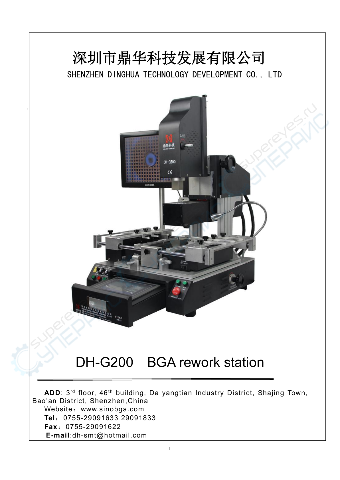
DH-G200 BGA rework station
ADD : 3r d floor, 46th building, Da yangtian Industry District, Shajing Town,
Bao’an District, Shenzhen,China
Website:www.sinobga.com
Tel:0755-29091633 29091833
Fax :0755-29091622
E-mail:dh-smt@hotmail.com
深圳市鼎华科技发展有限公司
SHENZHEN DINGHUA TECHNOLOGY DEVELOPMENT CO., LTD

2
Contents
一Compang Profile……………………………………………...……….3.
二Installation……………………………………………..……………….3
1) Installation………………………………….………..……………..3
2) Power supply…………………………………………..…………..3
三Safety Precaution……………………………………..……………….4
四Structures and Specification………………………………………….5
1) Structures…………………………………………………………..5
2) Function……………………………………………...……………..6
3) Main parameters………………………………………….………..7
五Setting………………………………………………………….……….8
六OPerations………………………………………………………….…15
七Usage of external couple……………………………………………17
八Usual temperature
reference …………………………………………………………20
1) Welding of lead BGA…………………………………………….20
2) Welding of lead-free BGA……………………………………….22
九Precautions……………………………………………………………23

3
Attach: Packing list.
一、Company profile
SHENZHEN DINGHUA TECHNOLOGY DEVELOPMENT CO.,LTD is a professional
manufacturer of welding equipments.Our products: bga rework stations,automatic soldering
machines,automatic screwdriving machines,welding kits and SMT materials etc.Our
mission: “Research as basis, Quality as core, Service as guarantee” . Our goal:
“Professional equipment, quality and service”
To ensure the quality, Dinghua was the first to pass UL、E-MARK、CCC、FCC、CE ROHS
certificates. Meanwhile, to improve and perfect the quality system, Dinghua has passed
ISO、GMP、FCCA、C-TPAT on-site audit certification.
Science and technology are the primary productive forces, with over years of hardworking,
Dinghua has owned core technology of temperature controlled and 38 patents and finished
the development and production of manual, semi-auto and automatic series and realized
the second revolution from traditional hardware combination to integrated control.Our
products have been exported to Europe , America, Southeast Asia, Australia, Africa, the
Middle East, Taiwan and more than 80 countries and regions and established the relatively
sales network and terminal services system.We are becoming the pioneer and guide of
SMT welding industrial and our products have been applied in individual
maintenance,industrial and mining enterprises,teaching and research work,military
manufacturing industry and aerospace industry and so on, which has treed good reputation
among users.
We believe:your successes are our successes,let’s work together and build a
better future!
二、Installation
(A)Installation sites
In order to ensure that the useful life of BGA rework station, installation of repair station must meet
the following conditions:
1.Away from flammable and explosive materials
2.Do not splash water or other liquids
3.Well-ventilated , dry place
4.Stable , flat areas less susceptible to vibration
5.Place less dust
6.Prohibit Placing heavy objects on top of the touch screen
7.Without the influence of air-conditioners, heaters and fans
8.Reserved for 30cm to move and rotate around the upper for the back of rework station
(B)Power supply
INPUT :220AV±10% 50/60HZ
三、Safety precautions
Safety Precautions

4
1.Do not use fans or other devices directly to the repair station hair when it works, otherwise it will
lead to negative differential heating plate surface , burn the workpiece
2.When the machine is on working, high-temperature heating zone can not be any direct contact with
the object , it may cause fire or explosion ,and the PCB workpiece should be placed on the PCB support
shelves
3.Do not shake rework station , and move gently
4.Do not touch the high fever area , otherwise you will burned
5.When turned on, do not use the flammable spray , liquid or flammable gas near the repair station
6.Do not try to modify rework station , otherwise it will cause fire or electric shock
7.Electrical box has the high-voltage components , do not attempt to disassemble
8.If the metal objects or liquids fall into the repair station when it works , immediately disconnect the
power , unplug the power cord until the machine to cool down , then completely remove litter , dirt ; if
dirt left ,there is odor when reboot
9.When abnormal heating or smoking, immediately disconnect the power , and inform the technical
service to repair It needs to disconnect the wires between the electrical boxes and machine parts, and
have to hold the plug, otherwise it leads to poor contact, and does not work
10.Note that the repair station not to press or run over other electrical equipment or power lines or
communication cable , and it may cause device malfunction or cause fire or electric shock
11.Before use the rework station, you must read this manual carefully
四、 Structure and Parameter:
(一) structure:

5
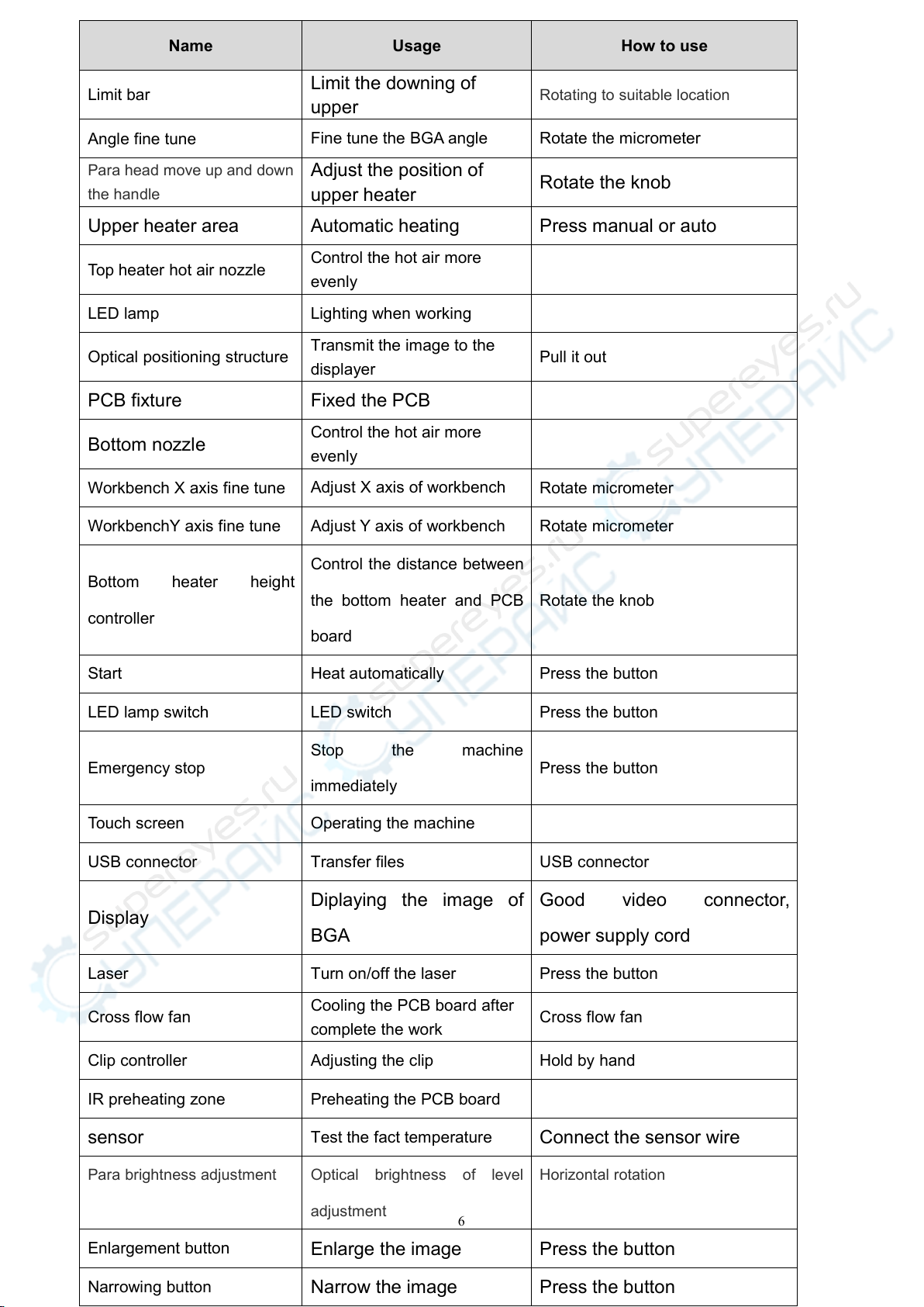
(二) Functions
6
Name
Usage
How to use
Limit bar
Limit the downing of
upper
Rotating to suitable location
Angle fine tune
Fine tune the BGA angle
Rotate the micrometer
Para head move up and down
the handle
Adjust the position of
upper heater
Rotate the knob
Upper heater area
Automatic heating
Press manual or auto
Top heater hot air nozzle
Control the hot air more
evenly
LED lamp
Lighting when working
Optical positioning structure
Transmit the image to the
displayer
Pull it out
PCB fixture
Fixed the PCB
Bottom nozzle
Control the hot air more
evenly
Workbench X axis fine tune
Adjust X axis of workbench
Rotate micrometer
WorkbenchY axis fine tune
Adjust Y axis of workbench
Rotate micrometer
Bottom heater height
controller
Control the distance between
the bottom heater and PCB
board
Rotate the knob
Start
Heat automatically
Press the button
LED lamp switch
LED switch
Press the button
Emergency stop
Stop the machine
immediately
Press the button
Touch screen
Operating the machine
USB connector
Transfer files
USB connector
Display
Diplaying the image of
BGA
Good video connector,
power supply cord
Laser
Turn on/off the laser
Press the button
Cross flow fan
Cooling the PCB board after
complete the work
Cross flow fan
Clip controller
Adjusting the clip
Hold by hand
IR preheating zone
Preheating the PCB board
sensor
Test the fact temperature
Connect the sensor wire
Para brightness adjustment
Optical brightness of level
adjustment
Horizontal rotation
Enlargement button
Enlarge the image
Press the button
Narrowing button
Narrow the image
Press the button
7
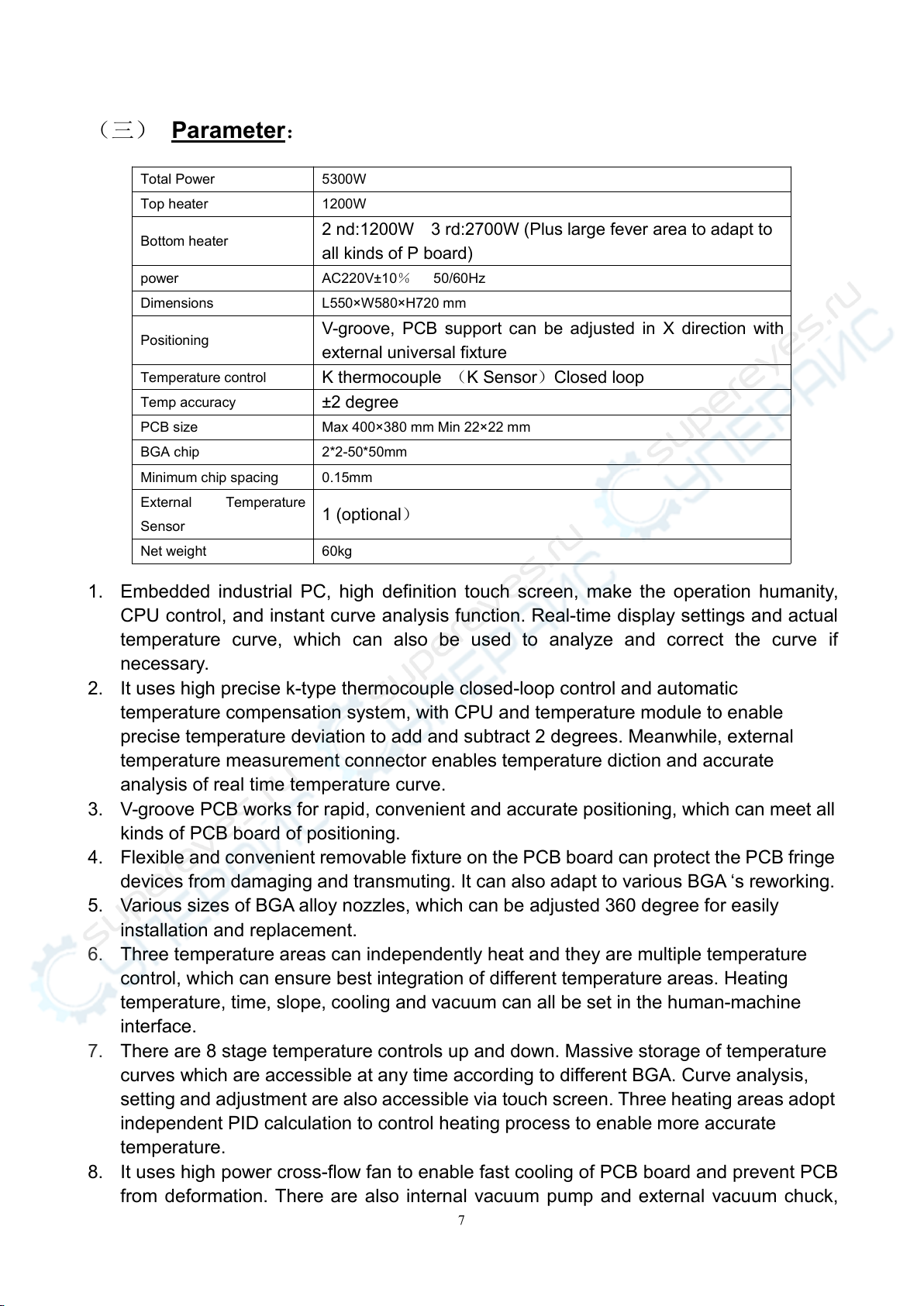
(三) Parameter:
1. Embedded industrial PC, high definition touch screen, make the operation humanity,
CPU control, and instant curve analysis function. Real-time display settings and actual
temperature curve, which can also be used to analyze and correct the curve if
necessary.
2. It uses high precise k-type thermocouple closed-loop control and automatic
temperature compensation system, with CPU and temperature module to enable
precise temperature deviation to add and subtract 2 degrees. Meanwhile, external
temperature measurement connector enables temperature diction and accurate
analysis of real time temperature curve.
3. V-groove PCB works for rapid, convenient and accurate positioning, which can meet all
kinds of PCB board of positioning.
4. Flexible and convenient removable fixture on the PCB board can protect the PCB fringe
devices from damaging and transmuting. It can also adapt to various BGA ‘s reworking.
5. Various sizes of BGA alloy nozzles, which can be adjusted 360 degree for easily
installation and replacement.
6. Three temperature areas can independently heat and they are multiple temperature
control, which can ensure best integration of different temperature areas. Heating
temperature, time, slope, cooling and vacuum can all be set in the human-machine
interface.
7. There are 8 stage temperature controls up and down. Massive storage of temperature
curves which are accessible at any time according to different BGA. Curve analysis,
setting and adjustment are also accessible via touch screen. Three heating areas adopt
independent PID calculation to control heating process to enable more accurate
temperature.
8. It uses high power cross-flow fan to enable fast cooling of PCB board and prevent PCB
from deformation. There are also internal vacuum pump and external vacuum chuck,
Total Power
5300W
Top heater
1200W
Bottom heater
2 nd:1200W 3 rd:2700W (Plus large fever area to adapt to
all kinds of P board)
power
AC220V±10%50/60Hz
Dimensions
L550×W580×H720 mm
Positioning
V-groove, PCB support can be adjusted in X direction with
external universal fixture
Temperature control
K thermocouple (K Sensor)Closed loop
Temp accuracy
±2 degree
PCB size
Max 400×380 mm Min 22×22 mm
BGA chip
2*2-50*50mm
Minimum chip spacing
0.15mm
External Temperature
Sensor
1 (optional)
Net weight
60kg
8
which can help to fetch the BGA chip;
9. Collocating with sound control "early warning" function. It can warn workers to make
some relative preparation 5-10 seconds before the completion of uninstalling or welding.
Cooling system will start after vertical wind stopped heating. When the temperature
drops to normal temperature, the cooling process will stop automatically, so that the
machine will not be aging after temperature heated up.
10. It use rocker controller for controlling the upper heater go up and down freely, and it
also has the function for zooming the picture.
CE approved, equipped with emergency stop switch and automatic power-off protection
device when emergency happens.
五、Setting:
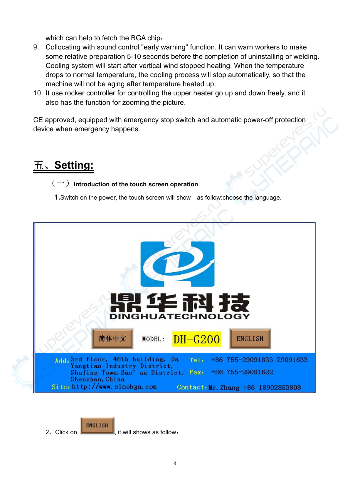
(一)Introduction of the touch screen operation
1.Switch on the power, the touch screen will show as follow:choose the language.
2、Click on , it will shows as follow:

9
3、Click the input box, it will appear as follow:
10
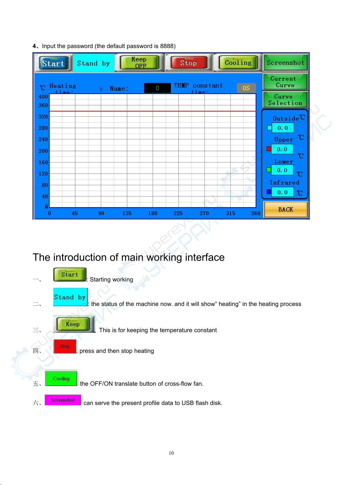
4、Input the password (the default password is 8888)
The introduction of main working interface
一、 : Starting working
二、 : the status of the machine now. and it will show” heating” in the heating process
三、 This is for keeping the temperature constant
四、 , press and then stop heating
五、 the OFF/ON translate button of cross-flow fan.
六、 can serve the present profile data to USB flash disk.
11
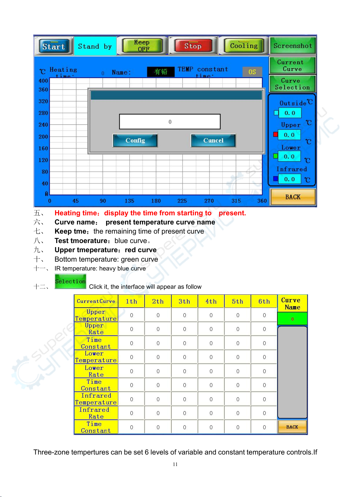
五、 Heating time:display the time from starting to present.
六、 Curve name:present temperature curve name
七、 Keep tme:the remaining time of present curve
八、 Test tmoerature:blue curve。
九、 Upper tmeperature:red curve
十、 Bottom temperature: green curve
十一、 IR temperature: heavy blue curve
十二、 Click it, the interface will appear as follow
Three-zone tempertures can be set 6 levels of variable and constant temperature controls.If
12
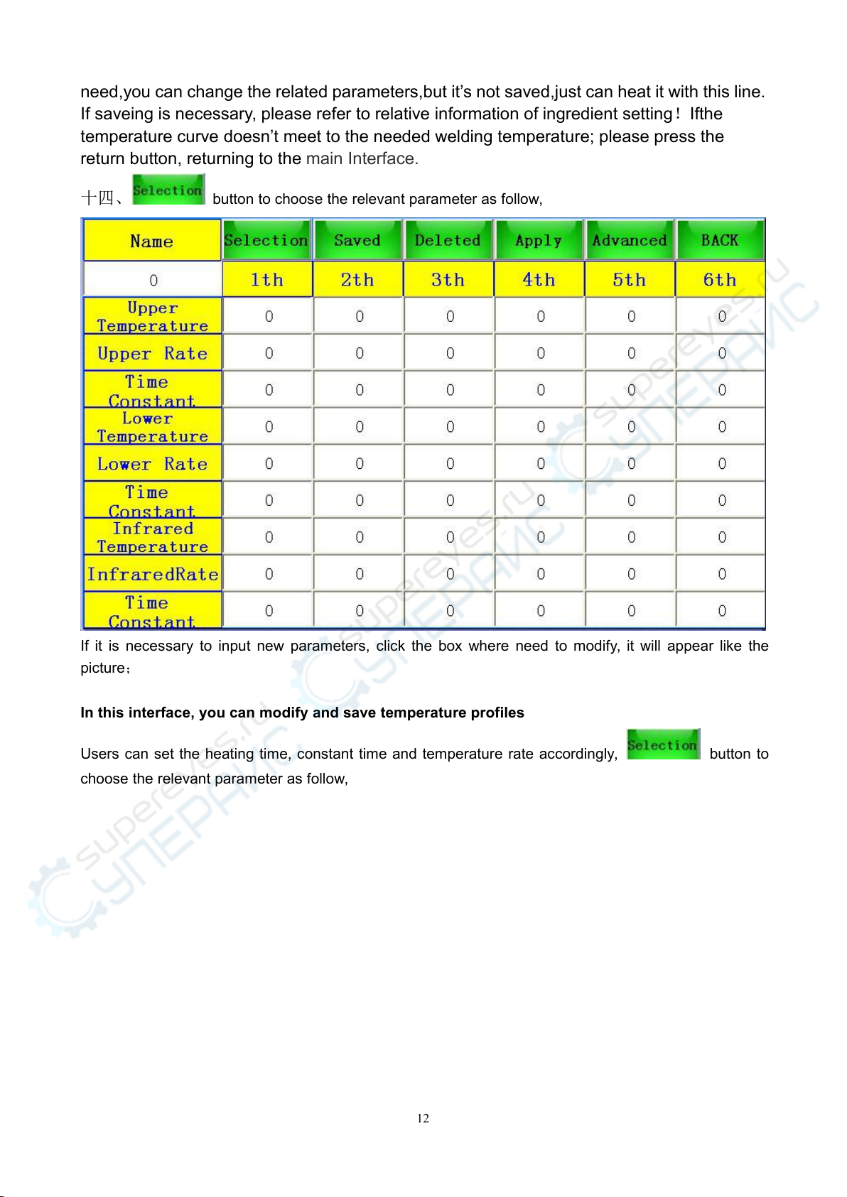
need,you can change the related parameters,but it’s not saved,just can heat it with this line.
If saveing is necessary, please refer to relative information of ingredient setting!Ifthe
temperature curve doesn’t meet to the needed welding temperature; please press the
return button, returning to the main Interface.
十四、 button to choose the relevant parameter as follow,
If it is necessary to input new parameters, click the box where need to modify, it will appear like the
picture;
In this interface, you can modify and save temperature profiles
Users can set the heating time, constant time and temperature rate accordingly, button to
choose the relevant parameter as follow,

13
If it is necessary to input new parameters, click the box where need to modify, it will appear like the
picture;
Input the parameter, press Then click after setting these three
temperature zones, then these parameters will be saved in the system with the displayed name Besides,

14
you can click the box below to change the curve’s name, the dialogue will appear as
follow
You can also click to modify the curve name
After the profile, click , the curve name and parameters displayed will be the
newest applicable data It will return to the main interface when click button

15
图8
After the profile, click , the curve name and parameters displayed will be the
newest applicable data It will return to the main interface when click button
16
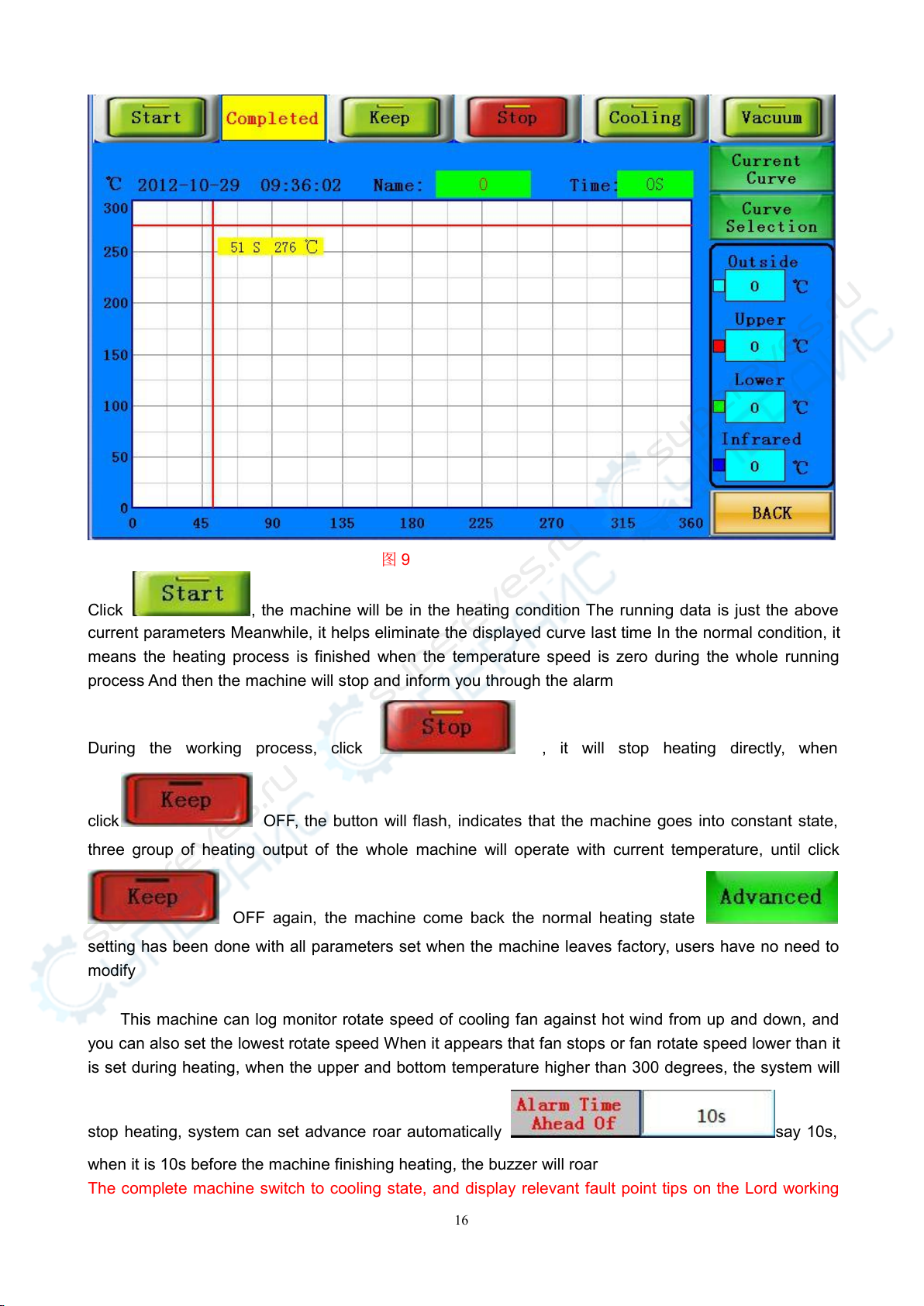
图9
Click , the machine will be in the heating condition The running data is just the above
current parameters Meanwhile, it helps eliminate the displayed curve last time In the normal condition, it
means the heating process is finished when the temperature speed is zero during the whole running
process And then the machine will stop and inform you through the alarm
During the working process, click , it will stop heating directly, when
click OFF, the button will flash, indicates that the machine goes into constant state,
three group of heating output of the whole machine will operate with current temperature, until click
OFF again, the machine come back the normal heating state
setting has been done with all parameters set when the machine leaves factory, users have no need to
modify
This machine can log monitor rotate speed of cooling fan against hot wind from up and down, and
you can also set the lowest rotate speed When it appears that fan stops or fan rotate speed lower than it
is set during heating, when the upper and bottom temperature higher than 300 degrees, the system will
stop heating, system can set advance roar automatically say 10s,
when it is 10s before the machine finishing heating, the buzzer will roar
The complete machine switch to cooling state, and display relevant fault point tips on the Lord working

17
interface, can help workers judge the fault point rapidly
When you click the following picture will appear
Attention:
When it alarm because of stoppage, all function buttons are in locked state! After managing the
stoppage and starting up, it can recover to normal state!

18
六、Operation:
This machine could apply to in soldering and desoldering the BGA chip
1. Preheating:
Preheating before reworking, the temperature of constant temperature oven is set at 80 ℃-100 ℃,
for 4-8 hours to demoist the PCBA ,to prevent the explose during reworking
2. Desoldering
1).Swith the power on , the touch screen will enter the main working interface (picture 5)click
to select the proper profile (If the profile are not suitable, you can set the profile as
mentioned above )
2).Keep the center of upper and bottom heaters in a vertical line when positioning, then fix the PCB clip
Keep the bottom of the nozzle of upper heater 2-3mm above BGA chip Click to run the
, then it will work as you settled After the process finished, raise up the Upper heater,
then take the BGA chip off with vacuum pen The procedure of desoldering is finished
图12
3.Clean-up the pad
You can clean-up the BGA pad with wick line; the best way to dismounting the tin right after the BGA
removed and the temperature difference make less damage to the pad; It can improve the activity of
soldering tin with the flux and is better to clean the soldering tin Pay attention that do not to damage the
PCB pad, and in order to ensure the reliability of BGA solder, try to use some volatile solvents when
cleaning the pad, such as plate washer water, industrial alcohol
4.BGA re-balling
Apply the paste flux evenly with the brush pen on the BGA pad, fix it on the BGA reball fixture, choose the
right stencil, and then plant tin balls properly
5.Soldering BGA balls
After setting the BGA reball station properly, put the reballed BGA chip on it, remove it after the ball is
soldered
6.Apply paste flux
Apply the paste flux with the brush pen on the PCB pad If you apply so much, it will cause connected
welding, on the contrary, it will cause null welding In order to wipe off dust and impurity of tin balls, and
enhance welding effect, the welding paste must be wiped equally
7、Place the BGA chip
Place the BGA chip on the PCB board with manual alignment and silk-screen borders,
meanwhile the tension of the solder joint when melt will have a good self- alignment effect.

19
8.Alignment
1).Turn on the laser, make sure the laser is pointed to the center of the pad for the BGA, put the BGA chip
on the PCB board
2).Select the proper profile, choose the mouting model Then click
3).The upper sucker will goes down to welding position as settled in picture 6 to pick up the
BGA chip, and goes up the Optic position settled in picture 6 ,
4).Pull the optical lens out, the BGA tin ball and welding pad will be displayed on the screen You can
check images of tin balls on the screen through the adjusting angle handle.X axis.Y axis The tin ball and
PCB welding position must be coincide completely on the screen
5).Push the CCD carmera back, the screen will appear like this. Click yes to soldering the chip
9. Soldering
1. Switch on the power, select the proper stored temp profile or set for yourself if needed.
2. Switch on the laser, put the BGA soldering pad center to the laser. Fasten the supporter. Install the
proper nozzle, 2mm-3mm larger than the BGA.
3.install the right nozzle 2mm larger than the BGA chip, click .heating as your
chosen data Cool the BGA chip after the procedure finished Raise the upper heater to make the bottom
of upper heater has 3-5mm distance from the upper surface of BGA chip, and keep cooling for 30-40
seconds Or you can move away the warm heater after the starting light off Then take away the PCB
board from the supporter
(1) Null welding:
Because of counterpoint by hand will cause deviation between chip and welding plate, surface tension of
tin ball will have a process of automatic correction between BGA chip and welding pad Once heating,
BGA falls not evenly, which will cause that the chip drops not evenly It will cause the phenomenon of
missing weld and false weld if stop reflowing at this time, the chip will not fall normally So it is necessary
for you to extend heating time of third .forth temperature zones or add the bottom pre-heating
temperature to make the tin balls meltdown and drop evenly
(2) short-circuiting:
When the ball reached the melting point, it is in a liquid state , if too long or too high temperature and
pressure, it will destroy surface tension of solder balls and the supporting role, resulting in short-circuit
phenomenon when reflows, the chips fall entirely on the PCB pads the , so we need to appropriately

20
reduce the heating section of the third and fourth soldering temperature and time , or reduce the bottom
of the preheat temperature
Attention: It will cause occur odor in the normal working process In order to assure safe and healthy
operation environment, please keep ventilation in and out of the room
七 、 Outer temperature measurement
couple usage
(A)the function of external temperature sensor
a To measure actual temperature more accurately during the welding process
b Because it can move freely, it is more convenient to measure different parts of ready to be measured
component
c It has correct function, which can make the temperature of welding parts is more familiar with the
setting temperature
(B)The installation of couple
a Check that whether the couple line is in good condition
b Put the plug of couple line in the socket of external couple
c After right installation of couple, the touch screen will show the current temperature of couple
(C)Use the couple to measure actual temperature
a Put the PCB board on the BGA Rework station Use tinfoil paper to fix the couple line on the PCB board
b Adjust the detector and make it 1-2mm higher than the ready to be measured parts
c Adjust the position of PCB board so that the ready to be heated parts is under the
upper warm wind nozzle (Like picture sixteen)
d Adjust the adjusting knob of head blow-dryer up and down so that the upper warm wind nozzle is
2-3mm higher than the surface of PCB board
e Choose the touch screen interface (like picture five), click “start”, then the upper heater begin to heat
f Now the screen will show red. light blue.green three curves (Picture seventeen)
The temperature curve of external couple (light blue)
The current temperature curve of internal couple of upper heater (red)
The current temperature curve of internal couple of bottom heater (green)
Table of contents
Other Dinghua Rework Station manuals


