Metcal HCT-1000 User manual

7000-2931_B
HCT-1000
HCT-1000
User Guide
HCT-1000
Betriebsanleitung
HCT-1000
Manuel d’utilisation
HCT-1000
Manuale dell'utente
HCT-1000
Guía del usuario
www.metcal.com

1
INTRODUCTION
The HCT-1000 is a hand-held convection rework tool. It features digital controls, multiple
modes of operation, internal or external feedback control and integrated vacuum pick-up
for component placement and removal. Additionally, this unit may be connected to the
PCT-1000 as part of the Modular Rework System.
CONTENTS
1. Safety & Warranty 1
2. Specifications 2
3. Unit identification 3
4. Setup and unit operation 4
5. Additional Features 7
6. Nozzle Information 8
7. Operation 8
8. Troubleshooting 9
9. Maintenance 9
SAFETY
Intended Use:
WARNING: Use of this equipment in ways other than those described in this User Guide
may result in injury to persons or damage to property. Use this equipment only as
described in this User Guide.
OK International cannot be responsible for injuries or damages resulting from unintended
applications of its equipment. Unintended uses may result from taking the following
actions:
• Making changes to equipment that has not been recommended in the User Guide
• Using incompatible or damaged replacement parts
• Using unapproved accessories or auxiliary equipment
Safety Precautions:
• Do not operate this unit in excess of maximum ratings/settings
• Always wear appropriate personal protective clothing or apparel
• This equipment is for indoor use only
Warranty
OK International warrants the HCT-1000 hand-held convection rework tool power supply
against any defects in materials or workmanship for one (1) year from the date of
purchase by the original owner.
OK International warrants the HCT-1000 hand-held convection rework tool hand-piece
(HCT-HV1) against any defects in materials or workmanship for one (1) year from the
date of purchase by the original owner.
OK International warrants the HCT-1000 heater assembly (HCT-HTRASSY) against any
defects in materials or workmanship for ninety (90) days from the date of purchase by
the original owner.
This Warranty excludes normal maintenance and shall not apply to any opened,
misused, abused, altered or damaged items. If the product should become defective
within the warranty period, OK International will repair or replace it free of charge at its
sole option. The replacement item(s) will be shipped, freight prepaid, to the original
purchaser. The warranty period will start from the date of purchase. If the date of
purchase cannot be substantiated the date of manufacture will be used as the start of
the warranty period

2
2. HCT-1000 SPECIFICATIONS
Size
9” x 7” x 6” (229 mm x 178 mm x 152 mm)
Weight
12lbs (5.44 Kg)
Input Voltage
100-240 VAC, 50/60 Hz
Rated Power
600W
Pollution Degree Category
II
Storage Temperature
-10°C to 60°C (14°F to 140°F)
Operating Temperature
0°C to 50°C (32°F to 122°F)
Air Pump Type
Diaphragm
Air Flow
5-25 l/min
Vacuum Pump
15” Hg (381 mm Hg)
Control Temperature
450°C
Surface Resistivity
107Ωto 1011Ω
Noise Level
< 55 dB
Certifications
TUV, CE
Max. Relative Humidity
80% for temperature up to 31°C (87.8°F) Decreasing
linearly to 50% relative humidity at 40°C (104°F)
System Modes
HCT, MRS
Operational Modes
Setup, Run, Manual, Active Setup
Memory Locations
50
Display
LCD 20 X 4 display segments
System Includes
Description
HCT-PS1000
HCT-1000 Power Supply
HCT-HV1
Hand-piece with integral vacuum, cord and connector
HCTA-TH1
Hand-piece tool Holder
HNA-1
Nozzle Adapter
HCTA-NW1
Nozzle Wrench
HCTA-VC-KIT
Vacuum Cup Kit (4), 3/16", 1/4", 5/16", 7/16"
AC-TCK-36-36
Thermocouple, 36 AWG
HCTA-CC
Communications Cable, 4’
HN-J0005
Nozzle 5mm Diameter
Accessories
HCTA-VC24
Vacuum Cup, 3/32” (2.38mm)
HCTA-VC50
Vacuum Cup, 3/16” (5.00mm)
HCTA-VC64
Vacuum Cup, ¼” (6.4mm)
HCTA-VC80
Vacuum Cup, 5/16” (8mm)
HCTA-VC11
Vacuum Cup, 7/16” (11mm)
AC-TCK-40-36
Thermocouple, 40 AWG
HCT-HTRASSY
Heater Assembly
HCT-FS2
Footswitch, Dual, HCT-1000
HCT-NC
Nozzle Carrier, HCT-1000 nozzles

3
3. Unit Identification
Figure 1 HCT-PS1000 Power Supply
Figure 3: Run Mode, Before Profile Start
Figure 4: Run Mode, After Profile Start, MRS Mode
Z
1
:
1
5
0
°c
6
5
s
P
0
6
Z
2
:
2
0
0
°c
5
5
s
T
C
:
I
N
T
Z
3
:
2
5
0
°c
4
5
s
Z
4
:
3
0
0
°c
3
0
s
Z
1
:
5
5
s
P
0
6
T
-
S
E
T
:
1
5
0
°c
T
C
:
I
N
T
T
-
H
t
r
:
1
3
6
°c
1
2
5
°c
R
E
M
O
V
E
(↵)Enter/Profile Select
Power On/Off
Timer/Temperature Adjust Down
⊕Timer/Temperature Adjust Up
and Profile start/abort
Thermocouple (TC1)
Thermocouple (TC2)
Hand-piece Connector
Power Connector
Footswitch Connector
Communications Connector
Figure 2
Back Panel Detail
TC 1:
Active Zone
Zone Set Point
Actual Heater Reading
Temperature Monitor
Thermocouple
Control
Selected Profile
Place/Remove Option
(Only Available in MRS Mode)
Zone Target Temperature
Profile Parameters

4
Figure 5 HCT-HV1 Hand-piece Assembly
4. Setup and unit operation
1. Basic unit setup
1. Connect the hand-piece assembly, HCT-HV1, to the power supply.
2. Plug the power cord into the power connector (Figure 2). Plug the power cord
into a grounded wall socket of the rated input line voltage.
3. Turn On the unit by pressing the Power button momentarily.
4. To Abort a Profile (to the Cool-Down zone*) press and hold the (red) on the
footswitch or (red) on the hand-piece down while in Run Mode.
5. Once the cool zone is finished, turn off the unit by pressing the Power button
momentarily. Note ~ you must be out of set-up mode in order to do this. I.e.
no flashing numbers on the display.
2. System Mode Selection
The HCT-1000 has two system modes of operation.
•The first mode is HCT. In this mode, the HCT-1000 is used as a standalone
handheld convection rework tool.
•The second mode is MRS. In this mode, the HCT-1000 is used as part of a
Modular Rework System. The unit is connected via cable to a PCT-1000 and
may be used with the ATH-1100A Adjustable Tool Holder. In this mode the
HCT-1000 provides timing control for both units and the ATH-1100A allows
repeatable place and remove operations.
•Plug the Communications Cable into the Communication Connector (Figure 2
above) on the HCT-1000 and the PCT-1000. When connected in MRS mode
the time setting on the PCT-1000 will display “- -“.
•Selection of the System mode is made in Setup mode, refer to section 3.1.
Additional operational options are available, refer to section 3.5.
3. Operational Mode Selection
Vacuum Pick-up Tube
ê(red) Profile Start/Abort
é(blue) Vacuum Activation
Vacuum Pick-up Tube
Adjustment
Heater Assembly
Figure 6 HCTA-TH1
Figure 7

5
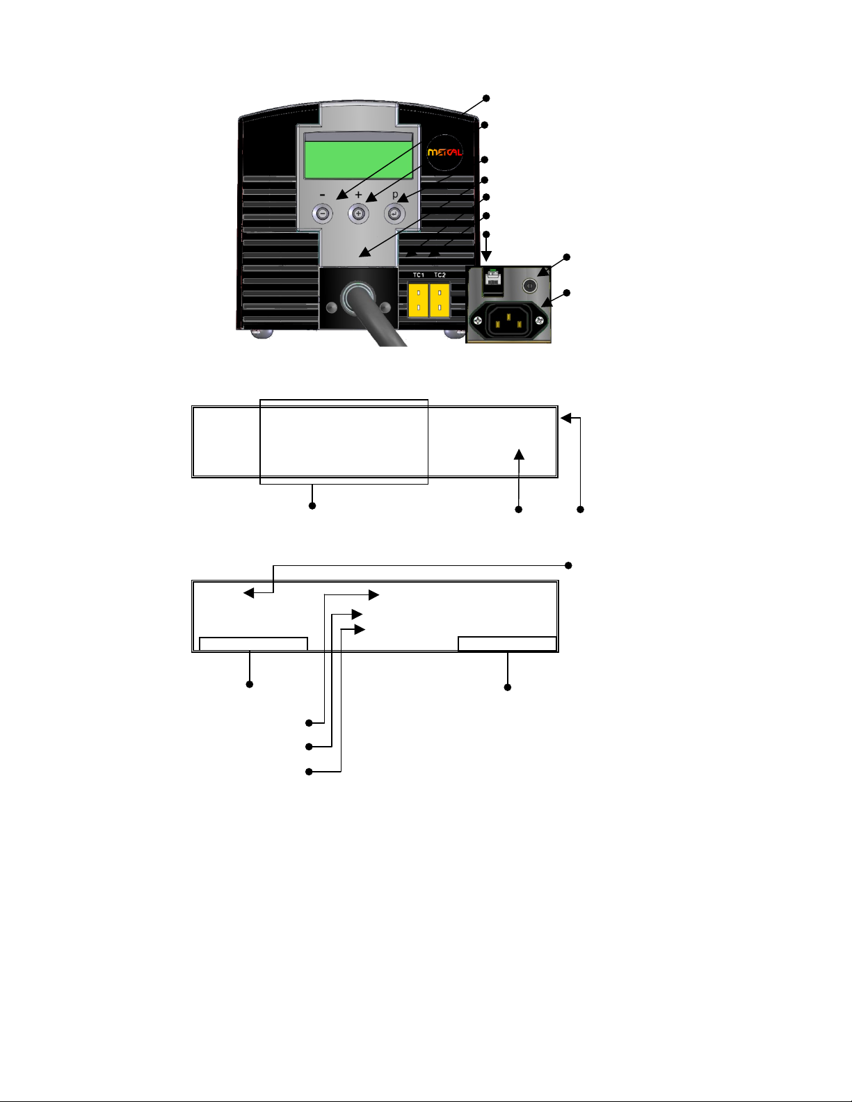
The HCT-1000 has four operational modes. The operational modes are Setup, Run,
Manual and Active Setup. The Setup mode is for modifying system or profile
parameters. The Run mode is for operating the unit with a profile that uses four
zones of heating. The Manual mode is for operating the unit with a single zone of
heat and no time limit. The Active Setup mode allows for the changing of
parameters within a running profile.
1. Setup Mode
1. Press the Mode button (↵)once to start “P:” flashing
2. Use the ⊕/ buttons to scroll through the profiles
3. Press (↵)to select the desired profile
4. Press and hold (↵) for 3 seconds to activate program mode (first
temperature in zone 1 will flash).
5. Run Mode setup; proceed to step 3.1.6.1; Manual Mode setup
proceed to step 3.1.7.1.
6. Run Mode Setup
1. Use the ⊕/ buttons to change the temperature to the desired
value. (Note: continually pressing either the ⊕or buttons for
5 seconds will change the count up/down in an accelerated
mode)
2. When the value is set, press (↵)to move to the next parameter.
3. Repeat steps 3.1.6.1 & 3.1.6.2 until profile is programmed.
Note: In the Cool-Down Zone you can only modify the Time
parameter
4. Proceed to step 3.1.8.
7. Manual Mode Setup
1. Use the ⊕/ buttons to change the temperature to the
desired value. (Note: continually pressing either the ⊕or
buttons for 5 seconds will change the count up/down in an
accelerated mode)
2. Set the Time for Zone 1 to a value greater than 300 seconds.
The display will now show the word MANUAL and Z2, Z3, Z4
will no longer be shown on the display.
Note: Manual mode profiles do not have a time requirement and
once activated will run until the profile is stopped. . However,
during the cool zone, the profile can be restarted at any time by
pressing ⊕(or the red button on the footswitch or handpiece)
8. Press (↵)to move to the next parameter. This is the HCT or MRS
option. Use ⊕or to switch between HCT or MRS or press (↵)to
skip
9. Press (↵)to move to the next parameter. This is the Internal or
External TC option. Use ⊕or to switch between Int or TC1 or press
(↵)to skip.
Note: When TC1 is selected, TC1 becomes the master thermocouple
and provides feedback to the power supply.
10. Press (↵)to move to the next parameter. This is the Airflow option
(AF). Use ⊕to increase or to decrease the airflow. The range is
adjustable from 1-10. Note: The Air Pump will turn on while adjusting
the Airflow. Press (↵)to skip.
11. Press (↵)to move to the next parameter. This is the Security Lockout
function. HCT-1000 systems are supplied with a lockout feature to
prevent operators from editing profiles etc. To activate this function, a 4
digit number must be entered within a program setup as explained
below.If the pass code is set at 0000 the programs are not protected.
1. When C: 0000 appears on the screen, you can select a 4 digit pass
code.

6
2. When the first digit flashes, use the or ⊕buttons to select the
preferred number.
3. Press (↵) and repeat step 2for all digits.
4. Press-and-hold (↵)to quit code entry.
5. From this point on you can only edit profiles after entering the
correct code
Security Lockout Notes:
•You can ‘turn off’ the pass-code protection by 1st going into Program
mode, entering the current code then setting the new code to ‘0000’
–All users now have full access to all program functions.
•One code protects all profiles, not individual profiles.
•If the Pass-code is lost or forgotten then the Master Reset function
will restore the factory defaults including erasing the pass-code
Master Reset.
To reset the unit it to factory settings, the following procedure can be used.
•Press and hold ⊕and (↵)
•Whilst keeping ⊕and (↵) depressed, switch the unit on
using
PLEASE NOTE: Use of the master reset will erase all stored programs.
12. Once required changes have been made, press and hold (↵)for 3
seconds until the LCD stops flashing, to set the profile to memory and
exit setup mode. This operation can be actioned at any step while in
Setup Mode.
2. Run & Manual Mode
1. Turn on the unit by pressing the Power button.
2. HCT start-up message and Software Rev # are momentarily displayed
before displaying last-used profile settings. Note: The unit may display
MRS if that was the last operational state.
3. IMPORTANT ~ If “TC: TC1” is displayed on the panel (see Figure 4
above) ensure that the external thermocouple is suitably positioned in the
heat path. Neglecting to do this could result in premature heater failure
and possible heat damage to items in the heater path.
4. Select the desired profile.
5. When the chosen profile is shown, press (↵)to select the desired profile
6. To start the profile, depress the (red) on the footswitch or (red) on
the hand-piece once
7. As the profile runs you will see the current zone, time remaining, heater
value and temperature set point. Manual mode profiles will display
“Manual” and will not display time remaining.
8. To quit the profile, simply depress the (red) on the footswitch or
(red) on the hand-piece. The profile will skip to the Cool-Down Zone.
During the cool zone, the profile can be restarted at any time by pressing
a red button on the footswitch or handpiece.
3. Active Setup Mode
1. Select Profile to be modified as per steps 1 3 above
2. To activate Active Setup Mode press (↵)for 3 seconds then depress the
(red) on the footswitch or (red) button on the hand-piece once the
temperature in Z1 has started to flash
3. Profile will start to run and ‘SETUP’ will be displayed on LCD
4. To modify the current zone set-temperature use the ⊕/ buttons
5. To increase the time of the current zone press and hold the (↵)button as
the zone ends. Instead of stepping onto the next zone the current zone

7
time-setting will increment the original setting for as long as you keep the
(↵)button depressed. Releasing the button will allow the profile to
progress onto the next Zone.*
6. To decrease the zone time, depress the (red) on the footswitch or
(red) button on the hand-piece at the desired time. This will set the time
to memory and advance the profile into the next zone.** Note: Steps
3.4.5 & 3.4.6 can be carried out simultaneously
7. Once required changes have been made, allow the profile to finish. Press
and hold (↵), until the LCD tops flashing, to set the profile to memory and
exit setup mode
8. *Note: feature not available in Cool-Down Zone
9. **Note: This feature is NOTavailable in the Cool-Down Zone. Pressing a
red button on the footswitch or handpiece will return you to Zone 1 again.
If Cool Zone time adjustments are required they must be made in Run
Mode Setup (step 3.1.5)
5. Additional Features
1. Integrated Vacuum Pick-up
The vacuum pick-up tube has 1.0” (25.4 mm) of travel and is spring loaded
to prevent damage to components during attachment.
Use an appropriate sized vacuum cup to make a seal on the component.
2. HCT System Mode
1. Press the (blue) on the footswitch or on the hand-piece once to
activate the vacuum pump and again to deactivate.
3. MRS System Mode –Place or Remove selection
1. To toggle between Place and Remove; press and hold the
(blue) on the footswitch or on the hand-piece for 3 seconds.
4. MRS System Mode -Place
1. Press the (blue) on the footswitch or on the hand-piece once to
activate the vacuum pump and again to deactivate.
5. MRS System Mode -Remove
1. The integrated vacuum pick-up will automatically activate the
vacuum and retract the vacuum pick-up tube at the completion of
Zone 4 (Z4) in Run mode. The vacuum will be active for the
duration of the ZC (Cool-Down Zone).
6. MRS System Mode –Positive Vacuum Indicator
1. VAC will be displayed when the vacuum has been activated while
in Setup or Run Mode (Figure 4). VAC will blink when a positive
seal has been achieved with the component.
7. External Thermocouple Control
1. When using the HCT-1000 with the external thermocouple (TC1
see Figure 4 above), TC1 is used to provide external feedback
control. Ensure that the thermocouple is placed in the heat path.
Failure to do so may result in an error or damage to the
component. TC2 can be used for temperature monitoring (refer to
1.5.7)
2. When using the HCT-1000 with external thermocouples in MRS
mode, TC1 on the HCT-1000 becomes the master thermocouple
and is used to provide external feedback for the entire system.
TC2 on the HCT-1000 and TC1 & TC2 on the PCT-1000 can be
used for temperature monitoring only (refer to 1.9).

8
8. Temperature Monitoring
1. While using the HCT-1000 with the internal thermocouple (INT
see Figure. 3 above), TC1 and TC2, the external thermocouples,
may be used to monitor temperature.
2. Attach a thermocouple to TC1 and/or TC2 and attach to the area
to be monitored. When attached, the appropriate thermocouple
will be displayed (see Figure 4 above).
9. TC1 Input calibration.
1. TC1 Input calibration is possible using the following procedure.
•Connect a calibrated temperature input control box to TC1
•Run a complete profile to ensure the units internal temperatures are
stable.
•To enter calibration mode, press and hold the and (↵)buttons for
five seconds.
•This will enter you into a calibration mode.
•Adjust temperature to suit external calibration box using + and –
buttons.
•Press (↵) to return to normal run mode.
6. Nozzle Attachment
1. Secure the Nozzle Adapter (HNA-1) to Heater
Assembly
1. Loosen clamp screw counterclockwise (Figure
6, 1)
2. Close the clamp (Figure 6, 2).
3. Slide the Nozzle Adapter up the heater
assembly (Figure 5) until it stops.
4. Tighten the clamp screw clockwise (Figure 6,
1) for firm fit of the adapter to the heater
assembly. Once adjusted, removing the
adapter is done by opening the clamp and
sliding the adapter off the heater assembly.
2. Nozzle to Nozzle Adapter
1. Select the proper nozzle for the application.
2. To attach; screw the nozzle to the nozzle adapter (Figure 6, 3); tighten
clockwise with Nozzle Wrench.
3. To remove; unscrew the nozzle from the adapter (Figure 6, 3); loosen
counterclockwise with Nozzle Wrench.
3. Nozzle Selection
1. Select the appropriate sized nozzle for the application. This is only a
sample of the available nozzles. Please refer to the HCT-1000 Nozzle
Selection Guide or visit our website www.metcal.com for the complete
selection.
7. Operation
1. De-Soldering Components using convection heat
1. Select the proper nozzle, and secure it to the adapter.
Figure 8: Nozzle Adapter
(HNA-1)
1
2
3
HN-J0005,
5.0MM
HN-B1010
10MM x 10MM
HN-1818
18MM x 18MM
HN-B4040,
40MM x 40MM

9
2. Set the desired profile.
3. Move the nozzle close to the component leads; maintain 3-5 mm
distance. Use the hot air to melt the solder
4. When solder is molten, use the integrated vacuum, tweezers or other
suitable tool to remove the component from the circuit board
2. Soldering Components using convection heat
1. Choose the proper nozzle, secure it to the adapter.
2. Apply the right amount of solder to the circuit board; position the
component on the circuit board.
3. Set the desired profile.
4. Move the nozzle closer to the component leads, blow hot air onto the
leads and melt the solder.
8. Troubleshooting
1. Unit does not power ON
•Check the power cord
•Check to see that you have mains voltage
2. OH displayed on the LED screen
•Unit has exceeded the internal safety cut-off
•Allow unit to cool
•Check placement of thermocouple (if used)
•Reset the unit by cycling the power
3. TCFAULT displayed on LED screen
•Check location of thermocouple
•Ensure the thermocouple is firmly inserted into the correct TC
connector
•Replace thermocouple if problem persists
4. Flashing zone and temperature parameters while in Run Mode
•Indicates the unit cannot meet the programmed time and
temperature as set
9. Maintenance
The Hand-piece (HCT-HV1) will be part of OK International’s Service Exchange Program
or the heater assembly (HCT-HTRASSY) can be purchased separately as a replacement
part.
Please visit OK International’s web page (www.metcal.com) where you will find
additional information on systems, accessories, technical notes, and more.

10
EINFÜHRUNG
Das Heißluftsystem HCT-1000 ist ein tragbares Reworksystem. Es hat eine Digitalanzeige,
mehrere Betriebsmodi, interne oder externe Rückkopplungssteuerung und integrierte
Vakuumaufnahme zurEntfernung und Platzierung. Des Weiteren kann dieses System mit der
PCT-1000 verbunden werden und wird so zu einem modularen Reworksystem.
INHALT
1. Sicherheit und Garantie 10
2. Technische Daten 11
3. Beschreibung der Symbole 12
4. Setup und Inbetriebnahme 13
5. Weitere Leistungsmerkmale 17
6. Montage der Düse 18
7. Betrieb 19
8. Problembehebung 19
9. Instandhaltung 19
SICHERHEIT
Verwendungszweck:
WARNUNG: Wenn das Gerät anders verwendet wird, als in dieser Betriebsanleitung
beschrieben, besteht die Gefahr von Personen- und Sachschäden. Verwenden Sie
dieses Gerät nur im Einklang mit der Beschreibung in dieser Betriebsanleitung.
OK International haftet nicht für Verletzungen oder Schäden, die aufgrund einer
zweckfremden Verwendung dieses Gerätes entstehen. Eine zweckfremde Verwendung
schließt auch Folgendes ein:
• Veränderungen am Gerät, die in der Betriebsanleitung nicht empfohlen werden
• Verwendung von nicht kompatiblen oder beschädigten Ersatzteilen
• Verwendung von nicht zugelassenen Zubehörteilen oder Hilfsgeräten
Vorsichtsmaßnahmen:
• Dieses Gerät darf nicht außerhalb der maximalen Nennwerte/Einstellungen betrieben
werden
• Immer geeignete Schutzkleidung tragen
• Dieses Gerät ist nur zur Verwendung in Gebäuden bestimmt
Garantie
OK International gewährt für das Netzteil des tragbaren HCT-1000-Konvektions-Reworksystems
hinsichtlich Material-oder Verarbeitungsmängel eine Garantie von einem (1) Jahr, gerechnet ab
Datum des Kaufs durch den ursprünglichen Eigentümer.
OK International gewährt für den Lötgriffel (HCT-HV1) des tragbaren HCT-1000-Konvektions-
Reworksystems hinsichtlich Material-oder Verarbeitungsmängel eine Garantie von einem (1) Jahr,
gerechnet ab Datum des Kaufs durch den ursprünglichen Eigentümer.
OK International gewährt für das Heizelement (HCT-HTRASSY) des HCT-1000
hinsichtlich Material-oder Verarbeitungsmängel eine Garantie von neunzig (90) Tagen,
gerechnet ab Datum des Kaufs durch den ursprünglichen Eigentümer.
Diese Garantie schließt die normale Wartung aus und gilt nicht für geöffnete,
unsachgemäß oder zweckentfremdet verwendete, modifizierte oder beschädigte Geräte.
Wenn innerhalb des Garantiezeitraums Mängel am Produkt auftreten, repariert oder ersetzt
OK International es kostenlos nach eigenem Ermessen. Reparierte bzw. ausgetauschte
Teile werden an den Originalkäufer geliefert, die Versandkosten trägt OK International. Der
Garantiezeitraum beginnt ab Zeitpunkt des Kaufs. Wenn das Kaufdatum nicht
nachgewiesen werden kann, gilt das Herstellungsdatum als Beginn des Garantiezeitraums.

11
2. TECHNISCHE DATEN ZUM HCT-1000
Maße
229 x 178 x 152 mm
Gewicht
5,44 kg
Eingangsspannung
100 V AC, 50/60 Hz
Nennleistung
600 W
Verschmutzungsgrad-
Kategorie
II
Temperaturbereich für die
Aufbewahrung
-10 °C bis 60 °C
Umgebungstemperatur bei
Betrieb
0 °C bis 50 °C
Luftpumpe
Membran
Luftstrom
5 –25 l/min
Vakuumpumpe
381 mm Hg
Einstellbare max. Temperatur
450°C
Spezifischer
Oberflächenwiderstand
107Ωbis 1011Ω
Geräuschpegel
< 55 dB
Zulassungen
TUV, CE
Max. relative Luftfeuchtigkeit
80 % bei Temperaturen bis zu 31 °C mit linearer Reduzierung
der relativen Luftfeuchtigkeit bis zu 50 % bei 40 °C
Systemmodi
HCT -Heißluftsystem, MRS -Reworksystem
Betriebsarten
Setup, Betrieb, Manuell, Aktives Setup
Speicherplätze
50
Betriebsartanzeige
LCD, 20 x 4 Anzeigesegmente
System beinhaltet
Beschreibung
HCT-PS1000
Netzteil HCT-1000
HCT-HV1
Lötgriffel mit eingebautem Vakuumrohr, Kabel und
Stecker
HCTA-TH1
Halter für Lötgriffel
HNA-1
Adapter für Düsen
HCTA-NW1
Montageschlüssel für Düsen
HCTA-VC-KIT
Saugnapfkit, 4 x –Ø 5 / 6,4 / 8 /11 mm
AC-TCK-36-36
Thermofühler ( AWG 36)
HCTA-CC
Anschlusskabel PCT-/HCT-1000, 1,2 mtr.
HN-J0005
Heißluftdüse Ø 5 mm
Zubehör
HCTA-VC24
Saugnapf, Ø2,38 mm
HCTA-VC50
Saugnapf, Ø5,00 mm
HCTA-VC64
Saugnapf, Ø6,4 mm
HCTA-VC80
Saugnapf, Ø8 mm
HCTA-VC11
Saugnapf, Ø11 mm
AC-TCK-40-36
Thermofühler (AWG 40)
HCT-HTRASSY
Heizelement für Lötgriffel
HCT-FS2
Dual-Fußschalter für HCT-1000
HCT-NC
Ablageständer für HCT-1000 Düsen

12
3. Beschreibung der Symbole
Abb. 1: Netzteil HCT-PS1000
Abbildung 3: Betriebsmodus, vor Profilstart
Abbildung 4: Betriebsmodus, nach Profilstart, MRS-Modus
Z
1
:
1
5
0
°c
6
5
s
P
0
6
Z
2
:
2
0
0
°c
5
5
s
T
C
:
I
N
T
Z
3
:
2
5
0
°c
4
5
s
Z
4
:
3
0
0
°c
3
0
s
Z
1
:
5
5
s
P
0
6
T
-
S
E
T
:
1
5
0
°c
T
C
:
I
N
T
T
-
H
t
r
:
1
3
6
°c
1
2
5
°c
R
E
M
O
V
E
TC 1:
Zonenvorgab
e
Tatsächlicher
Heizmesswert
Temperaturanzeige
Ausgewähltes
Profil
Zonenzieltemperatur
Profilparameter
Netzschalter (Ein/Aus)
Reduzierung der Zeit und Temperatur
(↵) Eingabe/Profilauswahl
⊕Erhöhung der Zeit und Temperatur
Profil starten/abbrechen
Thermofühler (TC1)
Thermofühler (TC2)
Buchse für Lötgriffel
Buchse für
Netzkabel
Fußschalter
Anschlüsse
Abb. 2: Rückseite
Aktive Zone
Steuerung für Thermofühler
Profilparameter
Option Platzieren/Entfernen
(Nur im MRS-Modus verfügbar)

13
Abb. 5: Lötgriffel HCT-HV1
4. Setup und Inbetriebnahme
1. Grundlegende Geräteeinrichtung
1 Schließen Sie den Lötgriffel HCT-HV1 an das Netzteil an.
2 Stecken Sie das Netzkabel in die Buchse (Abb. 2). Stecken Sie das Netzkabel
in eine Schukosteckdose mit der in der Spezifikation angegebenen
Netzspannung.
3 Schalten Sie das Gerät durch kurzes Drücken des Netzschalters ein.
4 Zum Abbrechen eines laufenden Profils (sofortiger Wechsel in die
Abkühlphase*) drücken Sie die rote Taste (ê)am Fußschalter oder (ê)am
Lötgriffel.
5 Nach Ablauf der Abkühlphase kann das System abgeschaltet werden. Dazu
drücken Sie kurz auf den Netzschalter .Hinweis: Zum Abschalten darf
sich das System nicht im Setup-Modus befinden, d. h. auf der Anzeige dürfen
keine blinkenden Zahlen vorhanden sein.
2. Auswahl des Systemmodus
Das HCT-1000 verfügt über zwei Systembetriebsmodi.
•Der erste Betriebsmodus ist „HCT“. In diesem Modus wird das HCT-1000 als
unabhängiges handbetriebenes Konvektions-Reworksystem eingesetzt.
•Der zweite Betriebsmodus ist „MRS“. In diesem Modus wird das HCT-1000
als Teil eines modularen Reworksystems (Modular Rework System, MRS)
eingesetzt. Das System wird über ein Anschlusskabel mit der PCT-1000
verbunden und kann mit demverstellbaren Ablageständer für den Lötgriffel
ATH-1100A verwendet werden. In diesem Modus steuert das HCT-1000
Vakuumrohr
ê(rot) Profilstart/-abbruch
é(blau) Aktivierung des
Vakuums
Einstellung für das
Vakuumrohr
Heizelement
Abb. 7
Abb: 6 - HCTA-TH1

14
beide Systeme. In Verbindung mit dem Ablageständer ATH-1100A erlaubt
dies wiederholbare Vorgänge zum Platzieren und Entfernen.
•Stecken Sie das Übertragungskabel in die dafür vorgesehene Buchse (Abb. 2)
am HCT-1000 und der PCT-1000. Ist der MRS-Modus eingestellt, wird auf der
Zeitanzeige bei der PCT-1000 „- -“ angezeigt.
•Die Auswahl des Systemmodus (HCT/MRS) erfolgt im Setupmodus (siehe
Abschnitt 3.1). Weitere Betriebsoptionen sind verfügbar (siehe Abschnitt 3.5).
3. Auswahl des Systemmodus
Das HCT-1000 verfügt über vier Betriebsmodi. Die Betriebsmodi lauten Setup,
Betrieb, Manuell und Aktives Setup.Der Modus „Setup“ ermöglicht das Modifizieren
von System-oder Profilparametern. Der Modus „Betrieb“ ermöglicht den Betrieb
des Geräts mit einem Profil, das vier Heizzonen verwendet. Der manuelle Modus
ermöglicht den Betrieb des Geräts mit einer einzelnen Heizzone ohne Zeitlimit. Der
Modus „Aktives Setup“ ermöglicht das Modifizieren von Parametern bei einem
laufenden Profil.
1. Modus „Setup“
1. Drücken Sie einmal die Eingabetaste (↵), worauf „P:“ im Display zu
blinken beginnt.
2. Verwenden Sie die Tasten ⊕/ , um durch die Profile zu blättern.
3. Drücken Sie (↵), um das gewünschte Profil auszuwählen.
4. Halten Sie die Eingabetaste (↵) 3 Sekunden lang gedrückt, um den
Programmmodus zu aktivieren (die erste Temperaturanzeige in Zone 1
beginnt zu blinken).
5. Einrichten des Modus „Betrieb“, weiter mit Schritt 3.1.6.1;
Einrichten des Modus „Manuell“, weiter mit Schritt 3.1.7.1.
6. Einrichten des Modus „Betrieb“
1. Verwenden Sie die Tasten ⊕/ , um den gewünschten
Temperaturwert einzustellen. Hinweis: Werden die Tasten ⊕
oder 5 Sekunde lange gedrückt, wird eine beschleunigte
Erhöhung bzw. Reduzierung des angezeigten Wertes bewirkt.
2. Nachdem der Wert eingestellt wurde, drücken Sie (↵), um zum
nächsten Parameter zu gelangen.
3. Wiederholen Sie die Schritte 3.1.6.1 und 3.1.6.2, bis das Profil
programmiert ist. Hinweis: In der Abkühlzone kann nur der
Zeitparameter geändert werden.
4. Weiter mit Schritt 3.1.8.
7. Einrichten des Modus „Manuell“
1. Verwenden Sie die Tasten ⊕/ , um den benötigten Wert für
die Temperatur einzustellen. (Hinweis: Durch 5 Sekunden
langes Gedrückthalten der Taste ⊕oder wird eine
beschleunigte Erhöhung bzw. Reduzierung des angezeigten
Wertes bewirkt.)
2. Stellen Sie die Zeit für Zone 1 auf einen Wert von mehr als 300
Sekunden ein. Auf der Anzeige wird nun das Wort MANUAL
eingeblendet, und Z2, Z3, Z4 sind nicht mehr zu sehen.
Hinweis: Profile im manuellen Modus haben kein Zeitlimit und
laufen nach der Aktivierung so lange, bis sie gestoppt werden.
In der Abkühlzone kann das Profil zu jeder Zeit wieder neu
gestartet werden. Drücken Sie dazu die Taste ⊕(oder die rote
Taste am Lötgriffel oder Fußschalter).
8. Drücken Sie (↵), um zum nächsten Parameter zu gelangen. Dies ist
die HCT-oder MRS-Option. Drücken Sie ⊕oder , um zwischen HCT
und MRS zu wechseln, oder drücken Sie (↵), um diesen Parameter zu
überspringen.
9. Drücken Sie (↵), um zum nächsten Parameter zu gelangen. Hier wird die
interne oder externe TC-Option eingestellt. Drücken Sie ⊕oder , um

15
zwischen Int und TC1 zu wechseln, oder drücken Sie (↵), um diesen
Parameter zu überspringen.
Hinweis: Wenn TC1 ausgewählt ist, wird TC1 zum Hauptthermofühler
und bietet Rückkopplung an die Netzversorgung.
10. Drücken Sie (↵),um zum nächsten Parameter zu gelangen. Hier wird
der Luftstrom (AF) eingestellt. Verwenden Sie ⊕, um den Luftstrom zu
erhöhen, und , um den Luftstrom zu reduzieren. Der Bereich kann
von 1 bis 10 eingestellt werden. Hinweis: Die Luftpumpe wird beim
Einstellen des Luftstroms aktiviert. Zum Überspringen dieses Parmeters
drücken Sie (↵).
11. Drücken Sie (↵), um zum nächsten Parameter zu gelangen. Dies ist die
Sicherungssperrfunktion. HCT-100 Systeme verfügen über eine
Sperrfunktion, um z. B. Veränderungen an Profilen durch Betreiber zu
verhindern. Zur Aktivierung dieser Funktion muss eine vierstellige Zahl
bei einer Programmeinrichtung wie nachfolgend beschrieben eingegeben
werden. Wenn der Code auf 0000 eingestellt ist, sind die Programme
nicht geschützt.
1. Wenn C: 0000 auf der Anzeige dargestellt wird, können Sie einen
vierstelligen Zahlencode auswählen.
2. Wenn die erste Ziffer blinkt, kann durch Drücken von oder ⊕die
gewünschte Zahl ausgewählt werden.
3. Drücken Sie (↵)und wiederholen Sie Schritt 2 für alle Ziffern.
4. Halten Sie (↵) gedrückt, um den Code zu verlassen.
5. Ab jetzt können Profile nur dann geändert werden, wenn der richtige
Code eingegeben wird.
Hinweise zurSicherungssperrung:
•Sie können die Sicherung ausschalten, indem Sie zuerst in den
Programmmodus (↵) gehen, den korrekten Code und danach als
neuen Code „0000“ eingeben.
– Alle Anwender hat jetzt vollständigen Zugriff auf alle
Programmfunktionen.
•Ein Code schützt alle Profile, keine individuellen Profile.
•Wenn Sie den Code vergessen oder verloren haben,kann mit der
Funktion „Master Reset“ (Gesamtrückstellung) wieder der
Ursprungszustand hergestellt werden. Der Code wird dadurch
überschrieben.
Master Reset
Um das System auf den Ursprungszustand zurückzusetzen,gehen Sie wie
folgt vor:
•Halten Sie ⊕und (↵) gleichzeitig gedrückt
•Während Sie ⊕und (↵) gedrück halten, schalten Sie das
System durch Drücken von ein
ACHTUNG: Das Ausführen des „Master Reset“ löscht alle gespeicherten
Programme.
12. Nachdem alle erforderlichen Änderungen vorgenommen wurden,
halten Sie (↵)3 Sekunden lang gedrückt, bis die LCD-Anzeige aufhört
zu blinken. Dadurch wird das Profil gespeichert und der Setup-Modus
beendet. Dieser Schritt kann an jeder Stelle im Modus „Setup“
ausgeführt werden.
2. Modi„Betrieb“ und „Manuell“

16
1. Schalten Sie das Gerät durch Drücken des Netzschalters ein.
2. Die HCT-Startmeldung und die Softwareversion werden kurz angezeigt,
bevor die zuletzt verwendeten Profileinstellungen angezeigt werden.
Hinweis: Das Gerät zeigt möglicherweise MRS an, wenn dies der letzte
Betriebsstatus war.
3. WICHTIG: Wenn „TC: TC1” angezeigt wird (siehe Abb.4), muss
sichergestellt werden, dass der externe Thermofühler entsprechend im
Heizweg positioniert ist. Es kann sonst zu vorzeitigem Heizungsversagen
kommen und zu Hitzeschäden an Teilen im Heizweg führen.
4. Wählen Sie das gewünschte Profil aus.
5. Wenn das gewünschte Profil angezeigt wird, drücken Sie (↵), um das
gewünschte Profil auszuwählen.
6. Zum Starten des Profils drücken Sie einmal auf ê(rot) auf dem
Fußschalter oder auf ê(rot) auf dem Lötgriffel.
7. Während das Profil läuft, sehen Sie die aktuelle Zone, die verbleibende
Zeit, den Heizwert und die Temperaturvorgabe. Profile im manuellen
Modus zeigen „Manuell“ an, nicht die verbleibende Zeit.
8. Zum Beenden des Profils drücken Sie einfach auf ê(rot) auf dem
Fußschalter oder auf ê(rot) auf dem Lötgriffel. Das Profil springt dann in
die Abkühlzone. Während der Abkühlzone kann das Profil zu jeder Zeit
wieder neu gestartet werden, indem Sie die rote Taste auf dem
Fußschalter oder dem Lötgriffel drücken.
3. Modus „Aktives Setup“
1. Wählen Sie das zu ändernde Profil wie in den obigen Schritten 1 3
beschrieben.
2. Zum Aktivieren des aktiven Setup-Modus halten Sie (↵)3 Sekunden lang
gedrückt. Sobald der Temperaturwert in Z1 zu blinken beginnt, drücken
Sie auf ê(rot) auf dem Fußschalter oder auf ê(rot) auf dem Lötgriffel.
3. Das Profil wird dadurch gestartet und auf der LCD-Anzeige wird das Wort
„SETUP“ gezeigt.
4. Zum Ändern der aktuellen Zonensolltemperatur drücken Sie ⊕oder .
5. Zum Verlängern der Zeit in der aktuellen Zone halten Sie (↵) gedrückt,
während die Zone beendet wird.Anstatt in die nächste Zone
überzugehen, wird die ursprüngliche Einstellung der Zeiteinstellung in der
aktuellen Zone solange erhöht, wie Sie (↵) gedrückt halten. Nach
Loslassen der Taste kann das Profil in die nächste Zone übergehen.*
6. Zum Reduzieren der Zonezeit drücken Sie zur gewünschten Zeit auf ê
(rot) auf dem Fußschalter oder auf ê(rot) auf dem Lötgriffel. Dadurch wird
die Zeit gespeichert,und das Profil wechselt in die nächste Zone.**
Hinweis: Die Schritte 3.4.5 und 3.4.6 können gleichzeitig ausgeführt
werden.
7. Nachdem alle erforderlichen Änderungen vorgenommen wurden, lassen
Sie das Profil bis zum Ende laufen. Halten Sie dann (↵) gedrückt, bis die
LCD-Anzeige aufhört zu blinken. Dadurch wird das Profil gespeichert und
der Setup-Modus beendet.
8. *Hinweis: Diese Funktion ist in der Abkühlzone nicht verfügbar.
9. **Hinweis: Diese Funktion ist in der Abkühlzone NICHT verfügbar. Wird
die rote Taste auf dem Lötgriffel oder Fußschalter gedrückt, erfolgt die
Rückkehr in Zone 1. Wenn die Zeit in der Abkühlzone geändert werden
soll, muss dies beim Einrichten des Modus „Betrieb“ (3.1.5) durchgeführt
werden.

17
5. Weitere Leistungsmerkmale
1. Integriertes Vakuumrohr
Das Vakuumrohr hat einen Hub von 25,4 mm und ist mit einer Sprungfeder
versehen, um beim Anbringen Schäden am Teil zu vermeiden.
Nutzen Sie einen entsprechend großen Saugnapf, um das Teil zu versiegeln.
2. HCT-Systemmodus
1. Drücken Sie einmal auf é(blau) auf dem Fußschalter oder dem
Lötgriffel, um die Vakuumpumpe zu aktivieren, und drücken Sie
erneut drauf, um sie zu deaktivieren.
3. MRS-Systemmodus –Auswahl Platzieren/Entfernen
1. Zum Umschalten zwischen Platzieren und Entfernen halten Sie 3
Sekunden lang é(blau) auf dem Fußschalter oder dem Lötgriffel
gedrückt.
4. MRS-Systemmodus –Platzieren (PLACE)
1. Drücken Sie einmal auf é(blau) auf dem Fußschalter oder dem
Lötgriffel, um die Vakuumpumpe zu aktivieren, und drücken Sie
erneut drauf, um sie zu deaktivieren.
5. MRS-Systemmodus –Entfernen (REMOVE)
1. Die integrierte Vakuumspinne aktiviert automatisch das Vakuum
und zieht das Vakuumrohr am Ende der Zone 4 (Z4) im
Betriebsmodus ein. Das Vakuum ist während der gesamten
Abkühlzone (ZC) aktiv.
6. MRS-Systemmodus -Positiver Vakuumindikator
1. VAC wird angezeigt, wenn das Vakuum im Setup-oder
Betriebsmodus akiviert wurde (Abbildung 4). Wenn ein positiver
Siegel am Teil erreicht wurde, blinkt die VAC-Anzeige.
7. Externe Thermofühlersteuerung
1. Bei Einsatz des HCT-1000 mit dem externen Thermofühler (TC1,
siehe Abb: 4) wird TC1 verwendet, um externe
Rückkopplungssteuerung zu bieten. Vergewissern Sie sich, dass der
Thermofühler im Heizweg positioniert ist. Es kann sonst zu Fehlern
oder Schäden am Teil kommen. TC2 kann zur
Temperaturüberwachung eingesetzt werden (siehe 1.5.7).
2. Bei Einsatz des HCT-1000 mit externen Thermofühler im MRS-
Modus wird TC1 zum Hauptthermofühler und wird zur
Rückkopplungssteuerung des gesamten Systems verwendet.
TC2 am HCT-1000 sowie TC1 und TC2 an der PCT-1000 können
nur zur Temperaturüberwachung eingesetzt werden (siehe 1.9).
8. Temperaturüberwachung
1. Bei Einsatz des HCT-1000 mit dem internen Thermofühler (INT,
siehe Abb: 3) können TC1 und TC2 für die
Temperaturüberwachung eingesetzt werden.
2. Schließen Sie einen Thermofühler an TC1 und/oder TC2 an und
befestigen Sie ihn an dem zu überwachenden Bereich. Der
jeweils angeschlossene Thermofühler wird angezeigt (siehe Abb:
4).
9. Kalibrieren der TC1-Eingabe
1. Zur Kalibrierung der TC1-Eingabe führen Sie bitte folgende
Schritte durch.
•Schließen Sie ein kalibriertes Temperaturmessgerät an TC1 an.
•Lassen Sie ein komplettes Profil laufen, um sicherzugehen, dass die
internen Temperaturen des Systems stabil sind.

18
•Um in den Kalibriermodus zu gelangen, halten Sie und (↵)fünf
Sekunden lang gleichzeitig gedrückt.
•Sie befinden sich jetzt im Kalibriermodus.
•Stellen Sie die Temperatur mit den + und –Tasten entsprechend
des Temperaturmessgerätsein.
•Drücken Sie (↵), um in den normalen Betriebsmodus
zurückzukehren.
6. Montage der Düse
1. Befestigen des
Düsenadapters (HNA-1)
am Heizelement.
1. Lösen Sie die
Schraube entgegen
dem Uhrzeigersinn
(Abb.6.1).
2. Schließen Sie den Bügel (Abb.6.2).
3. Schieben Sie den Düsenadapter bis zum
Anschlag über das Heizelement (Abb.5)
4. Drehen Sie die Schraube (Abb. 6.1) im
Uhrzeigersinn, damit der Adapter fest am
Heizelement sitzt.
Um den Düsenadapter zu entfernen,öffnen Sie den Bügel und ziehen
Sie den Adapter wieder vom Heizelement ab.
2. Montage der Düse am Düsenadapter
1. Wählen Sie die für die Anwendung geeignete Düse aus.
2. Schrauben Sie die Düse auf den Düsenadapter (Abb.6.3), und ziehen
Sie sie mit einem Düsenschraubenschlüssel im Uhrzeigersinn fest.
3. Zum Entfernen der Düse schrauben Sie diese mit einem
Düsenschraubenschlüssel entgegen dem Uhrzeigersinn vom Adapter
(Abb.6.3) ab.
3. Düsenauswahl
1. Wählen Sie die für die Anwendung geeignete Düse aus. Hierbei handelt
es sich lediglich um Beispiele der verfügbaren Düsen. Eine vollständige
Liste entnehmen Sie bitte der HCT-1000-Düsenauswahlanleitung, oder
besuchen Sie unsere Website www.metcal.com, um sich die komplette
Kollektion anzuschauen.
Abb. 8: Düsenadapter
(HNA-1)
1
2
3

19
HN-J0005,
5.0MM
HN-B1010
10MM x 10MM
HN-B1818
18MM x 18MM
HN-B4040
40MM x 40MM
Table of contents
Languages:
Other Metcal Rework Station manuals