Dini Argeo 6116EVO User manual
www.diniargeo.com
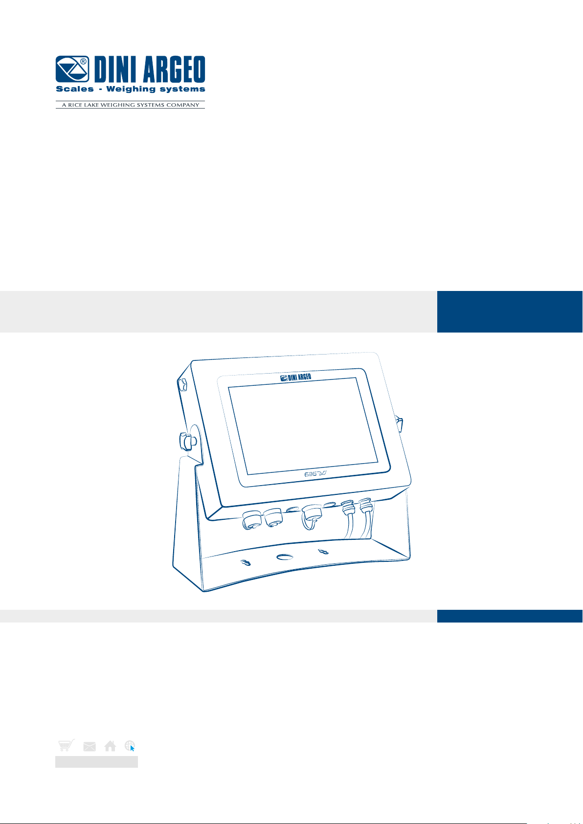
6116EVO
Industrial touchscreen PC with integrated scale input
ENGLISHUSER MANUAL


3
Optimized layout for A4 print.
USER_MAN_ENG_6116EVO
Contents
Introduction 4
Installation 5
Installation requirements 5
Electrical precautions 5
Earthing of the system 7
Dimensional technical drawings 8
6116EVO / 6116EVO-PC 8
6116EVO-DGT 9
Wiring diagrams 10
6116EVO 10
6116EVO-DGT 11
DGX4SP 12
DGT1 13
Technical features 14
Load cell installation 15
Communication 17

4
Optimized layout for A4 print.
USER_MAN_ENG_6116EVO
Dear Customer,
Thank you for purchasing a DINI ARGEO product.
This manual contains all the instructions for the correct installation and commissioning of the 6116EVO industrial PC.
While thanking you for purchasing this product, we would like to draw your attention to some aspects of this manual.
This booklet provides useful information for the correct operation and maintenance of the product to which it refers; it is, therefore,
essential to pay the greatest attention to all those paragraphs that illustrate the simplest and safest way to operate.
The utmost care has been taken in compiling this manual, but reports of any inaccuracies are always welcome.
The instrument is covered by warranty and MUST NOT BE TAMPERED WITH BY THE USER under any circumstances.
Any attempt at repair or modification may expose the user to the danger of electric shock and voids any warranty conditions, relieving
the Manufacturer from all liability.
Any problem with the product must be reported to the manufacturer or to the retailer where it was purchased.
In any case, always TURN OFF THE POWER SUPPLY before any installation or repair operation.
Introduction

5
Optimized layout for A4 print.
USER_MAN_ENG_6116EVO
Installation
Installation requirements
Observe the following conditions for correct installation of the industrial PC and of the load receiver:
• Flat, level support surface.
• Stability and absence of vibrations.
• Absence of aggressive dust and vapours.
• Absence of draughts.
• Make sure that the platform is levelled or that the load cells are evenly supported.
• Moderate temperature and humidity (15°C - 30°C and 40% - 70%).
• Do not install in an environment where there is a risk of explosion.
• All transmitter connections must be made in accordance with applicable regulations in the area and environment of installation.
Observe the electrical precautions listed in the section “Electrical precautions”.
• Ensure that it is correctly earthed, see the relevant section “Earthing of the system”.
• Do not perform welding when the load cells have already been installed.
• If necessary, use watertight sheaths and fittings to protect the load cell cables.
• Any junction boxes must be watertight.
• Anything not expressly described in this manual constitutes improper use of the equipment.
Electrical precautions
• Use a regulated mains supply within ± 10% of the rated voltage.
• The electrical protections (fuses, etc.) are the responsibility of the installer.
• Observe the recommended minimum distances between cables of dierent categories (see table on page 10).
• The following cables must comply with the maximum permissible lengths (see table on page 10), they must be shielded and must
beinserted alone in metal conduits or pipes:
- the load cell extension cables;
- the signal amplifier cables.
The input of the cell and amplifier cables into the PC case must be independent. The cables must be connected directly to the
transmitter terminal block.
• Fit the “RC” filters on all devices that produce electrical noise.
• Connections to load cells and any external device must be as short as possible.
• The cable ends (connectors, leads, terminals, etc.) must be installed correctly; the cable shielding must be kept intact until close to
the connection point.
The sticker shown by the side is applied to the product to warn the user of the electrical hazard:
• - RISK OF ELECTRIC SHOCK
• - DO NOT DISASSEMBLE THE APPLIANCE
• - COMPLETELY DISCONNECT THE POWER SUPPLY TO THE APPLIANCE BEFORE PERFORMING ANY MAINTENANCE.
This manual suits for next models
1
Table of contents
Other Dini Argeo Industrial PC manuals

Popular Industrial PC manuals by other brands


Dell
Dell Embedded Box PC 5000 Installation and operation manual

IBASE Technology
IBASE Technology ASB200-918 Series user manual

Lenovo
Lenovo ThinkCentre M90q Hardware Maintenance Manual

IXXAT
IXXAT Econ 100 Hardware manual

Kontron
Kontron KBox A-151-TGL user guide

AXIOMTEK
AXIOMTEK ICO500-518 Series user manual