Dini Argeo DFW User manual

USER MANUAL
INDICATOR, REPEATER, TRANSMITTER OF WEIGHT “DFW”
SERIES
Review
3.17
Last update
18/11/2014

Page intentionally left blank

USER MANUAL SERIES INDICATORS DFW
Index
1 INTRODUCTION ........................................................................................................................................6
2 MAIN TECHNICAL SPECIFICATION ...........................................................................................................8
3 WIRING AND POWER ...............................................................................................................................9
3.1 CONNECTING THE WEIGHING SYSTEM................................................................................................9
3.2 POWER SUPPLY ....................................................................................................................................9
3.2.1 INTERNAL POWER CONNECTION 110-240 VAC ................................................................................ 9
3.2.2 CONNECTING EXTERNAL POWER SUPPLY 110-240 VAC ............................................................. 10
3.3 BATTERY POWER....................................................................................................................................10
3.3.1 CHARGE THE INTERNAL BATTERY RECHARGEABLE ..................................................................... 10
3.3.2 POWER SUPPLY WITH 4 BATTERIES TYPE “AA” ........................................................................... 11
3.3.3 INSERTING AND REMOVING BATTERY TYPE “AA”....................................................................... 11
3.3.4 REPORTING BATTERY LEVEL ........................................................................................................ 11
3.3.5 INDICATOR CONNECTED TO THE PRINTER, BATTERY OPERATED................................................ 12
3.4 POWER TO PC USING USB CONNECTOR ............................................................................................12
4 TURNING ON / OFF THE INSTRUMENT...................................................................................................13
4.1 TURNING ON ...........................................................................................................................................13
4.2 AUTOZERO AT START-UP ...................................................................................................................13
4.3 TURNING OFF..........................................................................................................................................13
5 FRONT PANEL KEYS AND INDICATORS ...................................................................................................14
5.1 FRONT PANEL KEYS AND INDICATORS (5 key version) ......................................................................14
5.1.1 NUMERIC INPUT WITH THE 5-KEY KEYPAD .................................................................................... 16
5.2 KEY FUNCTION IN THE VERSION 17-KEY ................................................................................................17
5.3 MODE KEY FUNCTION / ................................................................................................................19
5.4 FUNCTION F / FN BUTTON IN COMBINATION WITH NUMERIC KEYS ................................................20
5.5 KEYBOARD LOCK ................................................................................................................................21
5.6 LED’S SIGNAL......................................................................................................................................21
5.7 SYMBOLS ON THE LCD DISPLAY .........................................................................................................22
5.8 LETTERS AND NUMBERS SHOWN ON THE LCD/LED DISPLAY ............................................................23
5.9 INTENSITY BACKLIGHT / LED ..............................................................................................................24
6 BASIC FUNCTIONS ..................................................................................................................................25
6.1 ZERO SCALE ........................................................................................................................................25
6.2 TARE OPERATIONS .............................................................................................................................25
6.2.1 SEMI-AUTOMATIC TARE .............................................................................................................. 25
6.2.2 ENTERING THE MANUAL TARE FROM KEYBOARD....................................................................... 25

6.2.3 CANCELLING A TARE .................................................................................................................... 25
6.2.4 AUTOMATIC/LOCKED/UNLOCKED/DISABLED TARE SELECTION.................................................. 26
6.3 LIMITATION OF THE TARE FUNCTIONS ..............................................................................................26
6.4 AUTO POWER OFF FUNCTION ...........................................................................................................26
6.5 AUTOMATIC STAND-BY FUNCTION....................................................................................................27
6.6 DIVISION OF FLOW IN MOST FIELDS..................................................................................................27
6.7 REMOTE CONTROL (OPTIONAL).........................................................................................................27
6.7.1 NINETEEN-KEY IR REMOTE CONTROL.......................................................................................... 28
6.7.2 SIX-KEY RD REMOTE CONTROL.................................................................................................... 28
6.8 DATE/TIME ADJUSTMENT (OPTIONAL OR INCLUDED DEPENDING ON THE MODEL).......................29
6.9 “SCREEN SAVER” FUNCTION (OPTIONAL OR INCLUDED DEPENDING ON THE MODEL)....................29
6.10 CONDITIONS FOR PERFORMING THE WEIGH AND PRINTS................................................................30
6.10.1 EXECUTING PRINTOUTS WITH NON APPROVED SCALES............................................................. 30
6.10.2 LEGAL FOR TRADE SCALES PRINTING. ......................................................................................... 30
6.10.3 NOTES ON THE PRINTS ................................................................................................................ 30
6.11 REENABLING THE PRINTOUTS AND THE INDICATOR FUNCTIONS .....................................................31
6.12 DISPLAY OF METRIC DATA (info)........................................................................................................31
7 ADDITIONAL FUNCTIONS OF THE 17-KEY INDICATOR............................................................................32
7.1 STORED TARE MEMORY VALUES .......................................................................................................32
7.2 ENTERING THE IDENTIFICATION CODE ..............................................................................................32
7.2.1 LOCKED / UNLOCKED CODE SELECTION ...................................................................................... 33
7.3 REPETITION OF THE LAST PRINTOUT MADE ......................................................................................33
8 SELECTABLE OPERATING MODES...........................................................................................................33
8.1 UNIT OF MEASURE/POUNDS CONVERSION () .............................................................................34
8.2 NET/GROSS SWITCH () ...............................................................................................................34
8.3 SET POINT ON THE GROSS OR ON THE NET WEIGHT ( / ) .................................................34
8.3.1 OPERATION.................................................................................................................................. 34
8.3.2 INSERTING SETPOINT................................................................................................................... 34
8.4 INPUT/OUTPUT () ....................................................................................................................35
8.4.1 PROCEDURE ................................................................................................................................. 35
8.4.2 CANCELLATION WEIGH............................................................................................................... 35
8.5 APPROVED TRANSMISSION OF WEIGHT TO PC WITH ALIBI MEMORY () ...............................35
8.5.1 PROCESS FOR STORAGE............................................................................................................. 35
8.5.2 READING OF THE WEIGHS CARRIED OUT .................................................................................... 36
8.5.3 CANCELLATION OF THE ALIBI MEMORY ...................................................................................... 36
8.6 +/- TOLERANCE CHECK () .........................................................................................................37
8.6.1 PROCEDURE AND STATEMENT OF TOLERANCE .......................................................................... 37
8.6.2 ACOUSTIC SIGNAL........................................................................................................................ 38
8.6.3 PRINT ........................................................................................................................................... 38
8.7 SAMPLE WEIGHT PERCENTAGE ()..............................................................................................39

USER MANUAL SERIES INDICATORS DFW
8.7.1 SAMPLING PROCEDURE............................................................................................................... 39
8.7.2 ERROR “” DUE TO WEIGHT INSTABILITY DURING THE SAMPLING AND MINIMUM
WEIGHT OF THE SAMPLE ......................................................................................................................... 39
8.7.3 SETTING THE SAMPLING INTERVAL............................................................................................. 39
8.7.4 PRINTING ..................................................................................................................................... 40
8.8 DISPLAY WITH SENSITIVITY X 10 ()(TO BE USED IN TESTING DURING THE CALIBRATION) .......40
8.9 HOLD: FREEZING THE WEIGHT ON THE DISPLAY ()......................................................................40
8.10 WEIGHT PEAKS DETECTION ()....................................................................................................41
8.10.1 SETTING SAMPLING TIME............................................................................................................ 41
8.11 HORIZONTAL TOTALIZER (Sum of lots) () ............................................................................42
8.11.1 TOTALISATION OPERATIONS ....................................................................................................... 42
8.11.2 DISPLAYIN PARTIAL TOTAL .......................................................................................................... 42
8.11.3 TOTALISATION WITH PRINTING................................................................................................... 43
8.11.4 PRINTING AND ZEROING OF THE TOTALS.................................................................................... 43
8.11.5 FIELD OF TOTALISATION AND AUTOMATIC PRINT OF THE PARTIAL TOTAL................................ 43
8.11.6 MEMORY STORAGES (only for 17-key indicator)......................................................................... 44
8.12 VERTICAL TOTALIZER (Sum by recipe) () .............................................................................44
8.13 PIECE COUNTING ()....................................................................................................................44
8.13.1 COUNTING PROCEDURE WITH REFERENCE................................................................................. 44
8.13.2 ERROR “” FOR WEIGHT INSTABILITY DURING THE SAMPLING AND MINIMUM WEIGHT
OF THE SAMPLE........................................................................................................................................ 45
8.13.3 SETTING THE SAMPLING INTERVAL............................................................................................. 45
8.13.4 COUNTING WITH INTRODUCTION OF THE AVERAGE PIECE WEIGHT ......................................... 46
8.13.5 PIECE COUNTING IN EXTRACTION. .............................................................................................. 46
8.13.6 PRINTING IN THE COUNTING MODE ........................................................................................... 46
9 USE THE INDICATOR AS WEIGHT REPEATER ..........................................................................................47
9.1 UNIVERSAL SINGLE SCALE REPEATER ().....................................................................................47
9.2 MONO-MULTISCALE REPEATER () ...........................................................................................47
9.2.1 OPERATION.................................................................................................................................. 48
9.2.2 KEYS MAP REPEATED FROM MASTER IN VIEW OF A SLAVE........................................................ 48
9.2.3 SLAVE SELECTION / SUM ............................................................................................................. 49
9.2.4 TARE EXECUTION IN SUM MODE................................................................................................. 49
9.2.5 EXECUTION OF THE PRINTS ......................................................................................................... 49
9.2.6 WEIGHS LIST OPTIONS (STANDARD IN THE MODEL DFWPM10USB).......................................... 49
9.2.7 TURNING OFF THE MASTER AND SLAVES.................................................................................... 51
10 INSTRUMENT MESSAGES WHILE IN USE ................................................................................................52

6
1INTRODUCTION
The purpose of this manual is to help the user get to know the weight indicator’s various functioning
modes, the keys’ functions and the display indications.
We advise to carefully follow the instructions for programming the weight indicator; by taking actions
not indicated this manual, one could cause the scale to not work properly.
In addition to having all the characteristics of a high precision scale, the indicator has the unit of measure /
pounds conversion function, the gross weight / net weight conversion, set point on gross weight or net
weight, in/out weigh, universal repeater single scale,single-multiscale repeater, approved transmission of
the weight to PC with alibi memory, +/- tolerance check, sample weight percentage, freezing the weight on
the display, peak detector, weighs totaliser and piece counter.
The indicator adapts itself to normal weighing applications in either industrial settings, such as during
factory production processes, or that of commerce, such as legal for trade applications, also satisfying the
frequently needed ability to transmit and print the data through its two bidirectional serial ports.
This manual has been made as carefully and exactly as possible; in any case, your suggestions are always
welcome.
This instrument is covered under warranty provided that IT HAS NOT BEEN OPENED BY THE USER for any
reason.
Any attempt to repair or alter the unit can expose the user to the danger of electric shock and will void any
warranty condition.
If any problem with the unit or system has been experienced please notify the manufacturer or the dealer
from which the instrument was acquired. In any case REMOVE POWER before any operation.
The instrument is isolated from the area of dangerous voltage and user accessible parts.
Do not pour liquids on the indicator
Do not use solvents to clean the indicator
Do not expose instrument to either direct sun light or any heat sources
Always mount the indicator and platform in a vibration free setting
Do not install in an environment with any risk of explosion
Everything not expressly described in this manual has to be considered as improper use of the equipment.
Do not install in an environment with danger of explosion
WARNING

INTRODUCTION
7
The crossed-out wheeled bin on the product means that at the product end of life, it must
be taken to separate collection or to the reseller when a new equivalent type of
equipment is purchased. The adequate differentiated refuse collection in having the
product recycled, helps to avoid possible negative effects on the environment and health
and supports the recycling of the materials of which the equipment is made. The unlawful
disposal of the product by the user will entail fines foreseen by the current regulations.
Symbols used in the manual
CAUTION!
This operation must be performed by qualified personnel
CAUTION!
Symbol refer to work on high-energy lines: only qualified personnel may require or
perform this operation
CE COMPLIANCE
IDENTIFICATION OF ACCURACY CLASS.
It means that you are describing an advance feature (hence intended for technical
personnel) that will be detailed in the technical manual.
MAIN TECHNICAL SPECIFICATION
8
2MAIN TECHNICAL SPECIFICATION
Supply
Model
Internal power
supply
110-240Vac
50-60Hz
External power
supply
110-240Vac
50-60Hz
Battery
internal
rechargeable
4 batteryes
type
“AA”
Power
supply
from PC via
USB
connector
Recharger
DFW
•
•
DFWL
•
•
DFWLB
•
•
DFWLI
•
DFWLIB
•
•
DFWLIDCC
•
DFWLID
•
•
DFWLAP
•
•
DFWLKR
•
•
DFWPM
•
•
Operating temperature
From -15 to +40 °C (5 to 104 °F) (with even temperature).
General functions
- Operation with a balance
- Subtractive tare over the entire range.
- Auto power off from 1 to 255 minutes programmable, or off.
- Low battery warning on display through symbols and message "" written on display.

WIRING AND POWER
9
3WIRING AND POWER
3.1 CONNECTING THE WEIGHING SYSTEM
The connection of the system depends on the weighing platform and indicator model purchased
If required, connect the cable from the weighing system to the connector on the cable from the indicator of
weight or place directly on it.
For the operation of the platform, refer to the corresponding manual.
3.2 POWER SUPPLY
The connection to the mains supply depends on the type of power supplied (refer to the table in paragraph
2)
For connection to the mains supply must be complied with safety standard including the use of a “clean”
line and free of noise interference from other electronic devices.
If the instrument is powered properly, the light turn on on power-on LED on the front panel.
In addition, if there is an internal rechargeable battery, it will be reacharged.
3.2.1 INTERNAL POWER CONNECTION 110-240 VAC
Plug the cable from the indicator to the network (110-240 Vac).
WIRING AND POWER
10
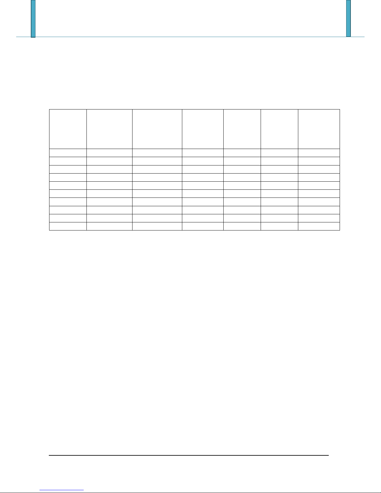
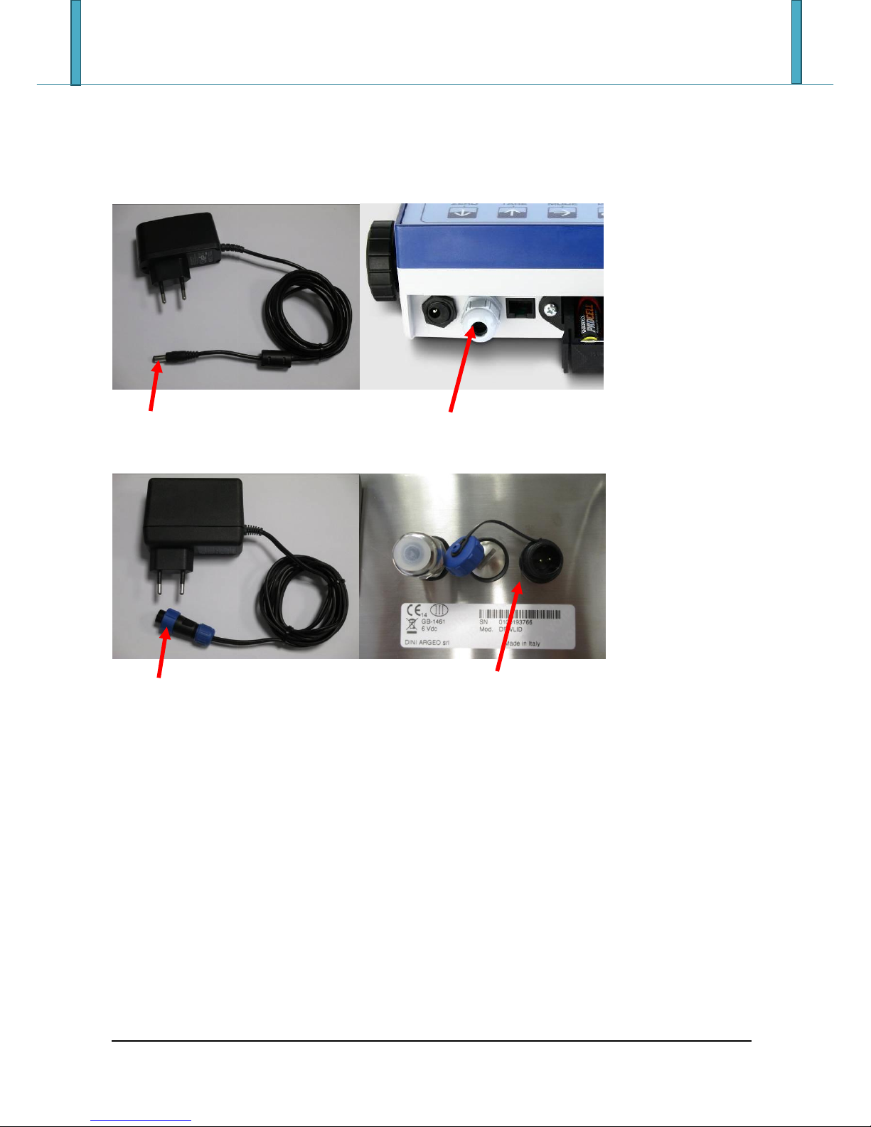
3.2.2 CONNECTING EXTERNAL POWER SUPPLY 110-240 VAC
Connect the power supply to the mains (110-240 VAC) and the plug to the socket on the indicator.
Example 1
Plug power supply Socket on the indicator
Esempio 2
Plug power supply Socket on the indicator
3.3 BATTERY POWER
The instrument may provide for the use in battery (refer to the table in paragraph 2).
In this case you can use the tool even without mains supply, using this only for the possible charge (in case
of internal rechargeable battery).
3.3.1 CHARGE THE INTERNAL BATTERY RECHARGEABLE
To recharge the battery, connect the instrument to the network as described in the previous paragraph.
The battery must be supplied by the manufacturer.

WIRING AND POWER
11
Make the complete recharge of the battery (12 hours) at the first installation of the instrument.
To avoid the deterioration of the rechargeable battery:
-In condition of normal use is recommended to never leave it partially or fully discharged; fully recharge
it at least once a week.
-In case of prolonged periods of non-use, must:
1) fully recharge the battery before shutting down the system;
2) perform a fully recharge every 3 months.
3.3.2 POWER SUPPLY WITH 4 BATTERIES TYPE “AA”
The indicator can be powered with 4 rechargeable or non-rechargeable batteries to insert in the removable
batteries box.
If powered by AA batteries for “rechargeable” batteries (not included), charging the same must be done
externally through consideration charger (not supplied).
3.3.3 INSERTING AND REMOVING BATTERY TYPE “AA”
Remove the battery box as shown in the following picture:
Remove any existing batteries and insert 4 new in the spaces according to the polarity indicated above.
Replace the battery box.
3.3.4 REPORTING BATTERY LEVEL
In models with LCD display the charge level of the battery, if present, is indicated in the weighing phase
with the corresponding symbol:
- : full charged
- : partially charged
- : low battery: connect the indicator to the mains for charging the internal battery or replace the AA
batteries.
In case of low battery, appears for a few second the message "" on the display (voltage at
minimum level)

WIRING AND POWER
12
For correct reporting of the charge may be necessary to set the type of power ( ).
The display also indicates when the battery is being charged:
STEP CHARGING: …
CHARGING COMPLETE:
During recharging, the instrument can normally be used.
The instrument switches off automatically when the voltage drops belove the minimum level.
It’s possible to display the battery level also on the power-on. (see paragraph “POWER AND POWER-ON)
In this case the indicator shows in sequence several messages including:
where is a number from 0 to 100 that indicates the battery level.
3.3.5 INDICATOR CONNECTED TO THE PRINTER, BATTERY OPERATED
If a system is composed of an indicator connected to a printer, both powered by battery, the printer,
usually in STAND-BY, it is powered only when printing; at the end of the printing, the printing automatically
returns to STAND-BY. This function is useful in order to reduce the energy absorbed by the battery when
the printer is not used.
In this configuration, if you have the need to power the printer to replace the paper and for other
operations:
-Press the ZERO button for a few seconds.
-The display show the flashing message “”.
-The printer is turned on; perform the desired operation.
-Press any key to exit.
3.4 POWER TO PC USING USB CONNECTOR
If the instrument so provides, it is possible to power the indicator from the USB port connected to PC.
Connect the appropriate USB port on the top of the instrument to the USB port of the PC through a
standard PC cable, as shown in the following picture:

TURNING ON / OFF THE INSTRUMENT
13
4TURNING ON / OFF THE INSTRUMENT
4.1 TURNING ON
TO TURN ON the instrument press the C key until the indicator turns on; then release.
The display shows
is the installed software version
The instrument turns on all the display segments and symbols
Then displays
range of channel 1
(or if you select the operating mode “”, or if you select the
operating mode “”)
where is a number from 0 to 100 that indicate the battery level in percentage.
After this, it shows the programmed capacity and the minimum division, "" (in case of NOT approved
instrument) or “" (in case of approved instrument), the g gravity value, and finally it executes a
countdown (self-check).
4.2 AUTOZERO AT START-UP
The indicator has an “auto zero at start-up” function: in other words it means that if at start-up a weight
within +/- 10% of the capacity is detected, it will be zeroed; if the weight is not within this tolerance, with a
non approved instrument the display shows the present weight after a few instants, while with an
approved instrument “” is shown continuously on the display, until the weight does not re-enter
within this tolerance; the auto zero function at start-up may be disabled in the set-up environment (only
with non approved instrument); see:
>> >> >> ( ).
4.3 TURNING OFF
TO TURN OFF the instrument keep the C key pressed until the ““message appears on the
display; then release the key.
TO RESTART the instrument keep the C key pressed for 8 seconds long: the indicator will turn off, then
release the key and the indicator will automatically turn on.

FRONT PANEL KEYS AND INDICATORS
14
5FRONT PANEL KEYS AND INDICATORS
The front panel of the indicator is designed for quick and simple weighing applications. It consists of a
display with 6 digits, 25 mm in height, 7 LED indicators (depending on the model), and a 5-key water-proof
film keyboard.
LEDS, if present, will be active during weighing to indicate the operative status (see paragraph “WARNING
LAMPS”).
If the indicator has an LCD display, while weighing, various multifunction symbols indicating the functioning
status will turn on (see section “SYMBOLS ON THE LCD DISPLAY”).
5.1 FRONT PANEL KEYS AND INDICATORS (5 key version)
DFW LCD DISPLAY VERSION
1
2

FRONT PANEL KEYS AND INDICATORS
15
DFW LED DISPLAY VERSION
SCALE KEY
FUNCTION
ZERO
- Zeros the displayed gross weight, if it is within +/- 2% of the total capacity.
- Cancels the negative tare value.
- When entering numbers it decreases the digit to be modified.
TARE
- If pressed for an instant it carries out the semiautomatic tare.
- If pressed at length it allows entering the manual tare from keyboard.
- Cancels the negative tare value.
- In the numeric input phase it increases the digit to be modified.
MODE /
- Performs a specific function of the operating mode set in the setup environment. See
paragraphs “MODE KEY FUNCTION / ” and “SELECTABLE OPERATING MODES”.
- In the numeric input phase it selects the digit to be modified, from left to right.
- In totalizator modes, if pressed twice consecutively, it allows to enter in a specific
menu to set the parameters of the totalizations.
1
2
3
4
5
6
7
8

FRONT PANEL KEYS AND INDICATORS
16
ENTER / PRINT
- It carries out a specific function of the operating mode set in the set-up environment.
- In the numeric input phase, it confirms the entry made.
- In the SET-UP, it allows to enter a step or to confirm a parameter within a step.
- It transmits the data from the serial port dedicated to the printer.
C / i
- It turns the instrument on and off.
- In the numeric input phase, it quickly zeros the present value.
- In the SET-UP, it allows to exit a step without confirming the change made;
in the 5-key indicator:
- Allows viewing the scale’s metric information: capacity, division, minimum weigh for
each configured range.
5.1.1 NUMERIC INPUT WITH THE 5-KEY KEYPAD
With the 5-key keypad, you can enter a numeric value in the input stage with the following keys:
ZERO decreases the blinking digit.
TARE increases the blinking digit.
MODE select the digit to be modified (blinking); the scrolling of the digits takes place from left to
right.
Cif pressed for an instant it quickly zeros the present value; if pressed at length it allows to
return to weighing without saving the changes made.
ENTER Confirm the setting and leave the input.

FRONT PANEL KEYS AND INDICATORS
17
5.2 KEY FUNCTION IN THE VERSION 17-KEY
Example of a 17-key keypad, picture 1
Example of a 17-key keypad, picture 2
1
2
2
1
3
4
5
6
7
8

FRONT PANEL KEYS AND INDICATORS
18
SCALE KEY
FUNCTION
ZERO
- Zeros the displayed gross weight, if it is within +/- 2% of the total capacity.
- Cancels the negative tare value.
- When entering numbers it decreases the digit to be modified.
TARE
- If pressed for an instant it carries out the semiautomatic tare.
- If pressed at length it allows entering the manual tare from keyboard.
- Cancels the negative tare value.
- In the numeric input phase it increases the digit to be modified.
MODE /
- It carries out a specific function of the operating mode set in the set-up environment.
See paragraphs “MODE KEY FUNCTION / ” and “SELECTABLE OPERATING MODES”.
- In the numeric input phase it selects the digit to be modified, from left to right.
- In totalizator modes, if pressed twice consecutively, it allows to enter in a specific
menu to set the parameters of the totalizations.
ENTER / PRINT
- It carries out a specific function of the operating mode set in the set-up environment.
- In the numeric input phase, it confirms the entry made.
- In the SET-UP, it allows to enter a step or to confirm a parameter within a step.
- It transmits the data from the serial port dedicated to the printer.
C
- It turns the instrument on and off.
- In the numeric input phase, it quickly zeros the present value.
- In the set-up environment, it allows to exit a step without confirming the change
made.
F / Fn
- It allows to select the desired function, see sections “FUNCTION F / FN BUTTON IN
COMBINATION WITH NUMERIC KEYS” and “ADDITIONAL FUNCTIONS OF THE 17 KEYS”
- If pressed at length it allows to set the display intensity
( ),“”parameter).
i / .
- The “i” key allows to view the scale’s metric information: capacity, division, minimum
weigh for each configured range.
- In the numeric input phase it allows to enter the decimal point.
NUMERIC
KEYBOARD
- In the numeric input phase it allows to enter the desired value.

FRONT PANEL KEYS AND INDICATORS
19
5.3 MODE KEY FUNCTION /
Function
key
Effect
Key
Effect
Key
STANDARD
MODE
→
Switch Kg/Lb
NET /GROSS
MODE
→
Switch Net/Gross
SETPOINT
ENTER
Type value
ENTER
IN /OUT
MODE
→
In weigh
ENTER
Out weigh
ALIBI MEMORY
MODE
→
Type rewriting ID
ENTER
Type ID
ENTER
CONTROLLO
TOLLERANZA
MODE
→
Target
ENTER
Tol -
>>>>>
ENTER
Tol +
ENTER
Min weight
ENTER
PERCENTAGE
MODE
→
Type % value
ENTER
Mode key: a)
Switch % / weight.
Mode key 2 sec.: b)
Sample
DISPLAY X 10
MODE
→
Enable/disable x10
HOLD
MODE
→
Enable/disable hold
PEAK
MODE
→
Enable/disable peak
TOTALIZER
MODE
→
Single weighing
ENTER
Total
ENTER
Grand total
PIECE COUNTING
MODE
→
Type PCS NR.
ENTER
Mode key: a)
Switch PCS/weight.
Mode key 2 sec.: b)
sample

FRONT PANEL KEYS AND INDICATORS
20
5.4 FUNCTION F / FN BUTTON IN COMBINATION WITH NUMERIC KEYS
Key
Key
Effect
Continue with
Key
/
+
0
Lock/unlock
1
Recall tare (database)
Type memory (1..30)
ENTER
2
Lock/unlock tare
3
Enter ID
Type memory (1 or 2)
ENTER
4
Lock/unlock ID
5
Piece counting
Type piece counting
6
Totalizer
Visualization of general total
7
Piece counting
Change sampling time
8
Change data/ time
9
Insert tare (database)
1. Type memory (1..30)
ENTER
2. Type value
ENTER
Other manuals for DFW
1
This manual suits for next models
9
Table of contents
Other Dini Argeo Touch Panel manuals


