KNX Technical Reference Manual
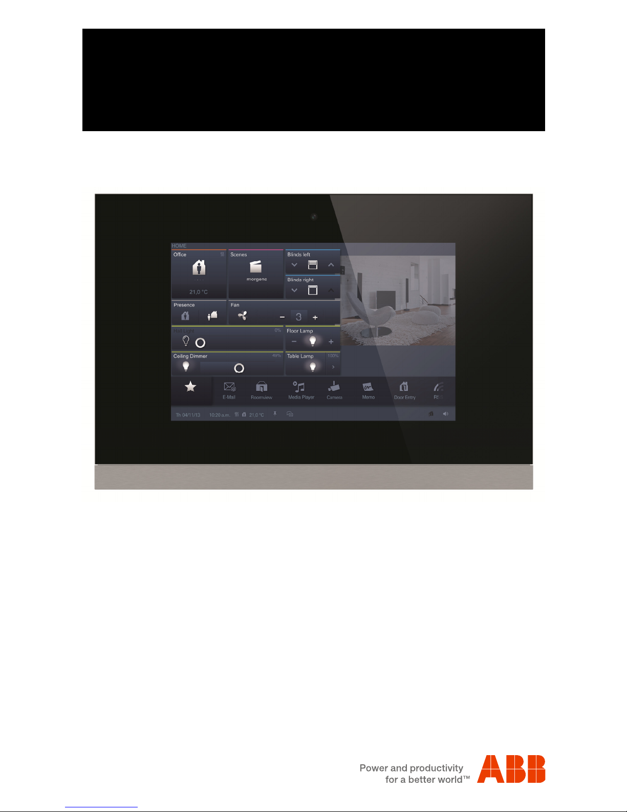
Busch-ComfortTouch®
KNX Technical Reference Manual | 1473-1-8039 — 3 —
9Overview of IP-Project 3 (IPP) ............................................................................................................................... 37
9.1 Start of IP-Project 3............................................................................................................................... 37
9.2 Screen areas in IP-Project 3 ................................................................................................................. 38
9.3 Explanation of the basic structure (Terms)............................................................................................ 39
9.3.1 Areas..................................................................................................................................................... 39
9.3.1.1 Library area........................................................................................................................................... 39
9.3.1.2 Working area......................................................................................................................................... 40
9.3.1.3 Parameter area ..................................................................................................................................... 41
9.3.1.4 Help area .............................................................................................................................................. 41
9.3.1.5 Levels.................................................................................................................................................... 42
9.4 Basic operation (Copying functions) ..................................................................................................... 44
9.4.1 Copying a project .................................................................................................................................. 44
9.4.2 Moving / copying pages and control elements ...................................................................................... 44
9.4.3 Cross references................................................................................................................................... 44
9.4.4 Print....................................................................................................................................................... 44
10 Project planning ..................................................................................................................................................... 45
10.1 Recommended sequence of project planning ....................................................................................... 45
10.2 Consistency check ................................................................................................................................ 45
10.3 Loading the project into the Busch-ComfortTouch®.............................................................................. 46
11 Operation ............................................................................................................................................................... 47
11.1 Basic structure of page types................................................................................................................ 47
11.2 Status bar.............................................................................................................................................. 48
11.3 Navigation bar....................................................................................................................................... 48
11.4 Page types of the Busch-ComfortTouch®.............................................................................................. 49
11.4.1 Functional start page............................................................................................................................. 49
11.4.2 Start page with floor plan ...................................................................................................................... 50
11.4.3 Operating page functions...................................................................................................................... 51
11.4.4 Operating pages with image of room .................................................................................................... 52
11.4.5 Application page ................................................................................................................................... 52
12 Maintenance .......................................................................................................................................................... 53
12.1 Cleaning................................................................................................................................................ 53
13 Description of functions.......................................................................................................................................... 54
13.1 Device information ................................................................................................................................ 54
13.2 System settings..................................................................................................................................... 55
13.2.1 Camera adjustment............................................................................................................................... 56
13.3 Import and export of files....................................................................................................................... 57
13.4 Operating functions:.............................................................................................................................. 58
13.4.1 Push-button (Switch)............................................................................................................................. 58
13.4.2 Dimmer ................................................................................................................................................. 58
13.4.3 Roller shutter / Blind.............................................................................................................................. 59
13.4.4 Scenes and sequences......................................................................................................................... 59
13.4.5 Value and text ....................................................................................................................................... 59
13.4.6 Room temperature controller (RTC)...................................................................................................... 59
13.4.7 Control element "KNX Audio"................................................................................................................ 60
13.4.8 RGB control .......................................................................................................................................... 60
13.4.9 Philips Hue control element .................................................................................................................. 61
13.4.10 Step switch............................................................................................................................................ 61
13.5 Room temperature control .................................................................................................................... 62
13.6 Time and date display........................................................................................................................... 62
13.7 Image messages................................................................................................................................... 63
13.8 Voice messages.................................................................................................................................... 64
13.9 Scenes and sequences......................................................................................................................... 65
13.10 Weekly timers ....................................................................................................................................... 67
13.11 Simpls weekly program......................................................................................................................... 68
13.12 Presence simulation.............................................................................................................................. 69
13.13 Access control....................................................................................................................................... 69
13.14 Set mobile control ................................................................................................................................. 70