Dino-Power DP6388B Operation instructions

Owner’s Manual
For professional Use only
Do not use this equipment before reading this manual!
Airless Paint Sprayer
International Model
Original instruction
DP6388B
Ningbo Dino-power Machinery Co.,Ltd
No 168 MingGuang Road, Yinzhou District, Ningbo, China
www.dpairless.com or www.airlesspaintsprayer-pump.com
www.dino-power.com
NOTE: This manual contains important warnings and
instructions. Please read and retain for
reference

a
e
a
s
a
a
e
Table of Contents
Safety Precautions.......................................................... 2
General Description.........................................................4
Technical Parameter........................................................4
Operation............................................................................ 4
Setup.................................................................................... 4
Preparing to Paint.............................................................5
Painting................................................................................5
Electronic Pressure Control Indicators..................... 5
Pressure Relief Procedure............................................ 6
Spraying.............................................................................. 6
Spraying Technique......................................................... 6
Practice................................................................................7
Shutdown and Cleaning..................................................7
Troubleshooting................................................................ 8
Parts Listings.................................................................... 10
Main Assembly............................................................10
Motor Assembly..........................................................11
Gear Box Assembly...................................................12
Suction Set Assembly............................................... 12
Stand Assembly.......................................................... 12
Fluid Section Assembly............................................ 13
Tip Selection................................................................ 14
Selecting Tip Hose Size................................................. 14
Choosing The Correct Tip..............................................14
Tip Hose Size.................................................................... 14
Fan width............................................................................ 14
Understanding Tip Number........................................... 14
Reversible Tip Selection Chart....................................15
Safety Precautions
This manual Contains Information that must be read and
understood before using the equipment, When you come to an
area thathas one of the following symbols, pay particular
attention and
N
m
O
a
T
k
E
e
:
c
N
e
o
rt
te
a
s
in
g
t
i
o
ve
he
im
ed
po
th
rt
e
an
s
t
a
i
f
n
e
f
g
o
u
rm
ar
a
d
ti
.
WARNING
This Symbol indicates a potential hazard that may cause
serious injury or loss of life. Important safety information
will follow.
CAUTION
This symbol indicates a potential hazard to you or to the
equipment. Important information that tells how to prevent
damage to the equipment or how to avoid causes of minor
injur ies will fo llow.
NOTE: Notes giv import nt inform tion which hould
be given speci l tt ntion.
WARNING
Airless units develop extremely high spraying pressures.
·Never put your fingers, hands or any other parts of the
body in to the spray jet.
·Never point the spray gun at yourself or anybody else.
·Never use the spray gun without the safety guard.
Attention! Danger of injury by injection!
In case of injury to sk in caused by coating materials or
solvents consult a doctor immediately. Inform the doctor of the
type of coationg material or cleaning agent with which the injury was
caused.
The operating instructions state that the following points
must always be observed before starting up:
1.
Faulty units should not be used.
2.
Secure spray gun using the safety catch on the trigger
3.
Ensure that the unit isproperly earthed.
4.Check the permissible operating pressure.
5.Check all connections for leaks.
The instructions regarding regular cleaning and
maintenance of the unit must be strictly observed.
Before any work is done on the unit or for every break in
work the following rules must be observed:
1.
Release the pressure from the spray gun and hose.
2.
Secure the spray gun using the safety catch on the
trigger.
3.
Turn off the motor.
Be safety-conscious!
All local regulation in force must be observed.
In order to ensure safe operation of the airless systems
the safety regulations listed below must be followed:
1.In
order to avoid dangers, read the operating instructions
carefully and follow the instructions laid down in them.
2.Do not use materials with flash point below 2
1℃
(7
0℉H
).
3.The use of this unit is prohibited in workshops which are
covered under the explosion prevention regulations.
4.
Never spray near sources of ignition; e.g. open flames,
cigarettes also cigars and pipes are sources of ignition
- sparks, hot wires and hot surfaces, etc.
5.Attention! Danger of injury by injection!
Never point the spray gun at yourself or anyone else.
Never put your fingers or hands into the spray jet. The
very high spraying pressures can cause very serious
injuries. Never use the spray gun without the safety guard.
When Installing an d removing the t ip and d uring bre aks in
wo rk the spray gun must alw ays be secured, so that it
cannot be activated.
6.
Wear respiratory equipment when spraying. The opera tor
must be provided w ith a protective mas k.
In order to prevent work related illness, the ma nufacturer
'
s
ag ents used must be observed when prepa ring, wo rking
with and cleaning the unit. Protective clothing, gloves and
in
certain cases, protective skin cre am are n ecessary to
protect the skin.
7.The spray gun and high pressure hose betw een the unit
an d spr ay gun mus t be of a sufficient standard for the
pressure p roduced in the unit.
The permissible operating pressure for the high- pressure
ho se, the manufacturer and the da te of manufacture must be
indicated by a permanent identification ma rking on the
ho se. Furth ermore, it must be constructed so that the
electrical re sistance between the connections to th e unit
an
d the sp ray gun is equal to or less than one megohm.
8.Und er certain cond itions the follow speed can cause an
electrostatic charge on the unit. This could cause sparks
or flames on discharging. It is, therefore, important that
the un it is always earthed over the electrical in stallation.
The con ta ct should be made us in g a sho ckpro of socket
ea rthed in accord ance with the re gulations.
9.Forbidden to use of electrostatic atomising and spraying
equipment with machines not specifically designed for this
equipm ent, because it may result in serious hazards for
the operators;
10.
Pay attention to hazards resulting from contact with and/or
breathing of toxic materials, gases, mists and vapours which
may be created by operation of the machine.
11.
Before installation and usage, visually inspection for damage
on hoses which may be subjected to friction should be done.
2.

3.
9. Attention! Please observe the following when working
inside and outside:
No Solvent Gasses Should be carried to the unit. No
solvent gasses should from near the unit. Set up the unit
on the opposite side to the object being Sprayed. When
spraying out doors, take the wind direction in to account.
When working in doors there must be sufficient ventilation
to ensure that the solvent gasses are carried away.A
minimum distance of 6.1m(20') must be observed
between the unit and object being sprayed.
10.
Extraction equipment Should be installed by the user in
accordance with the local regulations.
11. The objects being sprayed must be earthed.
12.
When cleaning the unit, solvent should never be sprayed
intoa container with only a small opening(bunghole). An
explosive gas/air mixture is likely to form. The container
must be earthed.
13. Cleaning the unit.
A harsh jet should never be used to spray the unit. In
particulara high-pressure cleaner or high-pressure steam
cleaner should never be used. There is a danger that
water will penetrate into the unit and causea short-circuit.
14.
Pulling the trigger causes a recoil force to the hand that is
holding the spray gun.
The recoil force of the spray gun is particularly powerful
when the tip has been removed anda high pressure has
been set on the airless high-pressure pump. Therefore,
when cleaning without tip set the pressure control valve to
the lowest pressure.
15.
The mains plug should only be disconnected from the
socket when work is being carried out on the electrical
components.
14.
Work or repairs should only be carried out on electrical
equipment by a trained electrician, even if the work is
described in the operating instructions. No liability will be
accepted for incorrectly installed electrics.
15. Positioning when the ground is uneven.
The front of the unit must point downward so that the
machine does not slip away.
HAZARD: INJECTION INJURY- A high pressure stream of
paint produced by this equipment can pierce
the skin and underlying tissues, leading to
serious injury and possible amputation.
DO NOT TREAT AN INJECTION INJURY ASA
SIMPLE CUT! Injection can lead to
amputation. See an physician immediately.
PREVENTION:
·
The maximum operating range of the unit is 221 BAR
(3200 PSI) fluid pressure.
·
Never aim the gun at any part of the body.
·
Never allow any part of the body to come in contact with
stream created by aleak in the fluid hose.
·
Never Put your hand in front of the gun. Gloves will not
provide protection against and injection injury.
·
ALWAYS lock the gun trigger, shut the fluid pump off and
release all pressure before servicing, cleaning the tip
guard, changing tips, or leaving unattended. Pressure will
not be released by turning off the engine. The
PRIME/SPRAY knob must be turned to PRIME to relieve
the pressure. Refer to the PRESSURE RELIEF
PROCEDURE described in this manual.
·
The tip guard must always be in place while spraying. The
tip guard provides some protection against injection
injuries but is mainly a warning device.
·
ALWAYS remove the spray tip before flushing or cleaning
the system.
·
The paint hose can develop leak from wear, kinking and
abuse. A leak is capable of injecting material into the skin.
Inspect the paint hose before each use.
NOTE TO PHYS ICIAN:
Injection in to the skin is a tr aumatic injury. It is
important to theat the injury surgically as soon as
possible. DO NOT delay treatment to research toxicity.
Toxicity is a concern with some coatings injected
directly into the blood stream. Consultation witha
plastic surgeon or reconstructive hand surgeon may be
advisable.
HAZARD: EXPLOSION OR FIRE-Solvent and paint fumes can
explode or ignite, causing property damage and/or
severe injury.
PREVENTION:
·
Fire extinguishing equipment must be present and in go od
wo rking order.
·
Use only conductive or earthed high pre ssure flu id hoses
for airless applic ations, be sure that the gun is earthed
properly through hose connectio ns.
·
The pump mu st be connected to an earthed object. Use
the green earthing wire to connect the p ump to a water
pipe, steel beam, or other electr ically earthed surface.
·
When flushing equipment use the lowest po ssible
pressure.
HAZARD: EXPLOSION HAZARD DUE TO INCOMPATIBLE
MATERIALS- May cause property damage or
severe injury.
PREVENTION:
·
Do not use bleach.
·
Do not use halogenated hydrocarbon solvents such as
methylene chloride and 1,1,1-trichloroethane. They are not
compatible with aluminum and may cause an
explosion. If you are unsure of a material's compatibility
with aluminum, contact your coating's supplier.
HAZARD: GENERAL-May cause property damage or
severe injury.
PREVENTION:
·
This high pressure airless pump is designed to be used
with manufacturer authorized parts only. When using this
pump with parts that do not comply with the minimum
specifications and safety devices of the pump
manufacturer, the user assumes all risks and liabilities.
·
Before each use, check all hoses for cuts, leaks, abrasion
or bulging of cover, as well as damage or movement of
couplings. If you any of these condition exist, replace the
hose immediately. Never repair a paint hose. Replace it
with another earthed hose.
·
Wear protective eyewear.
·
Do not spray on windy days.
Earthing Instructions
This product must be earthed. In the event of an electrical
short circuit, earthing reduces the risk of electric shock by
providing an escape wire for the electric current. This product
is
equipped witha cord having an earthing wire with an
appropriate earthing plug. The plug must be plugged into an
outlet that is properly installed and earthed in accordance with all
local codes and ordinances.
DANGER-Improper installation of the earthing plug can
result in a risk of electric shock.
If repair or replacement of the cord or plug is necessary, do not
connect the green earthing wire to either fla t blade terminal. The
wire with insulation havinga green outer surface with or without
yellow stripes is the earthing wire and must be
connected to the earthing pin.
Check with a qualified electrician or serviceman if the earthing
instructions are not completely understood, or if you are in
doubt as to whether the product is properly earthed. Do not
modify the plug provided. If the plug will not fit the outlet, have
the proper outlet installed by a qualified electrician.

4.
General Description
This airless spraye r is a precision power tool used for spraying
many types of mate rials. R ead and follow this ins truction
manual carefully for prope r operating instructions, and
safety informa tion.
The paint sprayer is compatible with the following water
soluble paints:phenol aldehyde paint series -nitryl paint
series alkyd paint series epoxy resin paint series oxidized
rubber paint series latex paint series etc.
Technical Parameter
Setup
Perform the following procedure before plugging in the power
cord of an electric unit.
1.
Ensure that the suction set and the return hose are
attached and secure.
2.
Using a wrench, attach a minimum of 7.5m 24.6' x 10mm
(1/4”) nylon airless spray hose to the unit. Tighten
securely.
3.
attach an airless spray gun to the spray hose. Using two
wrenches ( one on the gun and one on the hose), tighten
securely.
NOTE: Do not attach the tip to the spray gun yet.
Remove the tip if it is already attached.
WARNING
Make sure all airless hoses and spray guns are electrically
grounded and rated for at least 228 bar (3300 psi) fluid
pressure.
4.
Make sure the pressure control knob is in its OFF position
5.Make sure the ON/OFF switch is in its OFF position.
6.Fill the oil cup with 15g (one tablespoon) of piston sea l
lubricant (piston lube).
CAUTION
Never operate unit for more than ten seconds without
fluid. Operating this unit without fluid will cause
unnecessary wear to the packing.
7.
Make sure the electrical service is correct for the unit.
8.P lug the power cord in t o a proper ly ground ed outlet a t
least 7.6m (25') fr om the spray area.
CAUTION
Always use a minimum 12 gauge, three-wire extension cord
with a grounded plug. Never remove the third prong or use
an adapter.
Preparing a New Sprayer
If this unit is new, it is sh ipped with test flu id in the fluid section
to prevent corrosion during shipment and storage. This fluid
must be thoroughly cleaned out of the system with mineral
spirits before you begin spraying.
Always keep the trigger lock on the spray gun in the
locked position while preparing the system.
1.
Place the suction tube intoa container of mineral spirits
that has a flash point of 60
℃(
140
℉H
) or above.
2.
Place the return hose into a metal waste container.
3.Turn Pressure Control Knob all the way left
(counter-clockwise) to minimum pressure.
Operation:
WARNING
This equipment produces afluid stream at extremely high
pressure. Read and understand the warnings in the
safety precautions section at the front of this manual
before operating this equipment.
4.Move the PRIME/SPRAY valve down to the PRIME
position.
5.
Turn the unit on by moving the ON/OFF switch to the On
position.
6.
Allow the Sprayer to run for 15-30 seconds to flush the
test fluid out through the return hose and into the waste
container.
7.
Turn the unit off by moving the ON/OFF switch to the OFF
position.
Working pressure range
0-2800 psi(0-19MPa,0-193 bar)
Electric motor
6.0A (open frame, universal)
Operating horsepower
1/2
Maximum delivery(with tip)
0.24gpm (0.91lpm)
Paint Hose
1/4 in x 25 ft ( 6.4 mm x 7.5m)
Maximum Tip hole size
0.015 in. (0.38mm)
Weight, sprayer only
16 lb (7.3 kg)
Weight, sprayer,hose & gun
19.2 lb (8.7 kg)
Dimensions(upright):
Length
14.5in (36.8cm)
Width:
12.4in (31.5cm)
Height:
17.9in (45.5cm)
Dimensions(Folded):
Length:
19.3in (49.0cm)
Width:
15.3in (38.9cm)
Height:
29.2in (74.2cm)
Power Cord:
18AWG,3 wire,6ft(1.8m)
Fluid inlet fitting
3/4 in. internal thread (Standard garden hose thread)
Fluid outlet fitting
1/4NPSM external thread
Inlet screen (on suction tube)
35mesh (450 micro)
Wetted parts, pump & hose
Stainless steel, brass, leather, ultra-high molecular
weight polyethylene (UHMWPE), carbide, nylon,
aluminum, PVC, polypropylene, fluroelastomer
Wetted parts, gun
Alu minum , brass, carb ide, nylo n, plated steel,
stainless steel, UHMWPE, zinc
Generator requirement
1500 Watt minimum
Electrical power requirement
230V 50Hz, 15A 1 phase
Storage temperature range
-30°to 160℉(-35°to 71℃)
Operating temperature range
40°to 115℉(4°to 46℃)
Maximum allowable pressure for the
coating material(MPa)
Maximum allowabl e temperature of the
coating material(
℃
)
Typical coating material flow rate(l/min)
Sound power level ( LWA 4 m hem isphere ) dB(A)
97.9
Sound pressure level(LpAAirborne noise
1m away from working station) dB(A)
90
Uncertainty dB(A)
1.5
Vibration valve for spraying gun(
m/s2)
2.391
Uncertainty(
m/ s2 )
0.5
CAUTION
5.
WARNING
Preparing to Pain
Before painting, it is important to make sure that the fluid in the
system is compatible with the paint that is going to be used.
NOTE: Incompatible fluid and paint may cause the
valves to become stuck closed ,which would
require disassembly and cleaning of the
sprayer' s fluid section.
Always keep the trigger lock on the spray gun in the
locked position while preparing the system.
1.place the suction tube intoa container of the appropriate
solvent for the material being sprayed (refer to
recommendations of the material manufacture).An
example of the appropriate solvent is water for latex paint.
2.place the return hose intoa metal waste container.
3.
set the pressure to minimum by turning the pressure
control knob all the way left (counter-clockwise) to
minimum pressure.
4.
move the PRIME/SPRAY valve down to the PRIME
position.
5.
Trun the unit on by moving the ON/OFF switch to the ON
position.
6.
Allow the sprayer to run for 15-30 seconds to flush the old
solvent out through the return hose and in to the metal
waste container.
7.
Turn the unit off by moving the ON/OFF switch to the OFF
position.
NOTE: Make sure that the spray gun does not havea
tip or tip guard installed.
8.
Move the PRIME/SPRAY valve up to the SPRAY position.
9.Turn the unit on.
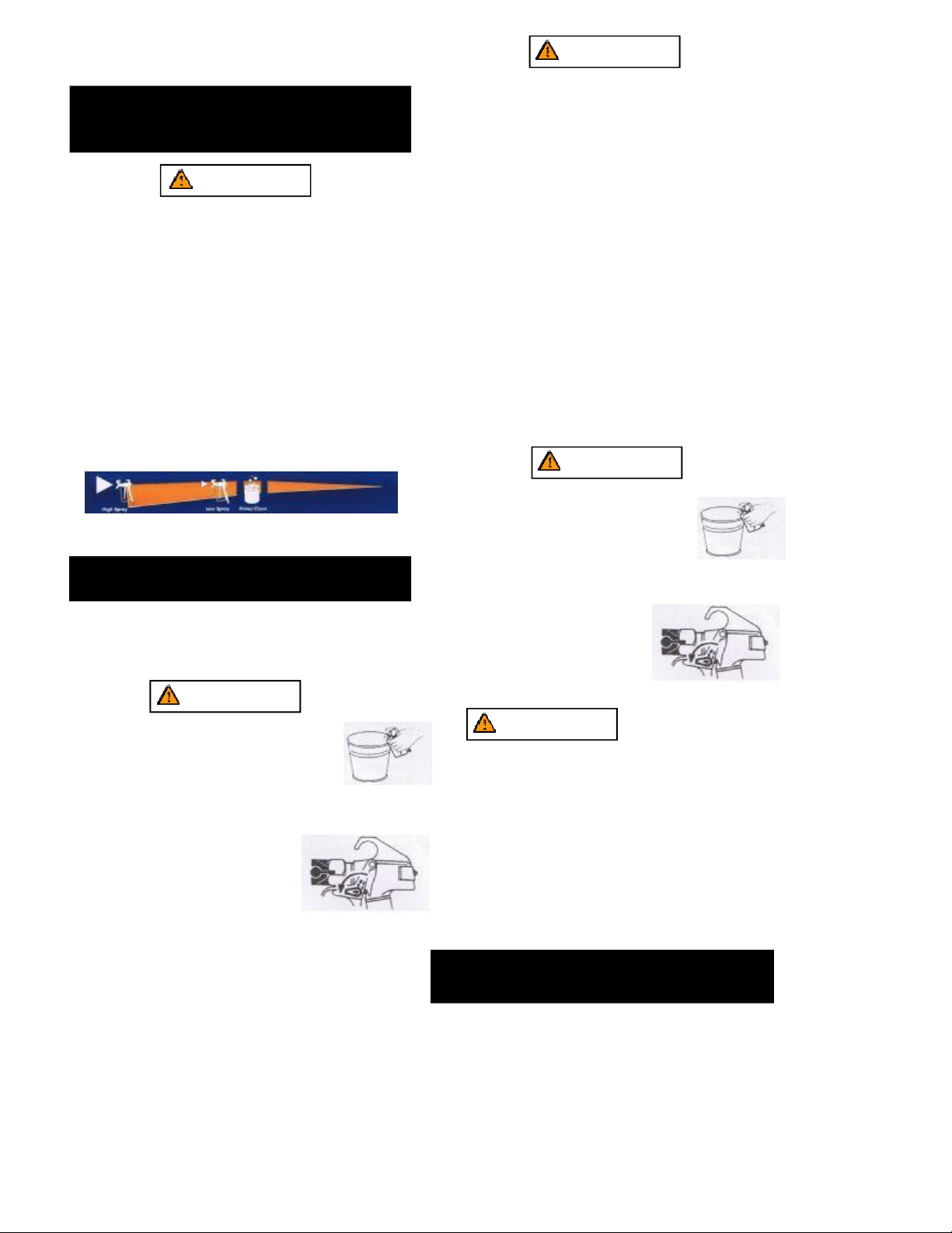
10.
Unlock the gun by turning the gun trigger lock to the
unlocked position.
WARNING
Ground the gun by holding it against the
edge of the metal container while flushing.
Failure to do so may lead to a static
electric discharge ,which may causea fire.
11.Trigger the gun into the metal waste
container until the old solvent is gone
and fresh solvent is coming out of the gun.
12.
Lock the gun by turnig the gun
t rigger lock to the locked position.
13.
Set down the gun and increase the
pressure by turning the pressure
control knob slowly clockwise into
the high pressure spray.
WARNING
Be sure to follow the pressure relief procedure when
shutting the unit down for any purpose ,including
servicing or adjusting any part of the spray system,
changing or cleaning apray tips,or preparing for cleanup.
Painting
1.Place the suction tube into a container of paint.
2.Place the return hose into a metal waste container.
3.Set the pressure to minimum by turning the pressure
control knob to the Min setting in the low pressure spray.
4.Move the PRIME/SPRAY valve down to the PRIME
position.
5.
Turn the unit on by moving the ON/OF switch to the ON
position.
6.
Allow the sprayer to run until paint is coming through the
return hose into the metal waste container.
7.
Turn the unit off by moving the ON/OFF switch to the OFF
position.
8.Remove the return hose from the waste container and
place it in its operating position above the container of paint
9.Move the PRIME/SPRAY valve up to the Spray position.
10.
Turn the unit on
11.
Unlock the gun by turning the gun trigger lock to the
unlocked position
WARNING
Ground the gun by holding it against the
edge of the metal container while flushing.
Failure to do so may lead toa static electronic
discharge, which may cause a fire. 12.Trigger
the gun in to the metal waste
container until all air and solvent is
flushed from the spray hose and paint is flowing freely
from the gun.
13.
Lock the gun by turning the gun
trigger lock to the locked position.
14.
Turn the unit off.
15.
Attach tip guard and tip to the gun
as instructed by the tip guard or tip
manuals . Trigger lock
in locked position
POSSIBLE INJECTION HAZARD. Do not spray without the
tip
guard in place .Never trigger the gun unless the tip is in
either the spray or the unclog position .Always engage
the
gun trigger lock before removing ,replacing or
cleaning tip.
16.Turn the unit on
17.
Increase the pressure by turning the pressure control
knob slowly clockwise toward the high pressure spray and
test the spray pattern on a piece of cardboard. Ajust
the pressure control knob until the spray from the gun is
completely atomized.Try to keep the pressure control
14.
Check the entire system for l ea k s .
ifleaks occur,follow the Pressure
Trigger lock
in locked position
knob at the lowest setting that maintains good
atomization.
Relief Procedure”in this manual before t ightening any f
ittings or hoses
15.
Follow the “Pressure Relief Procedure” in this manual
before changing from solvent to paint.
CAUTION
Note: Turning the pressure up higher then needed to
atomize the paint will cause premature tip wear
and additional overspray

6.
Off spray
Too thick
Start Pull
stroke trig ger
Release End
trigger
stroke
Pressure Relief Procedure
WARNING
Avoid arcing or holding the gun at an angle ,This will result in
an uneven finish.
Be sure to follow the pressure relief procedure when
shutting the unit down for any purpose ,including
servicing or adjusting any part of the spray system,
changing or cleaning spray tips, or preparing for clean up.
1.
Lock the gun by turning the gun
trigger lock to the lock position.
2.
Turn the unit off by moving the
ON/OFF switch to the OFF position.
3.Turn the pressure control knob
counterclockwise to its OFF position
4.Unlock the gun by turning the gun
Trigger lock
trigger lock to the unlocked position in locked position
5.Hold the metal part of the gun firm ly to
the side of a metal container to ground
the gun and avoida build up of static
electricity.
6.
Trigger the gun to remove any
pressure that may still be in the hose
7.
Lock the gun by turning the gun trigger lock to the locked
position.
8.
Move the PRIME/SPRAY valve down to the PRIME
position.
Spraying
Arcing Gun at angle
Proper lapping(overlap of spray pattern) is essential to an
even finish. Lap each stroke .If you are spraying horizontally,
aim at the bottom edge of the preceding stroke, so as to lap
the previous pattern by 50% .
WARNING
POSSIBLE INJECTION HAZARD. Do not spray without the
tip guard in place .Never trigger the gun unless the tip is
in either the spray or the unclog postion ,Always engage
the gun trigger lock before removing ,replacing ,or
cleaning tip.
Spraying Technique
The following techniques ,if followed,will assure professional
painting results.
Hold the gun perpendicular to the surface and always at equal
distance from the surface. Depending on the type of material,
surface ,or desired spray pattern,t he gun should be held ata
distance of 30 to 50 cm (12 to 14 inches)
Move the gun either across or up and down the surface ata
steady rate. Moving the gun at a consistant speed conserves
material and provides even coverage .The correct spraying speed
allows a full ,wet coat of paint to be applied without runs or sags.
Holding the gun closer to the surface deposits more paint on
the surface and produces a narrow spray patern.. Holding
the gun farther from the surface produces a thinner coat and
wide spray pattern .If runs ,sags ,or excessive paint occur,
change to a spray tip with a smaller orifice . If there is an
insufficient amount of paint on the surface or you desire to
spray faster ,a larger orifice tip should be selected.
Maintain uniform spray stroke action ,Spray alternately from
left
to right and right to left. Begin movement of the gun before
the
t rigger is pulled.
For corners and edges ,split the
center of the spray pattern on the
corner or edge and spray
vertically so that both adjoing
sections receive approximately
even amounts of paint.
When spraying with a shield ,hold it firmly against the surface.
Angle the spray gun slightly away from the shield and toward
the surface This will prevent paint from being forced underneath.
Shrubs next to housed should be tied back and covered witha
canvas cloth .The cloth should be removed as soon as possible.
our gun extensions are extremely helpful in these situations.
Nearby objects such as automobiles ,outdoor furniture,etc.
should be moved or covered whenever in the vicinity ofa
spray job.Be careful of any other surrounding objects that
could be damaged by overspray.
Overlap edges
1st 2st 3st 4st
5st
pass pass pass pass pass

7.
PRACTICE
1.
Be sure that the paint hose is free of kinds and clear of
objects with sharp cutting edges.
2.
Turn the pressure control knob counterclockwise to its to
its lowest setting.
3.
Turn the PRIME/SPRAY valve up to it s SPRAY position.
4.Turn the pressure control knob clockwise to its highest
setting. The paint hose should stiffen as paint begins to
flow through it.
5.
Unlock the gun trigger lock.
6.
Trigger the spray gun to bleed air out of the hose.
7.
When paint reaches the spray tip,spray a test area to
check the spray pattern.
Use the lowest pressure setting
necessary to get a good spray
pattern, If the pressure is set too
high,the spray pattern will be too
light. If the pressure is set too
low, tailing will appear or the
paint will spatter out in gobs
rather than ina fine spray.
Shutdown and Cleaning
1.
Pressure Control Knobs Settings
2.
Remove tip and guard assembly from gun and
place in flushing fluid.
3.
Lift suction tube and prime tube from paint pail
Let them drain into paint pail for a while.
4.
Separate prime tube (smaller)
from suction tube(larger)
5.
Place empty waste and
water or solvent pails
side by side.
6.
Place prime tube in waste
pail.
7.
Submerge suction tube in
water or flushing solvent.
8.
Turn pressure control knob to
the PRIME/CLEAN setting.
9.
Turn the power switch ON.
10.
Flush until approximately 1/3 of the flushing
fluid is emptied from the pail.
11.
Turn power switch OFF.
When storing the paint station for 16 hours or more,a
thorough cleaning is recommended:
1.shutdown paint sprayer
2.
thoroughly clean paint sprayer and station according
instruction;
3.
be sure that machine and tubes are clear any water or
fluid as these may freeze;
4.
Coil high pressure hose and store on back of tool with
hook and loop straps;
5.
Store filter spraying gun, and sprayer in plastic bag
and seal;

8.
Troubleshooting
Problem Cause Solution
The unit will not run 1.The unit is not plugged in
2.Tripped breaker
3.
The pressure is set too low(pressure
control knob set at minimum setting
does not supply power to unit)
4.
Faulty or loose wiring.
5.Excessive motor temperature.
6.ON/OFF switch is defective.
1.Plug the unit in
2.Reset the breaker.
3.
Turn the pressure control knob
clockwise t supply power to the unit
and increase the pressure setting.
4.
Inspect or take to a authorized service
center.
5.
Allow motor to cool.
6.
Replace the ON/OFF switch.
The unit will not prime.
1.The PRIM E/SPRAY valv e is in the
SPRAY position
2.Air leak in the position tube/suction set.
3.The siphon tube f ilter and /or inlet
screen is c logged.
4.The siphon tube/suction set is clogged.
1.
Rotate the PRIME/SPRAY valve
clockwise to the PRIME position.
2.
Check the siphon tube/suction set.
Connection and tighten or re-tape
the connection with Teflon tape.
3.
Remove the inlet screen and clean.
Rem ove the siphon tube/ suction set
and clearn.
The unit will not build or
maintain pressure
1.
The spray tip is worn.
2.the Spray tip is too large
3.
The pressure control knob is not set
properly
4.
The pump filter ,gun filter, or inlet
screen is clogged.
5.
Material flows form the return hose
when the PRIME/SPRAY valve is in
the SPRAY position.
6.
There is external fluid leak.
7.
Air leak in the siphon tube/suction
set.
8.
There is an internal fluid section leak
(packings are worn and/or dirty, valve
balls are worn).
9.
Worn valve seats.
10.
Motor power but fails to rotate.
1.
Replace the spray tip following the
instruction that came with the spray
gun.
2.
Replace the spray tip witha tip that
has a smaller orfice following the
instructions that came with the spray
gun.
3.
Turn the pressure control knob
clockwise to increase the pressure
setting.
4.
Remove the pump filters element
and clean. Remove the gun filter and
clean. Remove the inlet screen and
clean.
5.
Clean or replace the PRIME/SPRAY
valve.
6.
Check the siphon tube/suction set
connection and tighten or re-tape the
conncetion with Teflon Tape.
7.
Check for external leaks at all
connections. Tighten connections,
if necessary.
8.
Clean the valves and service the
fluid sectio n.
9.
Reverse or replance the valve seats.
10.Take unit to authorized service
center.
Fluid leakage at the upper
end of the fluid section.
1.
The upper packings are worn.
2.The piston rod is worn.
1.
Repack the pump following this
manual .
2.
Replace the piston rod.

9.
Troubleshooting
Problem Cause Solution
Excessive surge at the
spray gun.
1.Wrong type of airless spray hose.
2.The Spray tip worn or too large.
3.Excessive pressure.
1.
Replace hose with a minimum of 5m
(50 ”)X10 mm(1 /4 ”) ground textiled
braid airless paint spray hose.
2.
Replace the spray tip following the
instructions that came with the spray
gu
n.
3.
Rotate the pressure control knob
co unterclockwise to decrease spray
pressure.
Poor spray pattern. 1.The spray tip is too large for the
material being used.
2.
Incorrect pressure setting.
3.
The material being sprayed is too
viscous.
1.
Replace the spray tip with a new or
smaller spray tip fo lling the instructions
that came with the spray gun.
2.
Rotate the pressure control knob to
adjust the pressure for a proper spray
patter.
3.
Add solvent to the material according
to th e man ufac tu re s re co m me nda tio n s .
The unit lacks power. 1.The pressure adjustment is too low. 1.Rotate the pressure control knob
2.Improper voltage supply.
clockwise to increase the pressure
setting.
2.Connect the input voltage to the proper
voltage for the unit.
10 .

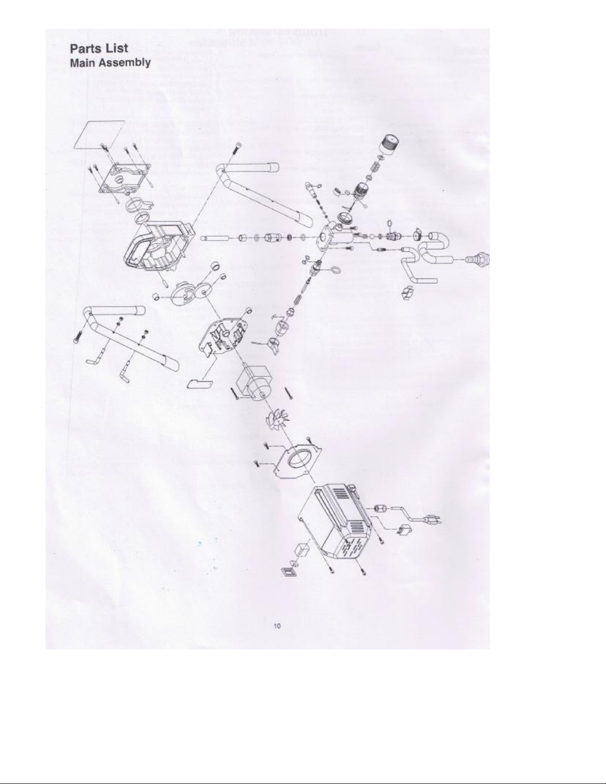
11 .
Motor Assembly
Motor Assembly
1.Motor.................................................. 1
9.ON/OFF switch................................1
2.Screw.................................... 2 10.Screw.................................................4
3.Motor fan............................... 1 11.Circuit breaker.................................1
4.Screw.................................... 4 12.Pin...................................................... 2
5.Gasket.................................. 1 13.Motor holder.....................................1
6.Motor cover labels.................. 1 14.Couper oring....................................1
7.Strain relief............................ 1 15.Screw.................................................4
8.Power cord............................ 1 16.Electric main board........................1

12 .
2
3
1
4
5
6
7
5
1
2
3
4
Gear Box Assembly
1.Cover laber........................................ 1
2.Screw................................................... 8
3.Front cover w/label......................... 1
4.Rod.......................................................1
5.Rod couper o-ring............................1
6.Pump housing...................................1
7.Crankshaft/gear assembly........... 1
Suction Set Assembly
Suction Set Assembly
1.Return tube assembly...................1
2.Retaining Clip..................................1
3.Siphon hose..................................... 1
4.Inlet screen...................................... 1
5.Clip......................................................1
8.Gear wrap..................................1
9.Wrap............................................1
10.2nd stage gear.............................. 1
11.Pin.....................................................1
12. Gear wrap.......................................2
13. Pin.................................................... 2
14. Gear wrap...................................... 1
Stand Assembly
Stand Assembly
1.Leg...................................................... 2
2.Screw................................................. 2
3.Cord wrap......................................... 2
4.Nut...................................................... 2
5.Mater washer...................................2
6.Drip cup............................................. 2
7.Drip cup2.......................................... 2
Gear Box Assembly
13 .
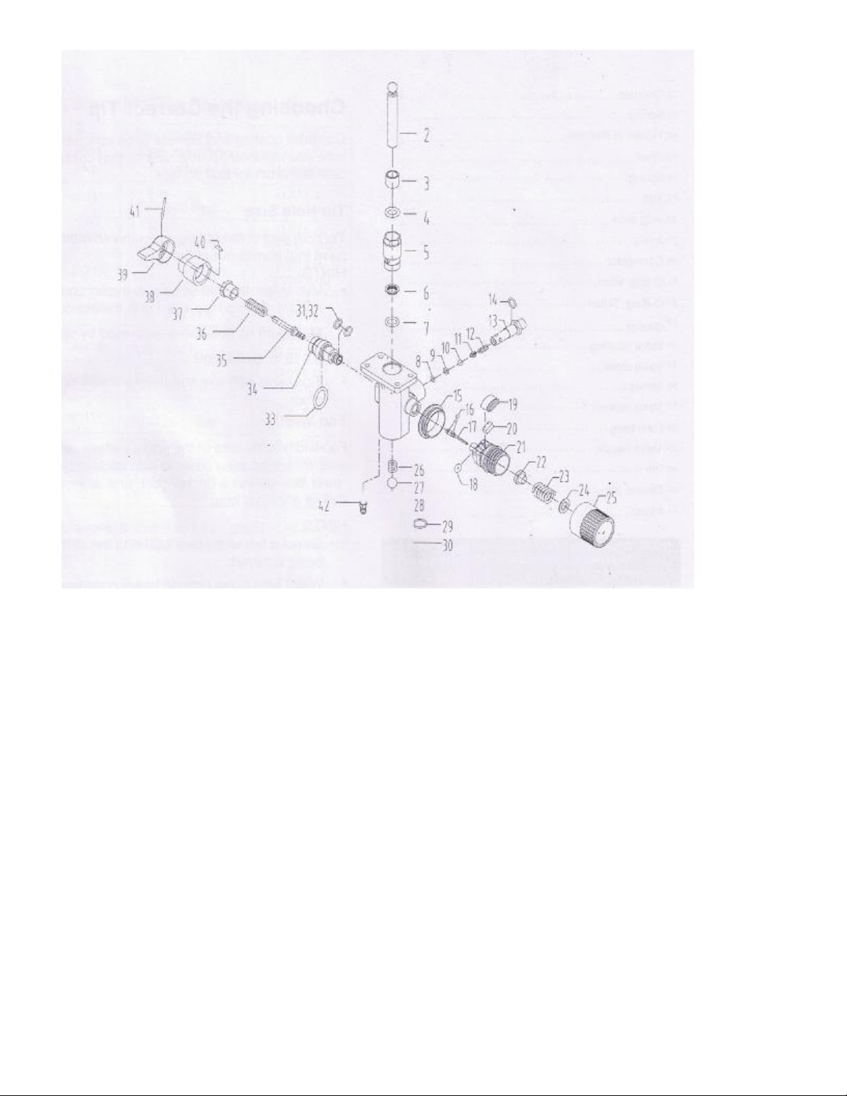
Fluid Section Assembly
Fluid Section Assembly
1.Fluid section................................... 1
2.Piston............................................... 1
3.Piston wrap A..................................1
4.O-ring................................................1
5.Piston wrap B................................. 1
6.O-ring................................................1
7.O-ring................................................1
8.Lvasher............................................ 1
9.Alloy slice........................................ 1
10.Ball.................................................... 1
11.................................................................Rocl 1
12.Spring.................................................1
13.Coupler.............................................. 1
14.O-ring................................................. 1
15.Cover.................................................. 1
16.O-ring................................................. 2
17.Pressure rocl....................................1
18.O-ring................................................. 1
19.Switch.................................................1
20.Plastic cover.....................................1
14 .
22. Coupler...........................................1
23. Spring............................................. 1
24. Holder H Needle.......................... 1
25. Shell................................................ 1
26. Spring............................................. 1
27. Ball.................................................. 1
28. Allg Slice........................................ 1
29. O-ring..............................................1
30. Connector......................................1
31. O-ring, Viton................................. 1
32. O-ring, Teflon................................1
33. Gasket............................................ 1
34. Valve Housing.............................. 1
35. Valve Stem.................................... 1
36. Spring............................................. 1
37. Valve Retainer..............................1
38. Cam base...................................... 1
39. Valve Handle................................ 1
40. Pin....................................................1
41. Groove Pin.................................... 1
42. Fitting..............................................1
Choosing The Correct Tip
Consider Coating and Surface to be Sprayed. Make sure
you use best tip hole size for that coating and best fan
width for that surface.
Tip Hole Size
Tip hole size controls flow rate the amount of paint
that comes out of the gun.
HINTS:
·
Use large tip hole size with thicker coatings
and smaller tip hole sizes with thinner coatings.
·
Maximum tip hole sizes supported by sprayer:
0.015 in. (0.38mm)
·
Tip wear with use and need periodic replace-ment.
Fan Width:
Fan width is the size of the spray pattern, which
determines the area covered with each stroke.
Narrower fans deliver a thicker coat, and wider fans
deliver a thinner coat.
HINTS:
·
Select a fan width best suited to the surface being
sprayed.
·
Wider fans allow provide better coverage on
broad, open surfaces.
·
Narrower fans provide better control on small,
confined surfaces.
Tip Selection
Selecting Tip Hole Size
Tips come in a variety of hole sizes for spraying a range
of fluids. Your sprayer includes an 0.015 in (0.38mm) tip
for use in most spraying applications. Use the following
table to determine the range of recommended tip hole
sizes for each fluid type. If you need a tip other than the
one supplied, see the Reversible tip Selection Chart
on page 15.
HINTS:
·
As you spray, the tip wears and enla rges, Starting
with a tip hole size sma ller than the maximum
w ill allow you to spray within the rated flow
capacity of the sprayer.
·
Maximum tip hole sizes supported by the sprayer.
0 .015 om (0.38mm)
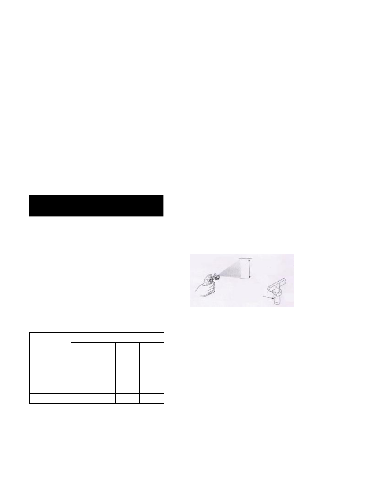
Understanding Tip Number
The Last Three digits of tip number (i.e.:221413)
Contain information about hole size and fan width on
surface when gun is held 12 in. (30.5cm) from surface
being sprayed.
First digit when doubled
= approximate
fan width 413 tip has
8-10 in.
Fan with
413 tip has
a 0.013 in
hole size
Last two digits= tip hole size in thousands of an inch
Tip Hole Size
Coatings
Stains
Enamels
Primers
In te rior Pa ints
Exterior Paints
0.011in.(0.28mm)
√
0.013in.(0.33mm)
√
√
√
√
0.015in.(0.38mm)
√
√
√
√
0.017in.(0.43mm)
√
√
√
0.019in.(0. 48mm)
√
NOTE: When Using “HOT” solvents, replace Viton O-
ring (item 32) with optional Teflon o-ring install
with o-ring tool

15.
Reversible Tip Selection Chart
Tip Part No:
Fan Width 12 in
(305 mm) from
surface
Hole Size
Alt311
6-8 in.
(152-203mm)
0.011 in.
(0.28mm)
Alt411
8-10 in.
(203-254mm)
0.011 in.
(0.28mm)
Alt313
6-8 in.
(152-203mm)
0.013 in.
(0.33mm)
Alt413
8-10 in.
(203-254mm)
0.013 in.
(0.33mm)
Alt415
8-10 in.
(203-254mm)
0.015 in.
(0.38mm)
Alt515
10-12 in.
(254-305mm)
0.015 in.
(0.38mm)
Alt417
8-10 in.
(203-254mm)
0.017 in.
(0.43mm)
Alt517
10-12 in.
(254-305mm)
0.017 in.
(0.43mm)
Alt519
12-14 in.
(305-356mm)
0.019 in.
(0.48mm)
Example: For an 8 to 10 in. (203 to 254mm) fan
width and 0.013 (0.38mm) hole size, order Part
No. alt413
Piston Lube
Specially Formulated to prevent materials
from adhering to the piston rod, which
become abrasive to the upper seals.
Pistonlube will break down any material
that may accumulate in the oil cup and
keep it from drying.
Part # Description
Alm-481.............4 ounce bottle
Miscellaneous
Part No. Description
Alm-012........Hose coupling, 1/4”x1/4”
Alm-397........High Pressure Fl. Gauge
Alm-171........Lubriplate, 14 ounce individual
Alm-172........Lubriplate, 6 lb. Can
Alm-1037......Electrostatic discharge
(ESD) wrist strap
Table of contents
Other Dino-Power Paint Sprayer manuals

Dino-Power
Dino-Power DP-6336iB User manual

Dino-Power
Dino-Power DP-X Series User manual

Dino-Power
Dino-Power DP-X Series User manual

Dino-Power
Dino-Power DP-X5 User manual

Dino-Power
Dino-Power DP-X6 User manual

Dino-Power
Dino-Power DP-6840iB User manual

Dino-Power
Dino-Power DP-X3 User manual

Dino-Power
Dino-Power Titan 440i User manual

Dino-Power
Dino-Power DP6391C User manual


