Dino-Power DP-X Series User manual

Operating Instruction
DP- X series
X20 X24 X28 X45 X52
Please read and keep this manual, Read carefully before attempting to assemble, install, operate or maintain the
product described. Protect yourself and others by observing all safety information. Failure to comply with instructions
could result in personal injury and/or property damage! Retain instruction for future reference.
WARNING
FIRE AND EXPLOSION HAZARD
Flammable fumes, such as solvent and paint fumes, in work area can ignite or explode. To help prevent
fire and explosion:
●Do not spray flammable or combustible materials near an open flame or sources of ignition such as
cigarettes, motors, and electrical equipment.
●Paint or solvent flowing through the equipment is able to result in static electricity. Static electricity
creates a risk of fire or explosion in the presence of paint or solvent fumes. All parts of the spray
system, including the pump, hose assembly, spray gun, and objects in and around the spray area shall
be properly grounded to protect against static discharge and sparks. Use DINO-POWER conductive or
grounded high-pressure airless paint sprayer hoses.
●Verify that all containers and collection systems are grounded to prevent static discharge.
●Connect to a grounded outlet and use grounded extensions cords. Do not use a 3-to-2 adapter.
●Do not use a paint or a solvent containing halogenated hydrocarbons.
●Keep spray area well-ventilated. Keep a good supply of fresh air moving through the area. Keep pump
assembly in a well ventilated area. Do not spray pump assembly.
●Do not smoke in the spray area.
●Do not operate light switches, engines, or similar spark producing products in the spray area.
●Keep area clean and free of paint or solvent containers, rags, and other flammable materials.
●Know the contents of the paints and solvents being sprayed. Read all Material Safety Data Sheets
(MSDS) and container labels provided with the paints and solvents. Follow the paint and solvents
Manufacturer's safety instructions.
●Fire extinguisher equipment shall be present and working
Sprayer generates sparks. When flammable liquid is used in or near the sprayer or for flushing or
●Keep sprayer at least 20 feet (6 m) away from explosive vapors.
ELECTRIC SHOCK HAZARD
This equipment must be grounded. Improper grounding, set up, or usage of the system can cause electric
shock.
●Turn off and disconnect power cord before servicing equipment.
●Use only grounded electrical outlets.
●Use only 3-wire extension cords.
●Ensure ground prongs are intact on power and extension cords.
●Do not expose to rain. Store indoors.
SKIN INJECTION HAZARD
High-pressure spray is able to inject toxins into the body and cause serious bodily injury. In the event that
injection occurs, get immediate surgical treatment.
●Do not aim the gun at, or spray any person or animal.
●Keep hands and other body parts away from the discharge. For example, do not try to stop leaks with
any part of the body.
●Always use the nozzle tip guard. Do not spray without nozzle tip guard in place.
●Use DP nozzle tips.
●Use caution when cleaning and changing nozzle tips. In the case where the nozzle tip clogs while
spraying, follow the Pressure Relief Procedure for turning off the unit and relieving the pressure
before removing the nozzle tip to clean.
●Do not leave the unit energized or under pressure while unattended. When the unit is not in use, turn
off the unit and follow the Pressure Relief Procedure for turning off the unit
●Check hoses and parts for signs of damage. Replace any damaged hoses or parts.
●This system is capable of producing 3630 psi. Use DP replacement parts or accessories that
are rated a minimum of 3000 psi

WARNING
PRESSURIZED ALUMINUM PARTS HAZARD
Use of fluids that are incompatible with aluminum in pressurized equipment can cause serious chemical
reaction and equipment rupture. Failure to follow this warning can result in death, serious injury, or
property damage.
●Do not use 1,1,1-trichloroethane, methylene chloride, other halogenated hydrocarbon solvents or
fluids containing such solvents.
● Many other fluids may contain chemicals that can react with aluminum. Contact your material supplier
for compatibility.
EQUIPMENT MISUSE HAZARD
Misuse can cause death or serious injury.
●Always wear appropriate gloves, eye protection, and a respirator or mask when painting.
●Do not operate or spray near children. Keep children away from equipment at all times.
●Do not overreach or stand on an unstable support. Keep effective footing and balance at all times.
●Stay alert and watch what you are doing.
●Do not leave the unit energized or under pressure while unattended. When the unit is not in use, turn
off the unit and follow the Pressure Relief Procedure for turning off the unit.
●Do not operate the unit when fatigued or under the influence of drugs or alcohol.
●Do not kink or over-bend the hose.
●Do not expose the hose to temperatures or to pressures in excess of those specified by us.
●Do not use the hose as a strength member to pull or lift the equipment.
MOVING PARTS HAZARD
Moving parts can pinch, cut or amputate fingers and other body parts.
●Keep clear of moving parts.
●Do not operate equipment with protective guards or covers removed.
●Pressurized equipment can start without warning. Before checking, moving, or servicing equipment,
follow the Pressure Relief Procedure and disconnect all power sources.
BURN HAZARD
Equipment surfaces can become very hot during operation. To avoid severe burns, do not touch
hot qui hot equipment. Wait until equipment has cooled completely.
TOXIC FLUID OR FUMES HAZARD
Toxic fluids or fumes can cause serious injury or death if splashed in the eyes or on skin, inhaled, or
swallowed.
●Please pay attention to know the specific hazards of the fluids before spraying.
●Store hazardous fluid in approved containers, and dispose of it according to applicable guidelines.
PERSONAL PROTECTIVE EQUIPMENT
You must wear appropriate protective equipment when operating, servicing, or when in the operating area
of the equipment to help protect you from serious injury, including eye injury, hearing loss, inhalation of
toxic fumes, and burns. This equipment includes but is not limited to:
●Protective eyewear, and hearing protection.
●Respirators, protective clothing, and gloves as recommended by the fluid and solvent manufacturer.

WARNING
Maintenance Tips:
1.There are two sides for the ball seat, both are chamfered, for one side worn, change to another side.
2.While changing the V-packings(both the upper and lower ones) for piston rod, please note that the convexity side shall be towards the piston rod,
then using rubber hammer to hit the flat side of the V-packings to fit the piston rod.
3. While fastening the screws for the pump block, please do not fasten one screw to maximum and then fasten the other one, the correct action is to
fasten one screw to 90% depth first and then fasten the other screw to maximum and later fasten the first screw to maximum.
4.There is one washing piece inside the pressure sensor, normally the washer won’t be broken, but it can not be left out.
5. After changing the upper V-packings, the nut shall be fully tightened by using a bench clamp.
6. Before starting up a new airless piston pump, please double check the two screws for the pump block and make sure that they are fully fastened.
Same checking after changing new V-packings.As the V-packings are made of high polymer material,after being stocked or used for some time, they
could somehow expand.
7. It’s critically important to turn on the PRIME VALVE before spraying or after changing the paint bucket, if air happens to enter into the piston pump
system and you forget turn on the PRIME VALVE before spraying, it will do big damage to the machine system itself, as the compression ratio for paint
coatings and for air are different.
8.The positive pole and negative pole for the motor can not be connected reversely via the carbon brush,if connected reversely, then the motor will turn
reversely,if the machine runs this way for some time, the motor be become demagnetized. (*For model X20 only)
9. If the V-packings are broken, then there will be paint coatings leakage, please change V-packings immediately, otherwise, the paint coatings may
enter into the gear box to damage the whole gear box.
10. While turning the pressure knob to adjust pressure,please do not turn the knob too hard,as the electric parts inside the knob could be damaged
due to too hard turning.
11.There is micro switch in every airless pump with mechanical pressure control system, and the fixing screw of the micro switch is set properly
before shipment, please do not try to change the position of the fixing screw, otherwise, the micro switch may not work properly.(For X20 model only)
12. One quick tip to identify if the ball seat is good or not, after turning the PRIME VALVE back to spraying position, please open the front cover, if the
connection rod stays on the upper position, then the ball inside the piston rod is somehow damaged, if the connection rod stays on the lower position,
then the ball seat is somehow damaged.
13. If the airless piston pump is not fully cleaned after spraying, the drywall coatings may stop the pressure sensor from working properly, so the airless
piston pump shall be fully cleaned after spraying.
14. If the fuse is burned due to over voltage, please check the capacitor first to see if it’s in good condition, if yes, then please further check the bridge
rectifier with a universal meter.
15.One quick tip to check the pressure control board for airless piston pumps with mechanical pressure control system, first step is to turn on the
PRIME VALVE, then stick to the micro switch with a screw driver, if the machine could stop, means no problem for the pressure control board.
16.If the airless pump is equipped with manifold filter, then the filter shall be often cleaned after spraying,once per day is recommended, or at least
once per week, if the filter is totally stuck by drywall coatings, then the electric board and pressure sensor could be burned, under this situation, fuse
could not protect the electronical board and pressure sensor.
17. As a reminder, for big airless piston pump with big flow rate(mainly refers to X45 and X52/X52L), please do not use short high pressure hose like
3m or 5m, as it might cause serious motor damage. Cleaning the machine, parts every time after finished the paint work.
18.Tips need to replace after 4000 – 5000 m2 depending on abrasiveness of paint.
19.The Piston rod/V-packing and sintered carbide ball need to replace after about 200 hours spraying, Especially when the pressure goes down,
or difficult to draw in paint.
20.For the permanent magnet DC motor, the carbon brush need to replace after 1500 hours, otherwise, the motor will be damaged.
21.Please check every parts had been screwed on the machine very tightly before using machine.
22.If the machine need to be storage over 10 days, Do run the machine with lubricating oil thoroughly, for rust protection or any stuck inside the
pump .(check the details in CLEAN UP)
23.For the maintenance of the fluid pump, do strictly in accordance with the instructions, and screw tightly.(check the details in Service)
24.Please read the manual or contact the distributor if any problems with the machine, DO NOT take the machine to pieces without professional staff.

Component Identification FOR X52L

1
Cart/ Hose with wrap rack
Carry machine and Stows paint hose. (DP637H)
2
Filter Housing
(Manifold filter inside**)
Manifold filter will reduce the tip clogs and ensure you nice finish.
3
Digital pressure display
(Under the cover)
X20 With Pressure Gauge Only
X24 X28 X45 X52 With digital pressure display
4
Pressure regulator
Adjust the pressure for different applications.
5
Prime/Spray valve.
●In PRIME position (pointing down) directs fluid to prime
tube.
●In SPRAY position (pointing parallel) directs pressurized
fluid to paint hose.
●Automatically relieves pressure system in overpressure
situations
6
Fluid pump
(piston rod&v-packing** inside)
Drains fluid in system during priming and pressure relief.
7
Suction tube
Draws fluid from paint pail into pump. (the tube must be screwed
tightly otherwise air enter inside, so the pressure can’t be reached
your desired high pressure.)
7
Suction hose*
The pics is X52L lower suction type, For X45/X52, it will be the
suction tube, and X20/24/28 will be the suction hose instead.
8
Suction filter
Suction filter reduce the tip clogs and ensure you nice finish.
9
Prime hose
10
Power Plugs
It will be suitable for countries.
11
Wheel
Easy for machine to stand/move on the ground.
12
Airless spray gun
Dispenses fluid.
13
High pressure hose
Transports high-pressure fluid from pump to spray gun.
(The parts marked with ** are easily worn parts.)
Technical Data
Operation
Item No.
X20
X24
X28
X45
X52
Pressure controlling
Mechanical
Electronic
Motor power
1100W
PMDC
1500W
Brushless Motor
1700W
Brushless Motor
2000W
Brushless Motor
2400W
Brushless Motor
Flow rate
2.0L/MIN
2.4L/MIN
2.8L/MIN
4.5L/MIN
5.2L/MIN
Max. tip size
0.021''
0.023''
0.025''
0.033''
0.035''
Max.Working
pressure
200bar/2900psi
Net/Gross weight
14.9/20.1kgs
15.1/20.3kgs
16.4/21.6kgs
45.5/61.2kgs
50.5/66.5kgs
Package
Carton box(49*42*53)
Woden Box(61*65*87)

Trigger Lock
Always engage the trigger lock when you stop spraying
to prevent the gun from being triggered accidentally by
hand or if dropped or bumped.
Pressure Relief Procedure
Follow this Pressure Relief Procedure whenever you
stop spraying and before cleaning, checking, servicing,
or transporting equipment.
1. Turn power switch OFF and unplug
power cord.
2. Turn Prime/Spray valve to PRIME
to relieve pressure.
3. Hold gun firmly to side of pail.
Trigger the gun to relieve
pressure.
4. Engage trigger lock.
NOTE: Leave Prime/Spray valve in the PRIME position
until you are ready to spray again.
If you suspect the spray tip or hose is clogged or that
pressure has not been fully relieved after following the
steps above, VERY SLOWLY loosen tip guard retaining
nut or hose end coupling to relieve pressure gradually,
then loosen completely. Clear hose or tip obstruction.
Read Unclogging Spray Tip instructions in the Sprayer
or Gun Operation manual.
Setup
1. Prepare the paint according to
the manufacturer’s recommendations
This is probably one of the most important steps
toward trouble-free spraying!
Remove any skin that may have formed on the top of
the paint. If necessary, thin the paint. Finally, strain
the paint through a fine nylon mesh filter bag
(available at most paint dealers) to remove particles
that could clog the spray tip
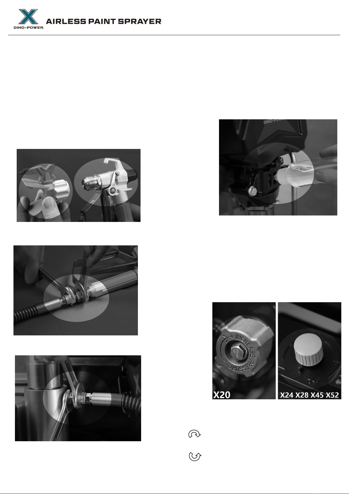
3. Unscrew tip and guard assembly from gun.
4. Uncoil hose and connect one end to gun. Use two
wrenches to tighten securely and tightly.
5. Connect other end of hose sprayer.
6. Oiling
Fill throat packing nut with lubricating oil(3~5 drops) to
prevent premature packing wear, Do this every time
when you spray.
7. Check the electrical service Be sure the electrical
outlet is properly grounded. Longer extension cords
may affect the sprayer performance. Use more spray
hose, not longer extension cords.
8.Plug in the sprayer. First be sure the ON/OFF
switch is OFF and the pressure control is turned
fully
counterclockwise. Plug the
sprayer
into a grounded
outlet that is at least 3 m away from the spray area to
reduce the chance of a spark igniting, spray vapors or
dust particles.
Pressure regulator valve
Clockwise: stronger / Higher pressure
Counter clockwise: weaker / Lower pressure

Startup
1. First be sure the ON/OFF switch is OFF.
2. Adjust Pressure Control counter clockwise to
lowest pressure.
3. Place the suction hose into the coating barrel.
4. Pull up the Prime/Spray Valve to Prime
position.
5. Plug sprayer in a grounded cable socket.
6. Switch ON the machine。
7. Turn the Pressure Control clockwise, till the
fluid is circulating in the prime tube
8. Turn power switch OFF.
9. Transfer suction tube to paint pail and
submerge suction tube in
paint.
10.Turn power switch ON.
11. When you see paint coming out of prime
tube:
(1). Point gun into waste pail.
(2). Unlock gun trigger lock.
(3). Pull and hold gun trigger.
(4). Turn Prime/Spray valve to SPRAY position.
12.Continue to trigger gun into waste pail until
you see only paint coming out of gun.
13. Release trigger. Engage trigger lock.
14.Transfer prime tube to paint pail and clip
prime tube to suction tube.

SPRAYING
SPRAYING TECHNIQUE
1. The key to a good paint job is an even coating over the entire surface. With spray painting, this is
done by using even strokes, with your arm moving at a constant speed and keeping the spray gun a
constant distance from the surface.
2. As much as possible, keep the spray gun at right angles to the surface. This means moving your
entire arm back and forth rather than just flexing your wrist.
30cm
3. Keep the spray gun perpendicular to the surface, otherwise one end of the pattern will be thicker
than the other.
Right way to spray
Approximately
10 to 12 Inches
Right way
Wrong
4. In most cases, the best spraying distance is 10 to 12 inches (25-30cm) between the spray tip and
the surface.
5. The spray gun should be triggered off at the end of each stroke and on again at the beginning of the
next. This avoids paint buildup at the end of the stroke which may result in runs and sags. Triggering
at the end of the stroke also saves paint and results in a better looking job. (See picture below)
Approximate
Work
10 to 12 Inches
E ven
Steady
Stroke
Start stroke End stroke
6. The
correct speed
for
moving
the gun will allow a full, wet coating to be
applied without runs or sags.
Lapping
each stroke about 40% over the
previous
stroke
produces
uniform paint thickness. Spraying in a uniform
pattern alternately from right to left and then left to right, provides a
professional finish. (See picture on the right)
One way to do this is to point the spray tip at the edge of the last stroke

before triggering the gun on.
7. When taking a short break from painting (up to 1 hr.), lock the spray gun trigger OFF, reduce pressure
to its minimum (zero) setting and set the unit to Prime position . Turn sprayer off and unplug. Refer
to Pressure Relief Procedure.
8. For interior corners, such as on a bookcase or inside a cabinet,
aim the gun toward the center of the corner to spray. By dividing the
spray pattern this way, the edges on both sides are sprayed evenly.
Install Tip & Guard on Spray Gun
1. Engage trigger lock.
2. Verify tip and guard parts are assembled in
order shown.
3. Use tip to align seat Tip must be pushed in
guard all the way into guard
4. Screw tip and guard assembly on
gun. Tighten retaining nut.
Gasket
Guard
Tip

Tip Selection
Selecting Tip Hole Size
Tips come in a variety of hole sizes for spraying a range of fluids. Your sprayer includes an 0.017 in
(0.43 mm) tip or maybe 0.019” (0.48mm) for use in most spraying applications. For narrow or smaller
surfaces(cabinet,fence,railings), pattern width of 6 inches is the best choice, it will provide sharper
definition and more control; For large surfaces(Ceilings/walls), a wider spray pattern width of 10 to 12
inches is your best choice to cover large areas more quickly.
Using a good-quality spray tip that is appropriately sized for your painting project is critical to achieving
good spraying results, the spray tip controls the amount of paint applied and the area the spray pattern
will cover. A range of tip sizes classified by both hole size and spray pattern width can be used, based
on 3 factors;
1;Coating/painting 2;Surface being sprayed 3;Sprayer's ability to support the tip hole size.
A key difference is sprayers is the maximum tip they can support. Choose your sprayer based on the
coating types you'll be spraying, and make sure the largest tip(hole size) you plan to use is within the
maximum tip size range the sprayer can support.
It is always best to have a machine with more capacity, Fox example, if you plan to use .017 tip
frequently, your sprayer's capacity should be one tip hole size larger(.019 tip), this allows for tip wear,
which causes the tip hose size to increase.
Choosing the Correct Tip
Consider coating and surface to be sprayed. Make sure you use best tip hole size for that coating and
best fan width for that surface.
Tip Hole Size
Tip hole size controls flow rate - the amount of paint that comes out of the gun.
HINTS:
• Use larger tip hole sizes with thicker coatings and smaller tip hole sizes with thinner coatings.
Fan Width Fan width is the size of the spray pattern, which determines the area covered with each
stroke. Narrower fans deliver a thicker coat, and wider fans deliver a thinner coat.

Understanding Tip Number
The last three digits of tip number contain information about
hole size and fan width on surface when gun is held 12 in.
(30.5 cm) from surface being sprayed.
Last two digits = tip hole size in thousands of an inch
Reversible Tip Selection Chart
Orifice Size
Fan Width - Inches
Flow Rate
Application
Filter
inch
4” – 6”
Fan
6” –
8” Fan
8” – 10”
Fan
10” – 12”
Fan
12” – 14”
Fan
gpm
L/min
0.011”
211
311
411
511
611
0.12
0.45
Stain or Lacquer
150mesh (red)
0.013”
213
313
413
513
613
0.18
0.68
0.015”
215
315
415
515
615
0.24
0.91
Oil Base Paint
100mesh (yellow)
0.017”
217
317
417
517
617
0.31
1.17
Latex Paint /
Acrylic / Enamel
100mesh
0.019”
219
319
419
519
619
0.38
1.44
60mesh (white)
0.021”
321
421
521
621
0.47
1.78
0.023”
323
423
523
623
0.57
2.16
Heavy latex
60mesh (white)
0.025”
325
425
525
625
0.67
2.54
0.027”
427
527
627
0.77
2.91
0.029”
329
429
529
629
0.90
3.41
Elastomeric /
Blockfiller /
Primer /
30mesh (green)
0.031”
331
431
531
631
1.03
3.90
0.033”
333
433
533
633
1.17
4.43
0.035”
335
535
1.31
4.98
0.043”
243
343
443
543
643
1.98
7.51
Important things to know about tip wear
It's important to replace a tip when it becomes worn, this ensures you''ll have a precise spray pattern,
maximum productivity and a quality finish. When tip wears, the hole (orifice) size increases and spray
pattern width decreases.
Tip life varies by coating, Extend tip life by spraying at the lowest
pressure that breaks up (atomizes)the coating into a complete
spray pattern.
Recommend tip replacement Latex: After 4000~5000 ㎡

CLEAN UP
As with all spray equipment, your sprayer must be cleaned properly or it will not operate properly.
Clogged are the most common causes of problems. If followed, these guidelines will insure trouble
free performance from your sprayer.
1. Do pressure relief procedure.
Remove siphon tube set from paint and place in
flushing fluid.
Note: Use water for water base paint and mineral spirits
for oil base paint
2. Turn power On, turn
prime/spray valve up to
close drain valve.
3. Increase the pressure to about to 1/2
maximum take the trigger safety OFF, trigger
gun until flushing fluid appears.
3. Move the gun to waste pail, hold gun against
pail, trigger gun to throughly flush system,
release trigger and put trigger safety ON.
4. Turn prime valve down to open drain valve
and allow flushing fluid to circulate for 15
seconds to clean drain tube.
5. Raise siphon tube above flushing fluid and
run sprayer for 15 or 30 seconds to drain fluid.

7. Turn up prime valve up to close drain valve,
Trigger gun into flushing pail to purge fluid from
hose, Turn Power OFF.
8. Turn prime valve down to open drain valve,
Unplug sprayer.
9. Remove filters from gun and sprayer, if
installed. Clean and inspect, install filters.
10. If flushing with water, flush again with
mineral spirits, or pump armor, to leave a
protective coating to prevent freezing or
corrosion.
11.If the machine will be storage for over 10 days,
after you cleaned the machine thoroughly,
please take off the suction tube, hose&gun, and
pour about 10ml WHITE lubricating oil into the
fluid pump, Then switch on the machine and let it
keep running (PRIME POSITION) for 5
seconds(once you can see the oil in the prime
tube), This will prevent the wet parts inside being
stuck, corrosive or rusted.
12. Wipe sprayer, hose and gun with a rag
soaked in water or mineral spirits.

Troubleshooting
Problem
Cause
Solution
Power switch is on and
sprayer is plugged in, but
motor does not run, and
pump does not cycle.
Pressure is set at
zero pressure.
Turn pressure control knob clockwise
to increase pressure setting.
Motor or control is damaged.
Please contact with your supplier or
DPAIRLESS directly.
Electric outlet is not providing
power.
• Try a different outlet or plug in
something that you know is working
to test outlet.
• Reset building circuit breaker or
replace fuse.
Extension cord is damaged.
Replace extension cord.
Sprayer electric cord
is damaged.
Check for broken insulation or wires.
Replace electric cord if damaged.
Paint and/or water is frozen or
hardened in pump.
Unplug sprayer from outlet. If frozen
do NOT try to start sprayer until it is
completely thawed or you may
damage the motor, control board
and/or drivetrain.
Make sure power switch is OFF.
Place sprayer in a warm area for
several hours. Then plug in power
cord and turn sprayer ON. Slowly
increase pressure setting to see if
motor will start.
If paint is hardened in sprayer, pump
packings, valves, drivetrain or
pressure switch may need to be
replaced. Please contact with your
supplier or contact with DP-AIRLESS
directly.

Problem
Cause
Solution
Sprayer starts up but does
not draw in paint.
Unit will not prime or has lost
prime
Replace prime Unit
No paint. Suction tube
not totally immersed in paint
Immerse suction tube in paint
Suction set filter clogged.
Clean filter.
Suction tube loose at inlet valve
Clean connection and tighten
Inlet valve is leaking
Clean inlet valve. Be sure the ball
seat is not nicked or worn and that
ball seats well, Reassemble valve.
Pump packing are worn
Replace pump packings.
Piston rod worn or damaged.
Clean or replace
Pump cycles but does not
build up pressure.
Pump is not primed.
Prime pump.
Inlet screen is clogged .
Clean debris off inlet screen and
make sure suction tube is immersed
in fluid.
Suction tube is not immersed in
paint.
Make sure suction tube is immersed
in paint.
Suction tube is leaking.
Tighten suction tube connection.
Inspect for cracks or vacuum leaks. If
cracked or damaged, replace suction
tube.
Prime/Spray Valve is worn or
obstructed with debris.
Clean the valve or replace a new one.
Pump cycles, but paint only
dribbles or spurts when
spray gun is triggered.
Pressure is set too low.
Slowly turn Pressure Control Knob
clockwise to increase pressure
setting which will turn motor on to
build pressure.
O-ring in pump is worn or
damaged
Replace O-rings
Inlet valve ball is packed with
material
Clean inlet valve,
Spray tip is clogged
Unclog spray tip
Fluid filter is clogged.
Clean or replace fluid filter
Spray gun fluid filter is clogged.
Clean or replace gun fluid filter,
Spray tip is too large or worn.
Replace tip.

Problem
Cause
Solution
Sprayer draws up paint but
drops away when gun is
opened
Worn spray tip
Replace with new tip.
Suction set filter clogged
Clean filter.
Gun or spray tip filter plugged.
Clean or replace filter. Keep extra
filters on hand
Paint too heavy or coarse.
Thin or strain paint
Worn V-packing
assembly.
Replace
Inlet valve worn or damaged.
Replace valve
Tip assembly leaks
Assembled incorrectly
Check assembly.
Worn seal.
Replace seal.
Spray gun won't spray
Spray tip, gun filter or
tip clogged
Clean spray tip
filter plugged
Clean or replace gun or filter.
Spray tip in Clean position
Put tip in Spray position
Paint tailing.
Pressure is set too low.
Increase pressure
Gun, tip, or suction
filter plugged.
Clean filters
Suction tube loose
Tighten suction tube fitting
Tip worn.
Replace tip
Paint too thick
Thin paint
Thermal overload tripped
Motor over heated.
Allow to cool 15 to 30 min.
Paint build up on motor.
Clean paint from motor.
Unit sitting in hot sun.
Move to a shady location
No display,
sprayer operates.
Display is damaged or had bad
connection.
Check connection, replace display
Display error code E02
Communication failure
Check the signal line
between pressure sensor and PCB
Display error code E03
Pressure sensor failure
check the pressure sensor
if poor contact or damaged
Display error code E04
Motor and
PCB communication failure
Or mechanical fault
Check the signal line between motor
and PCB or if mechanical
components stuck

Display error code E06
IPM alarm
Display error code E07
High pressure in
cleaning mode
Reduce the pressure when cleaning
Display error code E08
Low line voltage
Check the power supply
Paint leaks down outside of
pump..
Pump packings are worn
Replace pump packings.
Fan pattern varies
dramatically while spraying.
OR Sprayer does not turn
on promptly when resuming
spraying.
Pressure control switch is
worn and causing
excessive pressure variation.
Please contact with your supplier or
DP-AIRLESS.

Parts List
X20 Motor&Pressure control assembly
No.
Serial No.
Description
Qty
No.
Serial No.
Description
Qty
1
X20301
Carbon Brush
1
15
X20515
Stem
1
2
X20302
Baffle
1
16
X20516
Spring
1
3
X20303
Carbon Brush
1
17
X20517
Pressure Regulating Knob
1
4
X20304
Brush Holder
2
18
X20518
Wire
1
5
X20305
Washer
1
19
X20519
Circuit Board
1
6
X20506
Capacitor
1
20
X20520
Bridge
1
7
X20507
Screw
2
21
X20521
Screw
1
8
X20508
Wire
1
22
X20322
Rotor
1
9
X20509
Pressure Regulator Housing
1
23
X20323
Bearing
1
10
X20510
Wire
1
24
X20324
Washer
2
11
X20511
Connector
1
25
X20325
Long Screw
2
12
X20512
Switch
1
26
X20326
Fan
1
13
X20613
Power Cord
1
27
X20327
Screw
1
14
X20614
Plastic Cover
1
28
X20328
Stator
1
Other manuals for DP-X Series
1
This manual suits for next models
5
Table of contents
Other Dino-Power Paint Sprayer manuals

Dino-Power
Dino-Power DP-X Series User manual

Dino-Power
Dino-Power DP-X5 User manual

Dino-Power
Dino-Power DP-6336iB User manual

Dino-Power
Dino-Power Titan 440i User manual

Dino-Power
Dino-Power DP6388B Operation instructions

Dino-Power
Dino-Power DP-6840iB User manual

Dino-Power
Dino-Power DP6391C User manual

Dino-Power
Dino-Power DP-X6 User manual

Dino-Power
Dino-Power DP-X3 User manual


