Dino-Power Titan 440i User manual

Operationmanual for Airlesspaint
sprayer
High PressureElectric Airless paint sprayerTitan 440i model
intelligentseries
Remark:thisguidemanualisthesamewithmodel DP-6389 ,the contentinclude :the
operationofequipment,cleaning,maintenance,andrepair,besuretopre-operational,read
themanualcarefullybeforeyou usethismachine.

2
1.warningand precautions
SafetyPrecautions
Thismanualcontainsinformation thatmust beread andunderstoodbeforeusing
theairlesssprayer equipment.Whenyoucometoan areathat hasone ofthefollowing
symbols,payparticularattentionand makecertaintoheedthe safeguard.
WARNING
Thissymbolindicatesapotentialhazardthatmaycauseseriousinjuryorloss of life.
Importantsafetyinformation will follow.
CAUTION
Thissymbolindicatesapotentialhazardtoyouortotheequipment.Important information
thattellshowtoprevent
damage totheequipmentorhowtoavoidcausesofminorinjurieswill follow.
NOTE: Notesgiveimportantinformation whichshouldbegiven specialattention.
WARNING
HAZARD:Injectioninjury Ahighpressurefluidstreamproducedbythisequipmentcan
piercethe
skinandunderlyingtissues,leading toseriousinjuryandpossibleamputation.See a
physician immediately.
DONOTTREATANINJECTIONINJURYAS A SIMPLECUT!Injectioncan leadto
amputation.See aphysicianimmediately.
Themaximumoperating rangeof thesprayeris3200PSI/221BARfluidpressure.
PREVENTION:
•NEVERaimtheairless spraygun at anypartof the body.
•NEVERallowanypartofthe bodytotouchthefluidstream.DONOTallowbodytotouch
aleakinthefluidhose.
•NEVERputhandinfrontofthegun.Gloveswillnot provideprotectionagainstan
injection injury.
•ALWAYSlockguntrigger,shutpumpoff, and releaseallpressurebeforeservicing,
cleaningtiporguard,changing
tip,orleavingunattended.Pressurewill not bereleasedbyturningoff themotor. The
PRIME/SPRAYvalvehandle
mustbeturned toPRIMEtorelievethe pressure. RefertothePRESSURERELIEF
PRESSUREdescribedinthepumpmanual.
•ALWAYSkeepairlesstipguard inplacewhilespraying.Thetipguardprovidessome
protection butismainlyawarningdevice.
•ALWAYSremovethe spraytipbeforeflushingorcleaning thesystem.
•Painthosecandevelopleaksfromwear, kinkingandabuse.Aleakcan injectmaterial
intothe skin.Inspect the hosebeforeeachuse.
•NEVERuseaspraygun withoutaworking triggerlockandtriggerguardinplace.
•Allaccessoriesmust beratedatorabove3200PSI/221BAR.Thisincludesspraytips,
guns,extensions,andhose.

3
NOTETOPHYSICIAN:
Injectionintothe skinisatraumaticinjury.Itisimportant totreattheinjuryassoonas
possible.DONOTdelaytreatment toresearchtoxicity.Toxicityisaconcernwithsome
coatingsinjected directlyintothebloodstream.Consultationwithaplasticsurgeonor
reconstructivehandsurgeonmaybe advisable.
HAZARD: EXPLOSIONANDFIRE Solventandpaint
fumescanexplodeorignite.Severeinjuryand/orpropertydamagecan occur.
PREVENTION:
•Provide extensiveexhaust andfreshairintroductiontokeepthe airwithinthesprayarea
freefromaccumulationof flammablevapors.
•Avoidall ignitionsourcessuchasstaticelectricitysparks,electricalappliances, flames,
pilotlights,hotobjects,andsparksfromconnecting anddisconnecting powercordsor
working light switches.
•Donotsmokeinsprayarea.
•Fireextinguishermustbe presentandingood working order.
•Placepumpatleast20feet(6.1m)fromthesprayobjectinawellventilatedarea(add
morehoseifnecessary).
Flammablevaporsareoften heavierthan air.Floorareamustbeextremelywellventilated.
Thepumpcontainsarcingpartsthat emitsparksandcanignitevapors.
•Theequipment andobjectsinandaroundthe sprayareamust beproperlygroundedto
preventstaticsparks.
•Useonlyconductiveorgroundedhigh-pressurefluidhose.Gunmustbegrounded
through hoseconnections.
•Powercordmustbe connected toagroundedcircuit.
•Alwaysflushunitintoseparatemetalcontainer,atlowpumppressure,withspraytip
removed. Holdgun firmlyagainstsideof containertogroundcontainerandpreventstatic
sparks.
•Followmaterialandsolventmanufacturer’swarningsandinstructions.
•Useextremecautionwhen usingmaterialswithaflashpoint below70°F(21°C).
Flashpointisthe temperatureatwhichafluidcanproduceenoughvaporstoignite.
•Plasticcancausestaticsparks. Neverhang plastictoenclosesprayarea.Donot use
plasticdrop clothswhensprayingflammablematerials.
•Uselowestpossiblepressuretoflushequipment.
GASENGINE (WHEREAPPLICABLE)
Always placesprayeroutsideofstructureinfreshair.Keepall solventsawayfromengine
exhaust.Neverfill fueltankwitharunningorhotengine. Hotsurfacecanignitespilledfuel.
Always attachgroundwirefrompumptoagrounded object.Refertoengineowner’s
manualforcompletesafetyinformation.
HAZARD: EXPLOSIONHAZARD DUE TOINCOMPATIBLE
MATERIALS willcausesevereinjuryorpropertydamage.
PREVENTION:
•Donotusematerialscontainingbleachorchlorine.
•Donotusehalogenated hydrocarbonsolventssuchasbleach, mildewcide,methylene
chlorideand1,1,1 trichloroethane. Theyarenotcompatiblewithaluminum.

4
•Contactyourcoatingsupplierabout the compatibilityofmaterialwithaluminum.
HAZARD:HAZARDOUSVAPORS Paints, solvents, insecticides,andothermaterials
canbeharmfulifinhaledorcomeincontactwithbody. Vaporscancauseseverenausea,
fainting,orpoisoning.
PREVENTION:
•Usearespiratorormaskif vaporscanbe inhaled. Readallinstructionssuppliedwiththe
masktobesureitwill provide thenecessaryprotection.
•Wearprotectiveeyewear.
•Wearprotectiveclothingasrequiredbycoatingmanufacturer.
HAZARD:GENERAL Can causesevereinjuryorpropertydamage.
PREVENTION:
•Readallinstructionsandsafetyprecautionsbeforeoperatingequipment.
•Followallappropriatelocal,state,andnationalcodesgoverning ventilation, fire
prevention,and operation.
•TheUnitedStatesGovernmentSafetyStandardshavebeenadoptedunderthe
OccupationalSafetyandHealthAct(OSHA). Thesestandards,particularlypart1910of
theGeneralStandardsandpart1926 oftheConstruction Standards,shouldbeconsulted.
•Useonlymanufacturerauthorizedparts.Userassumesallrisksand liabilitieswhen
using partsthatdonot meettheminimumspecificationsandsafetydevicesofthepump
manufacturer.
•Beforeeachuse,checkallhosesforcuts, leaks,abrasion orbulgingof cover.Checkfor
damage ormovementofcouplings.Immediatelyreplacehoseif anyof thoseconditions
exist. Neverrepairapainthose. Replacewithagroundedhigh-pressurehose.
•Allhoses,swivels,guns, and accessoriesmust bepressurerated atorabove
3200PSI/221BAR.
•Donotsprayoutdoorson windydays.
•Wearclothingtokeep paintoffskinand hair.
•Alwaysunplugcordfromoutletbeforeworking onequipment.
GroundingInstructions
Thisproductmust begrounded.Intheeventofanelectricalshortcircuit,grounding
reducestheriskofelectricshockbyprovidingan escapewirefortheelectriccurrent. This
productisequippedwithacordhavingagrounding wirewithan
appropriategroundingplug. Theplugmustbepluggedintoanoutlet thatisproperly
installedandgroundedinaccordancewithalllocalcodesandordinances.
DANGER —Improperinstallationofthegroundingplug canresultinariskofelectric
shock.If repairorreplacementofthecordorplugisnecessary,donotconnectthegreen
groundingwiretoeitherflatbladeterminal.Thewirewithinsulation
havingagreenoutersurfacewithorwithoutyellowstripesisthe groundingwireand must
beconnectedtothegroundingpin.
Check withaqualified electrician orservicemanifthegroundinginstructionsarenot
completelyunderstood,orif youareindoubtastowhethertheproductisproperly
grounded.Donot modifytheplugprovided. Ifthe plugwill notfit the
outlet, havetheproperoutletinstalledbyaqualifiedelectrician.
GroundedOutlet

5
GroundingPin
Coverforgroundedoutletbox
CAUTION
Useonlya3-wireextensioncordthat hasa3-bladegrounding pluganda3-slot
receptaclethatwill accept theplugon theproduct. Makesureyourextensioncordisin
goodcondition.Whenusingan extensioncord, besuretouseone heavyenough tocarry
thecurrent yourproductwilldraw.Anundersizedcordwill causeadropinline voltage
resultinginlossofpowerandoverheating.
2.NameofequipmentComponentsandfeatures
introduction
A
Motor DC motor 220V 50HZ single-phase
B ICS intelligentPressurecontroller.
Pressuresensorsand equipmenthavesuggestedthat
the statusofthe equipmentfuction
C SuctionComponents
UseWithinthe upperandlowerComponentsforthe
twovalvecoatingwillbeaddedafterthesupercharger
andexhaust
D Pressureadjustment Knob /Button
ControlthecoatingPressureexport
E On/off switch Controlanequipment operationorstop
6
F Pumpfilters The percolationgetsintothe coating inthe equipment
G ReturnValvereturntoverticaldirectionforthestateopen,the
horizontaldirectionforsprayingstate(close)
H Coating painting outlet LinkCoatingtubeand manometerPosition
I Suctiontube Willbefrombucketsinthepaintinhalationequipment
J Paint returntube Returntothestatepaintorsolventoutflowfromhere
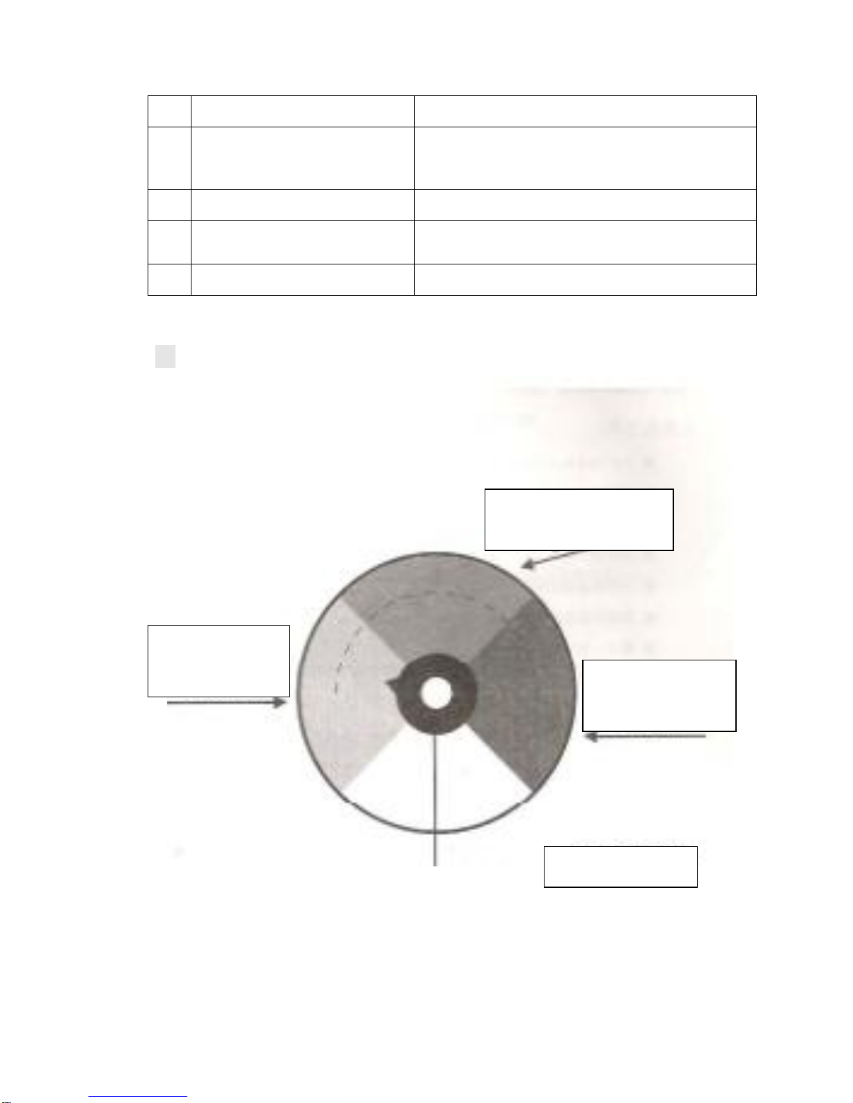
Thepressurecontrolbutton operating Constructions
Nopressurearea(yello
w) indicatethatclose
state
Middlepressurearea(green)
indicatethatmiddlepressure
High pressure(red)
indicatethathigh
pressure
pressurecontrolbutton

7
3.operation
I preparebeforeswitching on.
1. preparetool:
i.5-inch,6-inchall withinahexagonalwrench.
ii.Cross screw4
iii.14-17、17-19ofadouble-headed wrench
iv.ablenderorastirringrod
v.antivirusmaskand aset ofoveralls
vi.abrush
vii.somerags
viii.amultimeter
ix.30-meter 2.5MM²powerlineextension
x.apowerregulator
2. preparetorysteps:
⑴assurancesuctiontubeand therefluxtubelinktheright ofpositionandscrewedtightly
⑵firstlycontecton thecoatingmanometerexit ,then 15meterhighpresurenylon coating
ofpressuregaugesconnected totheexportterminaland screwedtightly(pressuregauge
inthefirstcoating totheexit)
⑶havigtousetwowrenchwillbe nohigh-pressureairlessspraygunconnectedtothe
headand anotherscrewedtightly.
⑷deteminepressuremanometercontrolbuttonssetinthe displaymorethan 150
locations
(5)multimeterdeteminedbymeasureing powersupplyis220-250(equipmentallowing
fluctutationofvoltage)voltsofvoltage.
(6)equipmentwillbedisplayed atthedistanceofatleast7.5metersinconstructionplace
dryregion.

8
3. the initialuseofnewequipment:
the newequipment of thefactorycontainaprotectiveeffect lubricants,so
theinitialuseofnewequipmentneedtojointhecleanwateroffewsoapto
takeintoclean ,theflollowingstep iscleaning:
⑴addtosuctiontube containingalittlesoapywaterinthebuckets
⑵addtothewastewillbereturnedinthepaintbarrels\buckets.
(3)returnvalvewillbeinstalledintheverticaldirection .
(4)openequipment powerswitch..
(5)letsoapywatertoperationequipmentintheequipmentwithinthecircle,untilthe
outflowofcleanwaterfromthereturntube .
II preparetivebeforespraying:
beforespraying,theymustfirstdeterminespraypainthasbeengood
andhavebeen initially harmonicfiltering ,otherwiseundesirablecoating
equipmentwill increaswearandreducethe lifespanofequipment.in
addition,eachtimebeforespraying,thepaintmustbeused bydelicated
diluent(suchasspraying latexpaintwatercanbeused)toallowequipment
tocycleagainandagainspraying,thefollowing is operationsteps:
⑴add suctiontube will be fittedwithspecialdiluentorcleaninthe bucket.
⑵add tothewastewill be returnedinpaintbucket.
⑶Pressurecontrolbuttonswillbeset inthemiddle(yellowareas)butthebottom
ofthelocationofequipment functioning.
⑷returnvalvewillbeinstalledinthe verticaldirection.
⑸Powerequipment opened.
⑹equipmenttooperation 15to30secondsuntiltheclean diluentfromtheoutflow
ofreturn
⑺shut thepowersswitch.
⑻settherefluxvalvetothepositionoflevel.
⑼turnonthepowerswitch
9
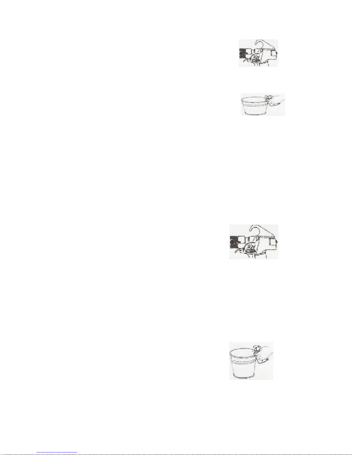
⑽openspraygun insurance.
⑾paintgunmouthtodiscardthepaintwall inside thebucket,deductionunderthe
trigger,andthesprayguntopaintthe originaloldsolventremoved ,untiltheclean
upofthenewsolventexclusion.(astheabovechart)
⑿closesprayguninsurance(astherightchart)
⒀slowlypressurecontrolbuttonswillbesetinthehigh pressure(greenareas)
position.
⒁carefullycheckthe equipmentineveryareawhetherthereisadripphenomenon
andifso,pleasefollowthe “pressurereliefsteps”forpressurerelief,then drip
screwedtightlyontothesite.
2.spraying:
⑴addsuction pipe will berequiredforsprayingpaint bucket .
⑵addtothewastewillbereturnedinpaint buckets.
⑶pressurecontrolbuttonwill besetinthe middle(yellowarea)butthebottomof the
locationofequipmentfunctioning.
⑷returnvalvewillbeinstalledintheverticalposition .
⑸startequipment
⑹equipmenttobeginoperationuntiltheoutflowofthepaint fromtherefluxtube .
⑺shut\closeequipment power.
⑻movethe refluxtubetothecoating buckets
⑼returnvalvewillbesetinthe horizontalposition.
⑽Turnonthepowerswitch.
⑾opensprayguninsurance.
⑿thedeductionunderthetriggerdevicesfromtheresidualsolventuntilatgunpoint
fromtheemitofpaint(asthe rightchart)
⒀closesprayguninsurance.(astherightchart)
⒁shutthe powerswitch.
⒂fittedjacketsandnozzleand nozzlescrewed tightly.
⒃turnonthepowerswitch.
⒄slowlypressurecontrolbuttonswillbeset tomiddleorhigh pressure(the yellow
orgreenarea),inthefirsttrialelsewherespray,paintandgraduallyincreasethe
pressureuntilthe coatingcompletelyfogging up ,you canbeginconstruction.

10
3.pressurereliefsteps
⑴closesprayguninsurance(astheright chart)
⑵shutthe powerswitch.
⑶pressurecontrolbuttonswillbe setonplacewithoutpressure(black areas)
potision.
⑷opensprayguninsuranceanda180-degree reversal.
⑸paintbarrelsofthegunsatthewall,thedeductionunderthe trigger,the
equipmentand piping inthe pressuresrelease.
⑹closesprayguninsurance.(astherightchart)
⑺returnvalvewillbesetinthe verticalposition ,allintheequipmentmaybe
remnantsfromthepressure.
III day-to-daymaintenancemeasures.
⑴beforeeachspraying,checkcompliancewithelectricity.
⑵Beforeeachspraying,wemustadd sealoilintothemouthdropPSL5-6.
⑶aftereachspraying,theequipmentmust be thoroughlycleanedandparts.
⑷aftereachspraying,pleashigh-pressurehosecoiledtoprevent damagetotie.
⑸Iflong-termstoragedoesnotwork, shouldbe usedtoprotectthebodyfluid(blue
bottle),abottleofprotectionagainstthebucket ofwatertodilutethe protectionof
theequipment, cycle,theroleistoprotecttheequipment,sparepartsfrom
corrosion,andthefinalLeta little lubricationequipmentinhalationsolution, andadd
thePSL.
warning
inanyequipment cleaning,repairand maintenance
orbeforethemiddleof thebreak,andyoumuststep
inaccordancewiththeventingpressurerelief.
11
IV.sprayingskills
1.Caution shouldbetakenwhen operatingspraygun,high-pressurehosesandoperatorof
physicalcoordinationbetweenthe two,theoperatorstandingatthe feetsprayingdistance
slightlyoverShoulderWidth,ahigh-pressurepipeintheirhands,high-pressurepipewill
benot stretched too tight,help toSpraywhentheshift easier.
2.Theright handgraspsspraygun, notproperbutton uptomoveatriggerwithindexfinger
andmiddlefingertootightly.
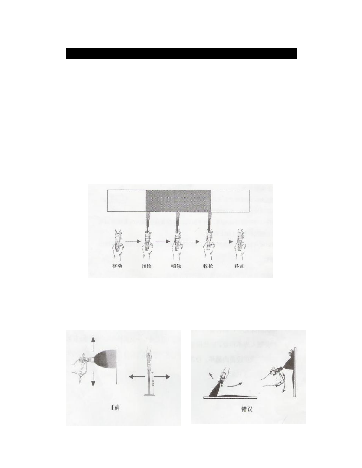
3.Eachspraygunshouldbeintheprocess ofmovinganddynamicrelaxation trigger
deduction,sotheworkpiecesurfacecan beavoided excessiveaccumulationof paintflow
andtheformationofpegging.(asforchart)
4.Spraygunshould beverticalwiththeworkpiecesurface,the surfacefrom25to30cm
distance,whenmobile,maintain the samespeed,notslowsuddenlyjumpedupquickly,and
wherepossible,tomaintain parallel,inordertoavoid surfacecoatingsorunevenflowpegged.
(asforchart)
12
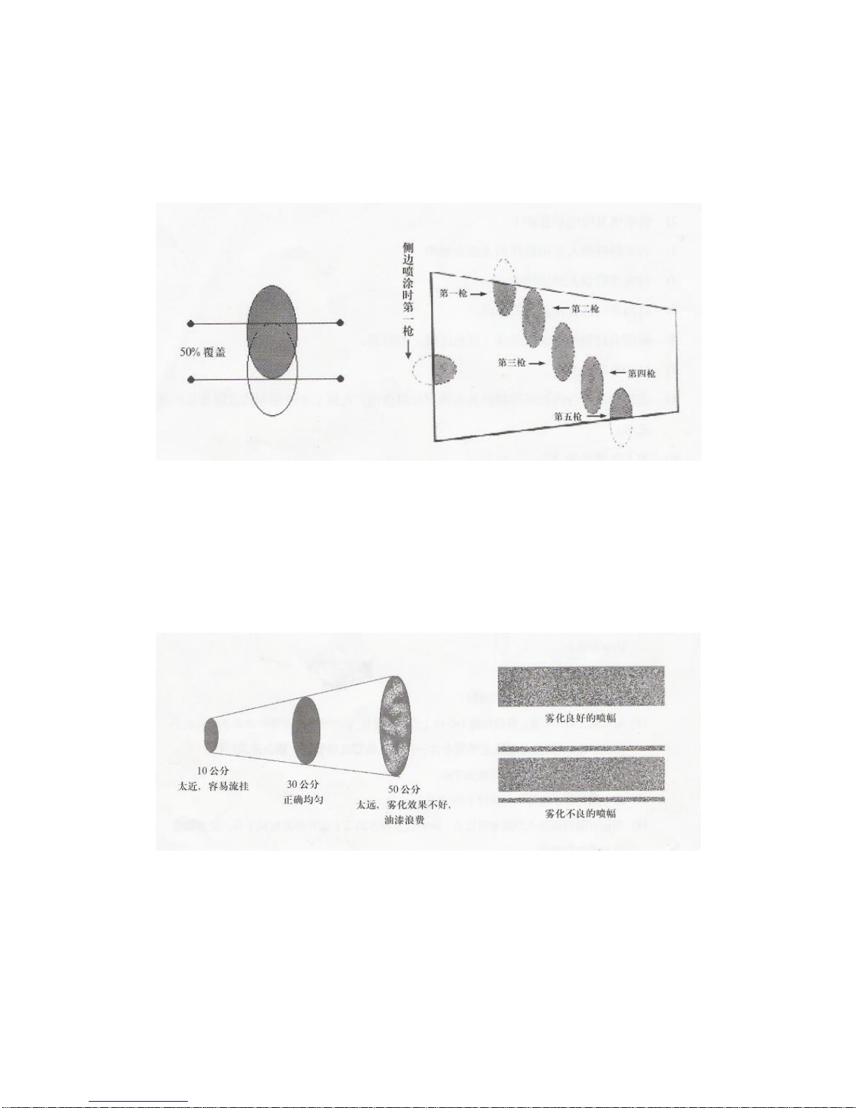
5.Inorderto obtaincomplete and uniformcoating,weareheretoadvise you when thespray gun should
be coveredbefore eachshot50percent, thatis,50per centof the lap,so the entireworksurface coating
line Uniform
(asforchart).
6. Before Membersof thesprayingoperation,tofind the bestinthe vicinityof wood ornon-construction
of aworkpieceonthetestspraying, sprayingtoadjustthe distanceandspraypressure,asshown
below, the correct spraying distance and the pressure toachieve perfectionSpraying effect.

1
3
V.cleans
⑴Firstaccordingtothe"pressurereliefsteps"toejectthepressureandcoatinginside
equipment.
⑵Nozzlesandnozzlejacket willbe unloaded.
⑶Addsuctionpipe willbeputinto clearwaterbucket or the appropriationdilution.
⑷Put therefluxtube into Paint wastebarrels.
⑸Returnvalvewillbeinstalled intheverticaldirection
⑹Pressurecontrolbuttonswill beset inthewashingposition
(theredarea)
⑺Turnonthepowerswitch.
⑻Inthesolventrecyclingequipment, paintresiduesdischarged untilcleanwateror
solvent fromtheoutflowof refluxtube.
⑼Shutthepowerswitch.
⑽Returnvalvewill besetinthehorizontalpositionandopenspraygun insurance.
⑾turnon the powerswitch
⑿Buttonningupthetrigger makes solvents orclear waterflushtoremaincoating insidehigh
pressuretube and spray gun,until solvents or clearwater are jet fromthemuzzl
⒀shutspray gun insurance.(astherightchart)
⒁Loadednozzle jacketandopenspraygun insurance.
⒂Nozzlewillbe reversed180degrees, sustained gundeduction1~ 2seconds(cleaning
nozzles),nozzlesand nozzle jacketunloaded andcleaned withbrushes.(cleaning
nozzleattention toputintoawhite-washersandnozzlesBlock, pleasedonotlost.)
⒃Unloadingequipment andspraygunsonthe filternetthenclean
⒄Unload suctiontube filterandclean .
⒅Withpilesofragssolventorcleanwaterequipment,high-pressurehosesandspray
gun allthecomponentsoftheappearancewipecleanuntilasurfaceAdhesion without
coating.
⒆Equipmentintheinfusionfluidvalve5-6PSLdrop ofaclosedyellowliquid.
⒇Equipment will be storedindry,cleanandwell-ventilated places

14
VI.maintenance
Beforemaintenance,youmustdeterminethe faultoftheequipment,otherwise,
the equipmentsunnecessaryequipmentaccessibilitywillseriouslyaffectthefunction and
greatlyreducetheservicelifeofequipments.
Alsoin themaintenanceofthe equipment,be suretobe dressedin overallsand
maintenancetoolstandards,andadequatelightingandchooseawell-ventilatedplacetocarry
outrepairsandprepareabucket ofclean
solvent, aswell asthe equipmentat thevariouscomponentswithin the washing.
1. Filterreplacementsteps
●pumpfilter:
⑴Using thewrenchwillpumpabodyfilteroutershelltounload
⑵Clockwisedirectiontorevolvingpump
filterslightly.
⑶Carefullycheckedfilteranet andseal ringcompletely,
when it'snecessary,Carryoncleaningorreplacement.
⑷Anti-clockwisedirectiontoreplaceor
cleanthe filter.
⑸Installedtofilterscrewedtightlyontotheoutshell.
●gunbodyfilter:
⑴Opensprayguninsurance.
⑵Unload pikestaffwiththewrench
⑶Togentlyclockwiserotationdirectionof
thefilterunderthegunbody.
⑷Willbecleanfiltersinstalledanti-clockwiseback of thegunbody.
⑸Indeterminingthecorrectlocationgripsring,it willbe grips
Screwedtightlyontotheback andloaded.
⑹Close spraygun insurance(astherightchart).
15
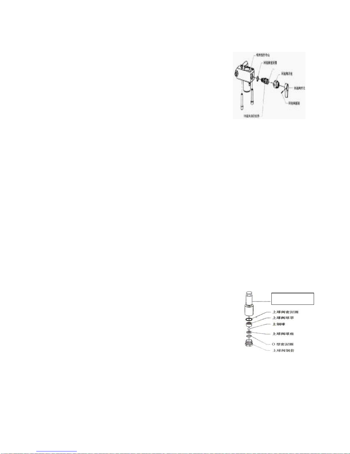
2.Return valvemaintenancesteps
⑴Removereturnvalveswitchonthebolt.
⑵Unloadingreturnvalveswitchandswitchback seat.
⑶Bywrenchreturnvalvecomponentsunloadedthimble.
⑷Determine returnvalvegasketsintherightposition.
⑸Willbeanewreturnvalveinstalledoncomponents
screwedtightlyonto.
⑹Inreturnvalveswitchappliedtoasmalllubricantsand install.
⑺thimble. toreturnvalvecomponentsexposedswitchatthefront.
⑻Loadedwithswitchesandplugswillbe fixedwithswitchthimble.
3. Suctioncomponentrepairsteps
●atthebeginningofanysuctioncomponentofmaintenanceorrepair,itmustbethe
suction tubeandthereturntubeofequipmentunloading,andthenformaintenanceor
repair,thefollowingisthesteps:
⑴Cross screwdriverswill be usedundertheplatecylinderon thetwoaspectsoffixedand
rotaryscrewunloaded.
⑵rotaryandremoved.the returntubewithwrench
⑶Suctiontubering will beremoved , andsuction tubeoutfromthebelowcylinder.
⑷when drawingOut,theequipmentwillbeslightlytilted tothefutureoperationmore
convenient.
●BallValverepairsteps:all thecomponentsin theequipment,ballvalvesarethe most
vulnerable tonotclean and cleaningequipmentcannotbeplugged sothatthe normal
operationsitting position,sothe ballvalvecleaningand maintenanceisveryimportant,
thefollowingisthe ball valvedisassemblysteps:
⑴10-inchwrenchestogetherwiththewholeoftheballvalveand cylinderbushingsremoved
⑵Carefullycheckingandcleaningpartsofthis
in everyarea, if damaged, Must be replaced.
⑶Bywrenchafterspin ontheballvalveand
plungerrodremoved.
⑷Similarlycheck ontheballvalvewhetherplugor
wear, ifnecessary,cleanedOrreplacement.
⑸Indeterminingupperand lowerball valvecomponentscleanintact, withthesameball valve
willbeinstalledin ordertosuction components.
Note:absorptionisnotnormallyundertheball valveplug,ifthe ball valveundernormal
ballvalveonanotherdemolition, cleaning ballvalvecan onlyusecleansoft cottoncloth,and
wipeprohibitedtheuseofahardobject.
Plungerrob

16
●Suctionringcomponent replacement
⑴Inaccordancewiththe"ballvalvemaintenancesteps"
tounload theupperand lowerballvalve.
⑵Suctioncomponentwillbebelowthetwo-position
rotarynutremoved.
⑶Suctiontubecomponentswillbe slightlyshellandpulled
downsothattheshell about1.5cm fromthe equipment.
⑷Fromthefield inthesuction componentswillbe
introducedslowlyshell straightPlungerrodtothe
crankshaft andconnectingrodofthebottomof the
T-mount separation.
⑸Willbedownfromthe suctionplungerrod componentsfromtheshell launched.
⑹Suctioncomponentsshellwillbefixedonthenutsandlocatorremoved.⑺Willbe removed
within theshellonthethree ring .
⑻CleaningsuctioncomponentsshellwillbeinstalledwithnewwhiteringbackShell.
(Installationoftheorderanddirectionof makingreferencetothefollowing diagram).
Note:newsuctionequipmentmanufacturedcomponentsfortheblackring,and
suction component repairpacketringiswhite.
上部密封圈安装方向 下部密封圈安装方向
O型密封圈在安装时应将上部 O型密封圈在安装时应将下部
密封圈上的凸起面朝下 密封圈上的凸起面朝上
⑼Carefullycheckplungerrod, ifwearorscratches,needimmediatereplacement.
⑽Willbeloaded back ontheballvalveandplungerrodscrewedtightly.
Note:thislinkcan be usedon thecrankshaft T-type cardwhichbescrewedtightlyonto
the pistonrodfixation.
⑾Willbe embeddedin theupperlocatornutfixed,andfixedequipmenttosuction nutshell
components, the manpowertohandrotation.

17
⑿Indeterminingsealsring and locatorinstalledinthecorrectposition,thepiston rodwillbe
componentsfromthe suction casingfromthe bottomtobottom-upequipment,andrubber
hammertoknockplungerrod gentlyintothesuction components, until theplungerrodintothe
correctposition.
Note:plungerrodandallcomponentsrequiredin theload applied toasmall lubricants.
⒀fixednut screwedtightlywiththewrench
⒁Willbe installedsuction componentsembedded in thetopofthe bottomofthecrankshaft
connectingrod T-typeCardnotch.
⒂Will be installed suctioncomponentspushedupuntil the suctionequipmentand
componentsshellcasing notseamless.
⒃thebottomshell ofsuctionComponentswill befittedwithscrewsand screwedtightly.
⒄Will beinstalledunderthe blockcomponentstogetherwiththe ballvalveandcylinder
componentsinstalled tosuctionscrewedtightlyontothe shell.
⒅Suctionpipe willbeinstalledundertheblockand backwithafixedclasp.
⒆Willbereturntubebacktotheinstallation of suctionscrewedtightlyontothecomponents.
⒇Accordingtothe"operation steps"toactivatetheequipmentand inspectionequipment
availabilitydrip.
(
21
)
According tothe "operationsteps"toactivatetheequipmentandinspection equipment
availabilitydrip.
Note:Evenifthereisaseal ringdamage,butalsotheneed toreplacetheentire
maintenancepackage AccessoriesGroup.
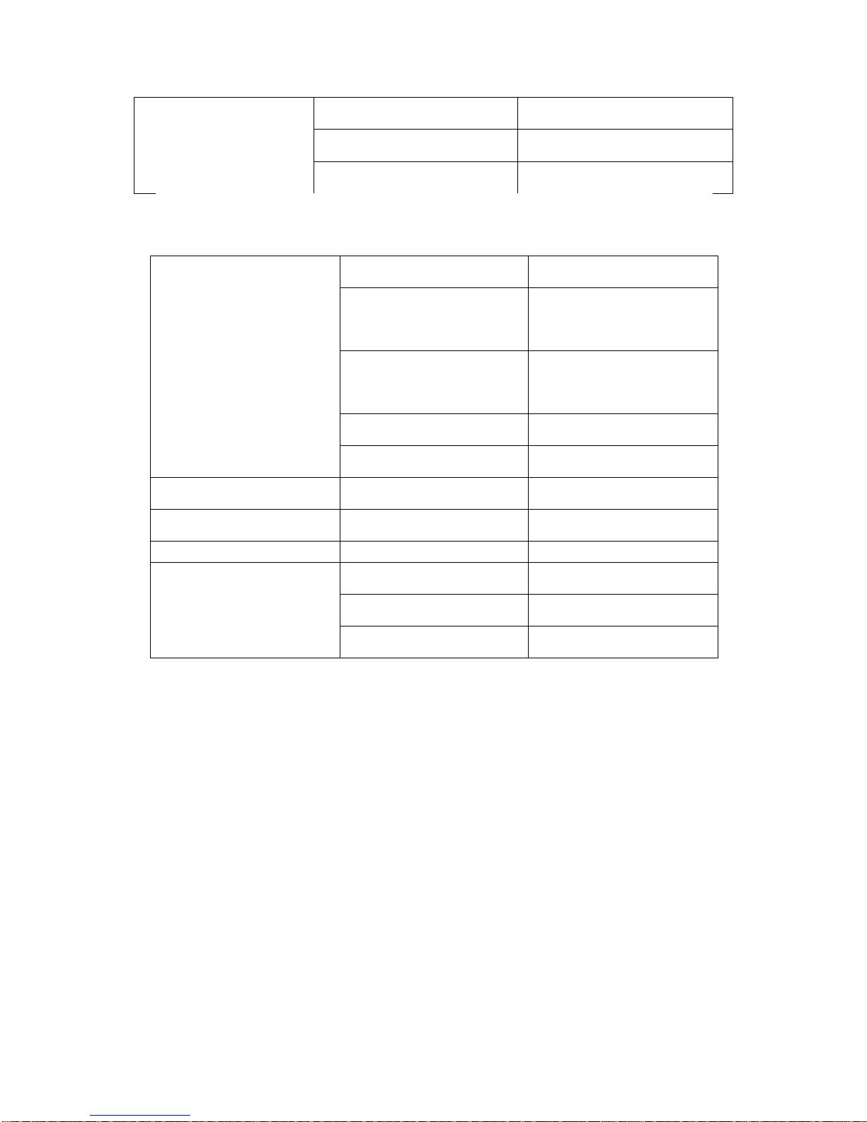
7.Frequentlyaskedquestionsand troubleshooting
equipmentFrequentlyAskedQuestions
1.Power circuit ornotto poorcontact 1. Checkcircuit
2.Set toolow pressure 2. Set toolow pressure
3 electricalBrush damaged or bad contact. 3.electrialBrushreplacementor
inspection.
4.Motorburn 4. Replacement motor
5.Switchdamage 5. Replacementswitch
Motordoesnot
operate
6.Equipmentoverload, powerswitchup 6. pressedto the powerswitch
warning
Refrain in theinstallation,useballvalveplungerrod ortube
clamp-vices, thiswill causethe piston-cylinderdamagecaused
bytheleakingofphenomenon.

18
1.airinthe tube 1.Checksuctiontubes and opento
returnvalves
Nosuctionequipment
2.Inadequateequipment pressure 2. increase pressure
1.Nopaintsupply 1. Inspection
2 Suction tube filter plug. 2.Cleaning or replacementfilters
3.Gun body filter plug 3.Cleaning or replacementfilters
fluxingistoosmallor
no fluxing
4.highcoating viscosity 4. Diluted paint
1.Equipment leakage 1. 1.Screwedtightlyonto the
equipmentcomponents
2.Suctiontubeleak 2.Screwed tightly onto thesuction
tube and check
3.the lower ball valve plug 3. Cleaning the lower theballvalve
4.Cylinderseals under wear 4. Sealring replacement.
5.Ballvalve wear orplug 5. Cleaning or replacing the ballvalve
6.BallValve seatwear 6.ball valve seatreplacement
Equipment is
impossibleto
maintainpressure
7.Returnvalve wear 7.Returnvalve replacement
1.set Returnvalve too low 1. increase pressure
2.Filter plug 2.Cleaning or replacementfilters
Pressureshortage
3.nozzle Excessive or wear 3. Replacementnozzles
1.Incorrectpaint\coating pipe1.Replacementof therightpaintpipe
2.nozzle too muchor wear 2. Replacementnozzles
Spraygunabnormal
vibration
3.Toomuch pressure 3. Reduce pressure
The paintfromthefuel
leakage
1.Cylinderseals ring under wear 1. Replacementsealring
2.、spraygun Frequentlyasked questions
1.airinthe Equipment 1. checking
2.spray gun withdirty 2. cleanpray gun
The spray gun has coating to
leak
3.spray gun sealring wear 3. Sealringreplacement
1.spray needle sealring wear 1.sprayneedleorseal ring
replacement
spraygun cannotstop
discharging
2.spray gun withdirty 2. Cleaning spraygun
19
1 Supplyfree paint. 1. checking
2.nozzle Or filter plug 2. Cleaning spraygunand sealring
spraygunnotexpecting
3.spray needle wear 3. sprayneedlereplacement
3. SprayFrequentlyaskedquestions
1.Spraying underpressure 1. increased Coatingspressure
2.Paintcannot be totally
atomized
2. Replacesmaller nozzle
3.Paint enoughvelocity 3.cleaningspraygunand
equipment sealring
4.Paint high viscosity 4. Reduce the viscosityof paint
Trailing spray sitesare
phenomena
5.nozzleWear 5. Replacementnozzles
Unevenspray sites 1.Nozzleclogging or wear 1. Replacementnozzles
Middle thick 1.there aregaps for Nozzle 1. Replacementnozzles
Spray rate distortions side 1.Nozzleclogging or wear 1. Replacing or cleaningnozzle
1.Suctiontube leakage 1.checkand Screwed tightly
2.Incorrectuseofpaint 2. The correctuse ofpaint
Spray ratejumps(Mandrax
largest Mandraxsmall)
3.nozzletoomuch orWear 3. Replacementnozzles
20
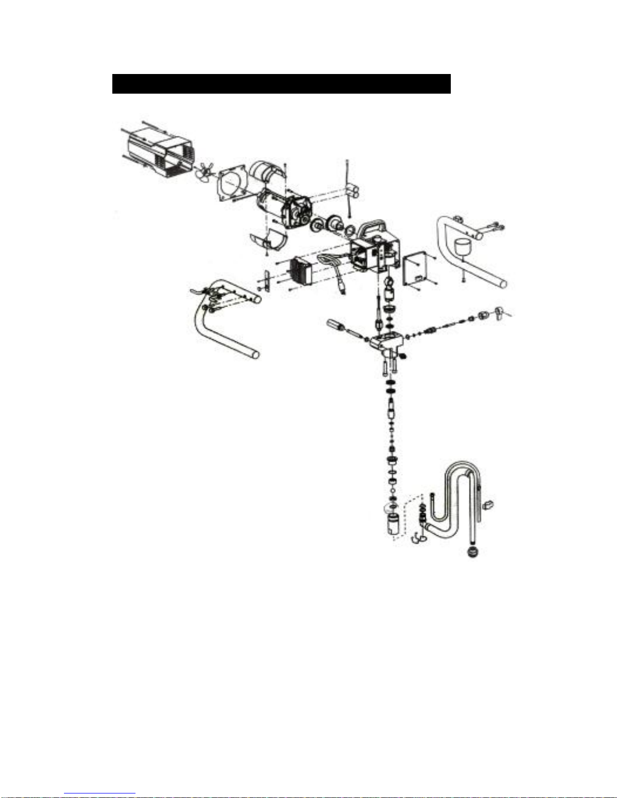
8、explodeddrawing and partslist
Suction componentdecomposition map
Table of contents
Other Dino-Power Paint Sprayer manuals

Dino-Power
Dino-Power DP-X Series User manual

Dino-Power
Dino-Power DP-X6 User manual

Dino-Power
Dino-Power DP-6840iB User manual

Dino-Power
Dino-Power DP6391C User manual

Dino-Power
Dino-Power DP-6336iB User manual

Dino-Power
Dino-Power DP-X5 User manual

Dino-Power
Dino-Power DP-X3 User manual

Dino-Power
Dino-Power DP-X Series User manual

Dino-Power
Dino-Power DP6388B Operation instructions


