3
there is a high electrical risk, thereby providing maximum op-
erator safety.
-
Arc Force to select the best dynamic characteristics of the
welding arc.
-
Hot Start to improve ignition with particularly difficult elec-
trodes.
- Anti-sticking function to avoid the electrodes sticking.
Usage limits (IEC 60974-1)
The use of a welder is typically discontinuous, in that it is made up
of effective work periods (welding) and rest periods (for the posi-
tioning of parts, the replacement of wire and underflushing opera-
tions etc. This welder is dimensioned to supply a I2max nominal
current in complete safety for a period of work of X% of the total us-
age time. The regulations in force establish the total usage time to
be 10 minutes. The work cycle is considered to be X% of this period
of time. If the permitted work cycle time is exceeded, an overheat
cut-off occurs to protect the components around the welder from
dangerous overheating.Activation of thermal protection is signaled
by “t° C” flashing on control panel display (for further information
see the control panel manual).After several minutes the overheat
cut-off rearms automatically and the welder is ready for use again.
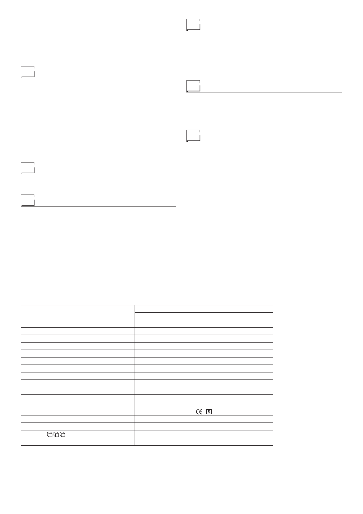
Technical data
The general technical data of the system are summarized in ta-
ble 1.
How to lift up the welding power source
The weld welding power source has a strong handle all in one
with the frame, used for transporting the welding power source
manually only.
NOTE: These hoisting and transportation devices conform to Eu-
ropean standards. Do not use other hoisting and transportation
systems.
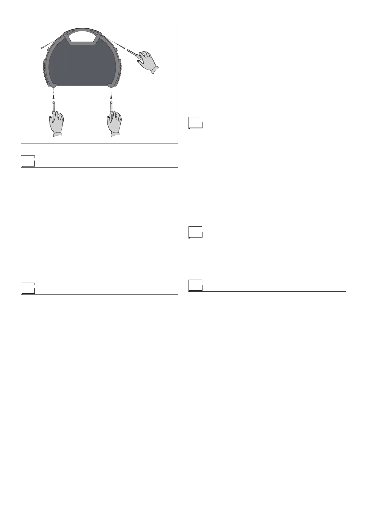
Open the packaging
Upon receiving the system:
•
Remove the welding generator and all relevant accessories-
components from their packaging.
• Check that the weld welding power source is in good condition,
if not report any problems immediately to the seller-distributor.
•
Make sure all ventilation grilles are open and that no foreign bod-
ies are blocking the air circulation.
Serial number
The welding power source’s serial number is shown on the unit’s
data plate.
The serial number provides the key to tracing the production lot
applicable to the product. The serial number may be essential with
ordering spare parts or planning maintenance.
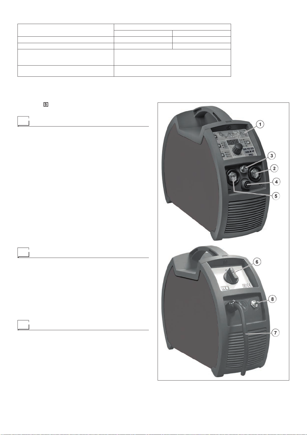
Installation
The installation site for the system must be carefully chosen in or-
der to ensure its satisfactory and safe use. The user is responsi-
ble for the installation and use of the system in accordance with
the producer’s instructions contained in this manual. Before install-
ing the system the user must take into consideration the potential
electromagnetic problems in the work area. In particular, we sug-
gest that you should avoid installing the system close to:
• Signalling, control and telephone cables.
• Radio and television transmitters and receivers.
• Computers and control and measurement instruments.
• Security and protection instruments.
Persons fitted with pace-makers, hearing aids and similar equip-
ment must consult their doctor before going near a welding pow-
er source in operation. The environment in which the equipment
is installed must be suitable for the casing’s protection level. This
system is cooled by means of the forced circulation of air, and
must therefore be placed in such a way that the air may be easily
sucked in and expelled through the apertures made in the frame.
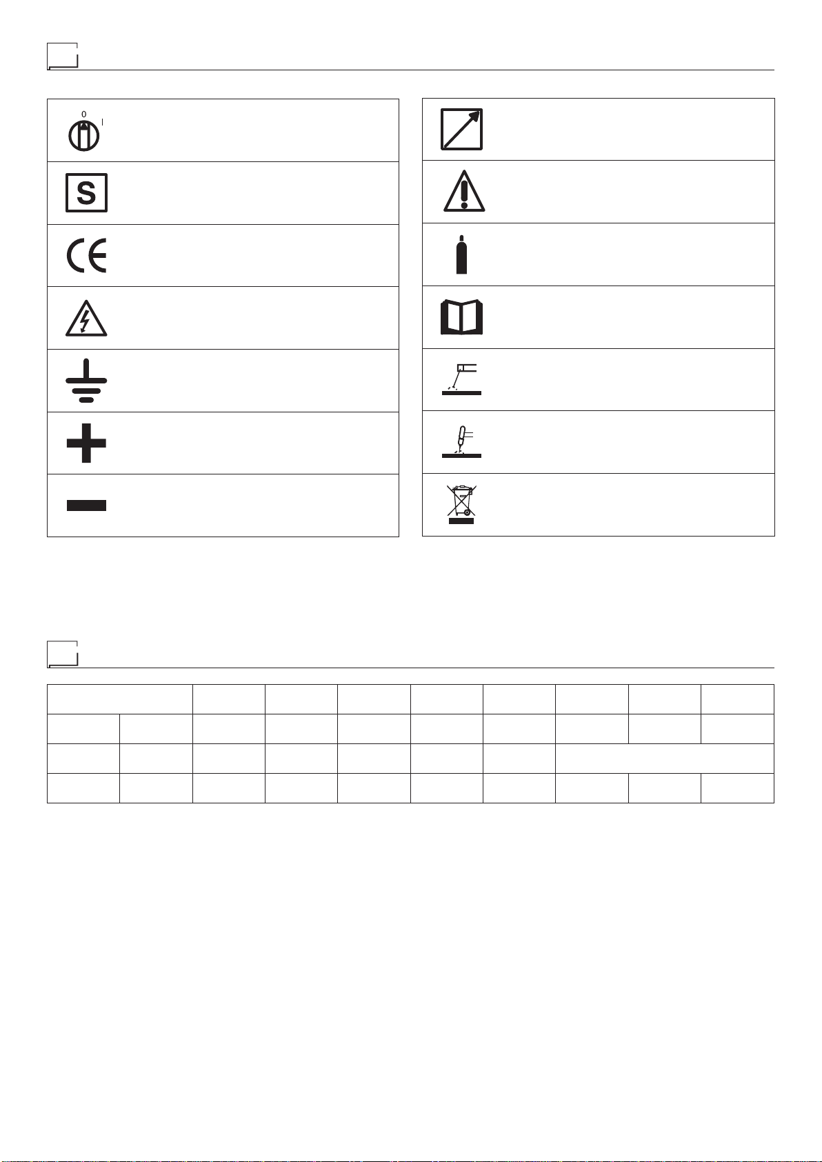
The welding unit is characterised by the following levels:
•
Protection level IP 23 S indicates that the equipment can be used
both indoors and outdoors.
Table 1
Model DIX TIG GO 1406.M HF Pro
TIG DC MMA
Single-phase power supply 50/60 Hz V1~230 ±20%
Mains supply: Zmax (*) Ω0,19
Power input @ I2Max kVA 8,5 9,0
Delayed fuse (I2@ 100%) A20
Power factor / cosφ 0,67 / 0,99
Maximum efficiency degree η0,82 0,84
Open circuit voltage V88
Current range A5÷200 5÷160
Duty cycle @ 100% (40°C) A120 110
Duty cycle @ 60% (40°C) A140 130
Duty cycle @ X% (40°C) A200 (25%) 160 (30%)
Standards IEC60974-1•IEC60974-3•IEC60974-10
Insulation class IP 23 S
Protection class F
Dimensions mm 390-300-135
Weight kg 7,5
(*) Mains supply Zmax: maximum impedance value allowed for the grid according to the EN/IEC 61000-3-11 standard.
WARNING: This equipment does not comply with EN/IEC 61000-3-12. If it is connected to a public low voltage system, it is the responsibility
of the installer or user of the equipment to ensure, by consultation with the distribution network operator if necessary, that the equipment may
be connected.