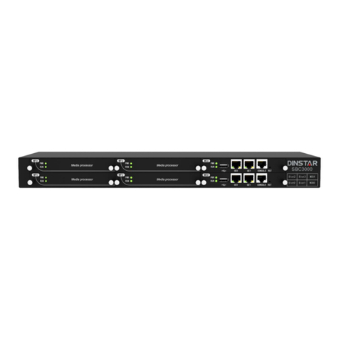
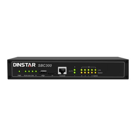
Dinstar SBC1000 User manual

SBC1000 Session Border Controller
User Manual V1.0
Shenzhen Dinstar Co., Ltd.
Address: 9th Floor, Guoxing Building, Changxing Road, Nanshan District, Shenzhen, China
Postal Code: 518052
Telephone: +86 755 61919966
Fax: +86 755 26456659
Emails: sales@dinstar.com, support@dinstar.com
Website: www.dinstar.com

SBC1000 Session Border Controller
Copyright©2011-2018 Dinstar
I
Preface
Welcome
Thanks for choosing SBC1000 Session Border Controller! We hope you will make full use of this rich-feature
device. Contact us if you need any technical support: 86-755-26456110/112.
About This Manual
This manual gives introduction to the SBC1000 device, and provides information about how to install, configure or
use it. Please read the manual carefully before installing it.
Intended Audience
This manual is primarily aimed at the following people:
Users
Engineers who install, configure and maintain SBC1000 device
Revision Record
Document Name
Document Version
Firmware Version
SBC1000 Session Border Controller User Manual
V1.0 (2018/04/04)
1.91.1.5
Conventions
Device mentioned in this document refers to the SBC1000 Session Border Controller. Those words specially noted
in the document are the contents that users need to pay attention to.


SBC1000 Session Border Controller
Copyright©2011-2018 Dinstar
III
Contents
1Production Introduction.........................................................................................................1
1.1 Overview..............................................................................................................................................1
1.2 Application Scenario.............................................................................................................................1
1.3 Product Appearance..............................................................................................................................2
1.4 Desciption of LED Indicators................................................................................................................2
1.5 Functions and Featurres........................................................................................................................3
Key Features................................................................................................................................3
Physical Interfaces.......................................................................................................................3
Capabilities..................................................................................................................................4
VoIP.............................................................................................................................................4
Voice............................................................................................................................................4
Security .......................................................................................................................................5
Call Control.................................................................................................................................5
Maintenance ................................................................................................................................6
Environmental .............................................................................................................................6
2Installation...............................................................................................................................7
2.1 Preparations before Installation.............................................................................................................7
Attentions for Installation.............................................................................................................7
Preparations about Installation Site ..............................................................................................7
Installation Tools..........................................................................................................................8
Unpacking ...................................................................................................................................8
2.2 Installtion of SBC1000 .........................................................................................................................8
Put SBC1000 into Shelf...............................................................................................................8
Connect SBC1000 to Network.....................................................................................................8
How to make RJ45 Network Cable ..............................................................................................9
Connect SBC1000 to Network...................................................................................................10
Troubleshooting about Network Connection ..............................................................................10
3Configurations on Web Interface ........................................................................................11
3.1 How to Log in Web Interface..............................................................................................................11
Preparations for Login ...............................................................................................................11
Log in Web Interface..................................................................................................................12

SBC1000 Session Border Controller
Copyright©2011-2018 Dinstar
IV
3.2 Introduction to Web Interface..............................................................................................................13
3.3 Configuration Flows ...........................................................................................................................14
System Status.............................................................................................................................14
Access Network Status...............................................................................................................16
Access Trunk Status...................................................................................................................17
Core Trunk Status ......................................................................................................................18
Calls Status................................................................................................................................19
Register Status...........................................................................................................................20
Attack List .................................................................................................................................21
3.4 Service................................................................................................................................................22
Media Detection.........................................................................................................................22
CDR ..........................................................................................................................................22
Number Profile ..........................................................................................................................23
Time Profile...............................................................................................................................24
Rate Limit..................................................................................................................................25
Black & White List ....................................................................................................................25
Codec Profile.............................................................................................................................27
Number Manipulation................................................................................................................28
Number Pool..............................................................................................................................29
SIP Header Manipulation.........................................................................................................30
SIP Header Passthrough...........................................................................................................32
Access Network.......................................................................................................................33
Access SIP Trunk.....................................................................................................................37
Core SIP Trunk ........................................................................................................................41
Routing Profile.........................................................................................................................46
3.5 Security ..............................................................................................................................................49
System.......................................................................................................................................49
Access Control...........................................................................................................................50
Security Policy...........................................................................................................................51
3.6 System................................................................................................................................................54
Device Name .............................................................................................................................54
Web Configuration.....................................................................................................................54
Network.....................................................................................................................................55
Port Mapping.............................................................................................................................56
Static Route ...............................................................................................................................57
User Manager ............................................................................................................................58
Date & Time ..............................................................................................................................60
Upgrade.....................................................................................................................................60

SBC1000 Session Border Controller
Copyright©2011-2018 Dinstar
V
Backup & Restore......................................................................................................................61
License ....................................................................................................................................62
Certificate................................................................................................................................62
3.7 Maintenance .......................................................................................................................................62
Login Log..................................................................................................................................62
Operation Log............................................................................................................................63
Security Log ..............................................................................................................................63
Log Management.......................................................................................................................64
Tools..........................................................................................................................................64
4 Abbreviation ........................................................................................................................65

1 Production Introduction
SBC1000 Session Border Controller
Copyright©2011-2018 Dinstar
1
1 Production Introduction
1.1 Overview
With the rapid development of unified communication and All-IP network, more and more enterprises begin to
construct their own IP-based communication system by using IP-PBX and software to improve internal
communication efficiency. However, they need to ensure the NAT traversal for IP multimedia services and the safe
access of users. Dinstar SBC1000 session border controller can help enterprises to solve the abovementioned
problem.
Dinstar SBC1000 provides rich SIP-based services such as safe network access, robust security, system
interconnectivity, flexible session routing & policy management, QoS, media transcoding and media processing for
enterprises. With distributed multi-core processor, hardware structure for non-blocking gigabit switch system as
well as embedded Linux operating system, SBC1000 delivershigh capabilitywhile achieves lowpower dissipation.
It is able to process up to 500 concurrent SIP sessions and transcode 200 concurrent calls. Meanwhile, it allows
encrypted sessions via TLS and SRTP. Apart fromtraditional codecs like G.729, G.723, G.711 and G.726, SBC1000
also supports the transcoding of iLBC,AMR and OPUS.
1.2 Application Scenario
Figure 1-1 Application Scenario of SBC1000

1 Production Introduction
SBC1000 Session Border Controller
Copyright©2011-2018 Dinstar
2
1.3 Product Appearance
Front View:
Back View:
1.4 Desciption of LED Indicators
Indicator
Definition
Status
Description
PWR
Power Indicator
Off
There is no power supply or power
supply is abnormal
On
The device is powered on
RUN
Running Indicator
Slow Flashing(1s)
The device is initialized successfully
and is running normally
Fast flash for two times,
with interval of 1s
Image file is upgraded successfully
Fast Flashing(200ms)
Image file fails to be upgraded
Other Statuses
The device is in abnormal running
GE (0-3 )
/Admin
Link indicator (Green)
Fast Flashing
The network port is connected normally
Off
The network port is not connected, or is
connected abnormally
Speed Indicator (Yellow)
On
Network port works at 1000Mbps
Off
Network port works 10/100Mbps
E1/T1
E1/T1 Status Indicator
Reserved
Reserved
SIM
SIM Card Indicator
Reserved
Reserved

1 Production Introduction
SBC1000 Session Border Controller
Copyright©2011-2018 Dinstar
3
1.5 Functions and Featurres
Key Features
Support up to 5000 SIP registrations
Support 500 concurrent SIP sessions and transcode 200 concurrent sessions
SIP trunks & flexible routing rules for accessing IMS
Media transcoding and fax transcoding (to do)
Embedded VoIP firewall, prevention of DoS and DDos attacks
Bandwidth limitation and dynamic white list & black list
QoS, static route, NAT traversal
Import & export of remote upgrade and configuration data
Encrypted sessions through SRTP and ‘SIP over TLS’
User-friendly web interface, multiple management ways
Support SIP protocols including UDP, TCP and TLS
Support multiple codecs: : G.711A/U,G.723.1,G.729A/B, iLBC,AMR,OPUS
Support multiple softswitches
WebRTC gateway(to do)
Video service(to do)
Physical Interfaces
Ethernet Ports:
4* 10/100/1000M Base-T Ethernet ports (GE0-GE3 for services)
1* 10/100/1000M Base-TAdmin port (for management)
E1/T1 Ports:
2* E1/T1, RJ48C
1* USB 2.0
1* SIM Card Slot
Serial Console
1* RS232, 115200bps, RJ45
LTE Uplink ( to do)

1 Production Introduction
SBC1000 Session Border Controller
Copyright©2011-2018 Dinstar
4
Capabilities
Concurrent Calls
Support 500 SIP sessions at maximum
Transcoding
Supports 200 transcoding calls
CPS for call
25 calls per second at maximum
Registrations
Maximum SIP registrations: 5000
CPS for Registration
25 registrations per second
SIP Trunks
128 SIP trunks at maximum
VoIP
SIP 2.0 compliant, UDP, TCP, TLS,
SIP trunk (Peer to peer)
SIP trunk (Access)
SIP registrations
B2BUA(Back-to-Back User Agent)
SIP Request rate limiting
SIP registration rate limiting
SIP registration scan attack detection
SIP call scan attack detection
SIP anti-attack
SIP Header manipulation
SIP malformed packet protection
Multiple Soft-switches supported
QoS (ToS, DSCP)
NAT Traversal
Voice
Codecs: G.711a/μ,G.723,G.729A/B,iLBC,G.726,AMR,OPUS

1 Production Introduction
SBC1000 Session Border Controller
Copyright©2011-2018 Dinstar
5
RTP Transcoding
Fax: T.38 and Pass-through
No RTP detection
One-way audio detection
RTP/RTCP
RTCP statistics reports
DTMF: RFC2833, SIP Info, INBAND
Silence Suppression
Comfort Noise
Voice Activity Detection (VAD)
Echo Cancellation(G.168, 128ms)
Adaptive Dynamic Buffer
Security
Prevention of DoS and DDos attacks
Control of access policies
Policy-based anti-attacks
Call Security with TLS/SRTP
White List & Black List
Access Rule List
Embedded VoIP Firewall
Call Control
Dynamic load balancing and call routing
Flexible routing engine
Call routing based on prefixes
Call routing based on caller/called number
Regular Expression
Call routing based on time profile
Call routing based on SIP URI
Call routing based on SIP method
Call routing based on endpoint
Caller/called number manipulation

1 Production Introduction
SBC1000 Session Border Controller
Copyright©2011-2018 Dinstar
6
Maintenance
Web-based GUI for Configurations
Configurations Restore/Backup
HTTP Firmware Upgrade
CDR Report and CDR Export
Ping and Tracert
Network Capture
System Logs
Statistics and Reports
Multiple Languages
Centralized Management System
Remote Web and Telnet
Environmental
Redundant Power Supply: 100-240VAC, 50-60 Hz
Power Consumption: 15w
Operating Temperature: 0 ℃~ 45 ℃
Storage Temperature: -20 ℃~80 ℃
Humidity: 10%-90% Non-Condensing
Dimensions (W/D/H): 437×300×44mm (1U)
Unit Weight: 4.5 kg
Compliance: CE, FCC

2 Installation
SBC1000 Session Border Controller
Copyright©2011-2018 Dinstar
7
2 Installation
2.1 Preparations before Installation
Attentions for Installation
Before you install the SBC1000 device, please read the following safety guidelines:
To guarantee SBC1000 works normally and to lengthen the service life of the device, the humidity of the
equipment room where SBC1000 is installed should be maintained at 10%-90% (non-condensing), and temperature
should be 0 ℃~ 45 ℃;
Ensure the equipment room is well-ventilated and clean;
Power supply of SBC1000 should be 100 ~ 240V AC, and its socket is a three-pin socket which should be
grounded well;
It’s suggested that personnel who has experience or who has received related training be responsible for
installing and maintaining SBC1000;
Please wear ESD wrist strap when installing SBC1000;
Please do not hot plug cables;
It’s advised to adopt uninterruptible power supply (UPS).
Preparations about Installation Site
Equipment Cabinet
Ensure the cabinet is well-ventilated and strong enough to bear the weight of SBC1000.
Trunk
Ensure telecom operator has approved to open a trunk.
IP Network
Ensure router under IP network has been prepared, since SBC1000 is connected to the IP network through the
standard 10/100/1000M Ethernet port.
Power Supply
Ensure the socket of SBC1000 is a three-pin socket and power supply is grounded well.

2 Installation
SBC1000 Session Border Controller
Copyright©2011-2018 Dinstar
8
Installation Tools
Screwdriver
ESD wrist strap
Ethernet cables, power wires, telephone wires
Hub, telephone set, fax, and small PBX
Terminal (can be a PC which is equipped with hyperterminal simulation software)
Unpacking
Open the packing container to check whether the SBC1000 device and all accessories have been in it:
One SBC1000 device
One 1.8-meter-long of power wire (AC 250V/4A)
Two network cables
One grounding cable
One serial console cable
Flanks and screws
2.2 Installtion of SBC1000
Put SBC1000 into Shelf
Put the SBC1000 device on the shelf or cabinet horizontally;
Connect SBC1000 to Network
SBC1000 has five network ports, namely the gigabit network port for services (from GE0 to GE3) and the gigabit
network port for network management (Admin). It is advised to connect GE0, GE1, GE2 or GE3 to the IP
network.
Both GE0/GE1/GE2/GE3 and Admin can be used to carry out management on SBC1000, but generally
GE0/GE1/GE2/GE3 are put in use. Admin is used when there is a need to separate management-related processing
from service processing on SBC1000.

2 Installation
SBC1000 Session Border Controller
Copyright©2011-2018 Dinstar
9
How to make RJ45 Network Cable
Step1. Prepare a twisted-pair cable with a length of at least 0.6 meters, and then remove the shuck of the network
cable;
Step2. Sequence the wires of the cable according to EIA/TIA 568B Standard (as shown in the following figure);
Wire sequence of 568B: white & orange, orange, white & green, blue, white & blue, green, white & brown, brown.
Step3. Put the wires into the PINs of a RJ45 joint according to the abovementioned wire sequence of EIA/TIA
568B, and then use a wire crimper to crimp the RJ45 joint.
Step4. On the other end of the network cable, sequence the wires of the cable according to EIA/TIA 568A
Standard (as shown in the following figure);
Wire sequence of 568A: white & green, green, white & orange, blue, white & blue, orange, white & brown, brown.
Step5. Put the wires into the PINs of a RJ45 joint according to the abovementioned wire sequence of EIA/TIA
568A, and then use a wire crimper to crimp the RJ45 joint.
Step6.Test the usability of the network cable.

2 Installation
SBC1000 Session Border Controller
Copyright©2011-2018 Dinstar
10
Connect SBC1000 to Network
SBC1000 has five network ports, namely the gigabit network ports for services (from GE0 to GE3) and the gigabit
network port for management (Admin). It is advised to connect GE0/GE1/GE2/GE3 to the IP network.
Both GE0/GE1/GE2/GE3 and Admin can be used to carry out management on SBC1000, but only
GE0/GE1/GE2/GE3 is put in use generally. Admin is used when there is a need to separate management processing
from service processing on SBC1000.
Troubleshooting about Network Connection
When the SBC1000 device has been connected to gigabit Ethernet, but the SPEEDand LINK indicatorson the front
panel of the device are still dull, it can be concluded that network connection fails.
You can try to find the reasons for network connection failure according to the following steps.
Step1: In case that the network cable is inserted into one of the service ports, please pull out the network cable and
insert it into the ‘Admin’ port. If the indicator for the ‘Admin’port is on, it can be concluded that the corresponding
service port is faulty.
In case that the network cable is inserted into the ‘Admin’ port, please pull out the network cable and insert it into
one of the service ports. If the indicator for the corresponding service port is on, it can be concluded that the ‘Admin’
port is faulty.
Step2: If the corresponding indicator is still dull after the network cable is inserted into other network port, please
connect the network cable to a laptop or a PC, and then go to visit a website.
Step3: If the laptop or PC can visit a website normally, it can be concluded that the network cable is usable but the
network port of SBC1000 is faulty.
Step4: If the laptop or PC cannot visit a website, it can be concluded that the network cable is unavailable.

3 Configurations on Web Interface
SBC1000 Session Border Controller
Copyright©2011-2018 Dinstar
11
3 Configurations on Web Interface
3.1 How to Log in Web Interface
Preparations for Login
SBC1000 has five network ports, namely the gigabit network ports for services (from GE0 to GE3) and the gigabit
network port for management (Admin). It is advised to connect GE0/GE1/GE2/GE3 to the IP network.
The default IPaddress of the ‘Admin’ port is 192.168.11.1, while those of GE0, GE1, GE2 and GE3 are 192.168.12.1,
192.168.13.1, 192.168.14.1 and 192.168.15.1 respectively.
First Use
At the first time that the SBC1000 device is put in use, please connect the device’s Admin port to a PC by using a
network cable, and then modify the IP address of the PC to make it at the same network segment with of the default
IP address of the Admin port. The format of PC IP address is 192.168.11.XXX, since the default IP of Admin port
is 192.168.11.1
Daily Use
Connect the service port (GE0/GE1/GE2/GE3) of SBC1000 to a 1000Mbps or 10/100mbps switch.
If SBC1000 is connected to a 1000Mbps switch, the link indicators on the front panel turn green and flash, while
the speed indicators turn yellow.
If SBC1000 is connected to a 10/100Mbps switch, the link indicators on the front panel turn green and flash, while
the speed indicators remain dull.
SBC1000
Switch
PC
Internet

3 Configurations on Web Interface
SBC1000 Session Border Controller
Copyright©2011-2018 Dinstar
12
Note:
At the first time that the SBC1000 device is used, only the Admin port is allowed to visit the Web interface (other
networkports are disabled). If you want to connect the SBC1000 device through other network ports, please connect
the Admin port to a PC and log into the Web interface of the device, and then enable GE0, GE1, GE2 and GE3 ports
on the SecurityAccess Control page.
Log in Web Interface
Open a web browser and enter the IP address of the Admin port of SBC1000 (https:// 192.168.11.1). Then input
username, password and verification code on the displayed login GUI. The default username is admin, while the
default password is admin@123#.
Figure 3-1 Login GUI
For security consideration, it is suggested that you should modify the username and password on the System
Users page.
Figure 3-2 Modify Password

3 Configurations on Web Interface
SBC1000 Session Border Controller
Copyright©2011-2018 Dinstar
13
Note:
If you forget the IP address after modification and cannot log in the Web interface, please use a serial cable to
connect the Console port of SBC1000 with a PC. Enter the ‘en’ mode and input ‘show interface’ to query the IP
address.
3.2 Introduction to Web Interface
The Web Interface of the SBC1000 consists of the main menu bar, navigation tree and detailed configuration
interfaces. Click a button of the main menu bar and select a node of the navigation tree on the left, you will see a
detailed display interface or configuration interface:
Figure 3-3 Structure of Web Interface
Table 3-1 Introduction to Web Interface
Index
Item
Description
1
Main Menu Bar
The main menu bar of SBC1000, including buttons of Overview, Service,
Security, System and Maintenance
2
Navigation Tree
The navigation tree of each button of the main menu bar
3
Detailed Interface
The detailed configuration interface or display interface of a node under
navigation tree
4
Language
Choose Chinese or English
5
Logout
Click logout, and you will exit the Web interface

3 Configurations on Web Interface
SBC1000 Session Border Controller
Copyright©2011-2018 Dinstar
14
6
To add configurations
7
To edit/modify configurations
8
To delete configurations
3.3 Configuration Flows
The following is the general configuration flows of SBC1000:
Figure 3-4 Configuration Flow
System Status
Log into the Web interface, and the ‘System Status’ page is displayed. On the page, call statistics and its graphic,
device information, MCU(Main Control Unit) status as well as general information are shown.
Log in Web Interface
Configure IP Address of
GE0/GE1/GE2/GE3
Configure Service Items
Configure Security
Strategies
Upload Certificates
Configure from top
to buttom based
on navigation tree
Complete Other
Configurations
Such as time,
user management
and static routes
Table of contents
Other Dinstar Controllers manuals
