DINUY IT KNX 001 User manual

EGB
INTERRUPTOR 1 CANAL INALÁMBRICO
ESPECIFICACIONES TÉCNICAS
Tensión Alimentación 230V~ 50Hz
Consumo Propio 35mA
Radio-Frecuencia Emisión codificada en 868,4MHz
con PRA>8mW y una penetración
de 100m (campo abierto)
Compatible con KNX-RF: CH_Light_Actuator_Scene (0103h)
ProtecciónAmbiental IP20
Tª Funcionamiento -10ºC ~ +45ºC
Dimensiones 1 módulo de anchura (17,5mm)
DESCRIPCIÓN
Se trata de un actuador RF-KNX que emula el funcionamiento del canal (chanel code)
CH_Light_Actuator_Scene 0x103.
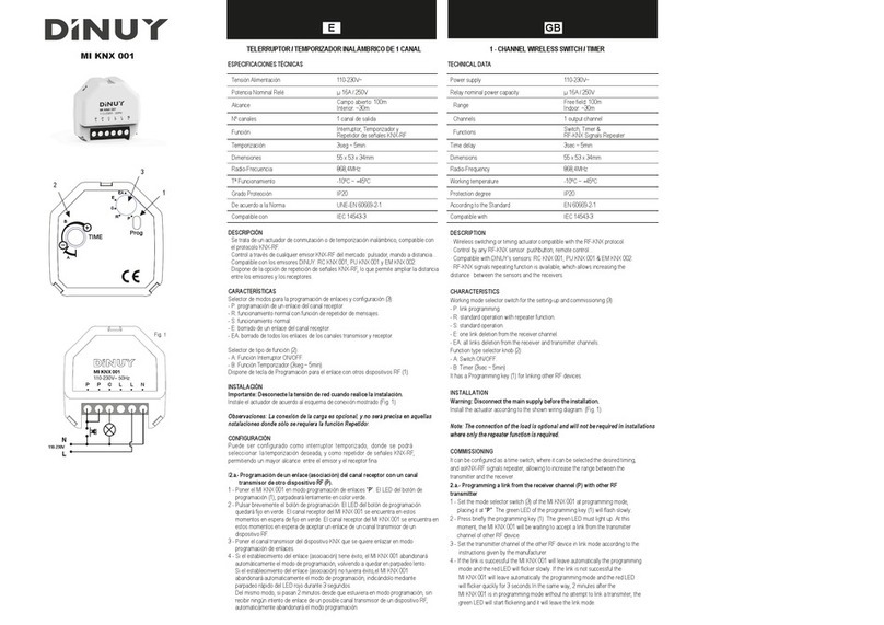
Se compone de: LED indicador (A), Selector de Tiempo (B), Pulsador de Configuración (C) y
Selector de Modos (D).
CARACTERÍSTICAS
Selector de modos para la programación de enlaces y configuración:
- B: borrado de un enlace del canal receptor.
- P: programación de un enlace del canal receptor o del canal transmisor.
- F: funcionamiento normal.
- A: funcionamiento normal con función de repetidor.
- R: borrado de todos los enlaces de los canales trnasmisor y receptor.
Funcionamiento como telerruptor o interruptor temporizado.
Posibilidad de activar la función repetidor.
Posibilidad de conectar un pulsador auxiliar para:
- Control local de la carga del mecanismo.
- Control remoto via RF de otro u otros mecanismos receptores RF asociados.
Compatible con protocolo KNX ISO-IEC 14543-2. incorporando dos objetos:
- El pulsador auxiliar responde al objeto CH_PB_Toggle 0x02.
- El actuador responde al objeto CH_Light_Actuator_Scene 0x103.
INSTALACIÓN
Instale el actuador de acuerdo al esquema de conexión mostrado.
La conexión del pulsador auxiliar (E) es opcional. Dependerá su instalación de si se requiere de
un pulsador de control local de la carga conectada al Interruptor de RF ó de si se requiere el
control remoto vía RF de otro u otros mecanismos receptores RF asociados.
FUNCIONAMIENTO
A.- Funcionamiento a través de su pulsador auxiliar (E)
El funcionamiento del IT KNX 001 desde un pulsador externo es el siguiente:
Cualquier pulsación corta (<300mseg) del pulsador auxiliar tiene como consecuencia:
- Un cambio, ON u OFF del estado anterior en que se encontraba la carga local conectada.
- El envío, vía radio, de un mensaje de ON u OFF, en concordancia con el cambio de estado
que realiza la carga local.
Los tipos de comandos enviados son compatibles con el objeto “CH_PB_Toggle 0x02” (0002h).
B.- Funcionamiento a través de su canal receptor RF
La carga conectada al IT KNX 001 puede gobernarse remotamente, vía radio, desde un
dispositivo transmisor RF programado.
Los tipos de comandos aceptados son compatibles con el objeto RF-KNX
CH_Light_Actuator_Scene 0x103.
IT KNX 001
Montaje Raíl DIN
Capacidad de Corte 16A 250V cos
j
=1
Temporización 3segundos ~ 10min
WIRELESS 1-CHANNEL SWITCH
TECHNICAL DATA
Power supply 230V~ 50Hz
Consumption 35mA
Radio-Frequency Codified transmission in 868,4MHz
with ERP>8mW and a coverage of
100m (in the free field)
Compatible with RF-KNX: CH_Light_Actuator_Scene (0103h)
Protection degree IP20
Working temperature -10ºC ~ +45ºC
Dimensions 1 module wide (17,5mm)
DESCRIPCIÓN
It is based on a RF-KNX actuator which emulates the working mode of the channel code
CH_Light_Actuator_Scene 0x103.
It is composed by: LED (A), Time Selector (B), Commissioning Pushbutton (C) and
Working Mode Selector Switch (D).
CHARACTERISTICS
Working mode selector switch for the setting-up and commissioning:
- B: delete a link from the receiver channel.
- P: link programming of the transmitter or receiver channel.
- F: normal operation.
- A: normal operation with repeater function.
- R: delete all links from the transmitter and receiver channels.
Operation as impulse relay or time switch.
Possibility of working as RF signals repeater.
Possibility of wiring an additional wired pushbutton to:
- Local control of the load connected to the device.
- Remote control, via RF, of one or several linked receivers.
Compatible with ISO-IEC 14543-2 KNX protocol. Two objects:
- The auxiliary pushbutton answers to the object CH_PB_Toggle 0x02.
- The actuator answers to the object CH_Light_Actuator_Scene 0x103.
INSTALLATION
Install the actuator according to the wiring diagram.
The auxiliary pushbutton (E) is optional. It depends on if the installation requires a local control for
the load connected to the IT KNX 001 or if it is necessary to control remotely other linked RF-KNX
devices.
WORKING MODES
A.- Operation with the external Pushbutton (E)
Any short press (<300msec) of the pushbutton has as the effect of:
- The change of the previous state of the load connected to the IT KNX 001: ON or OFF.
- The transmission of an ON or OFF message, in concordance with the change of the load. The
messages are compatible with the RF-KNX object ‘CH_PB_Toggle 0x02’ (0002h).
B.- Operation through its receiver channel
The load connected to the IT KNX 001 can be controlled remotely with a RF transmitter.
The accepted messages are compatible with the RF-KNX object ‘CH_Light_Actuator_Scene’
0x103.
Mounting DIN-rail
Breaking capacity 16A 250V cos
j
=1
Time delay 3sec ~ 10min
min
AC
B
D
INT
3s
13
5
10
min
R
PF
A
B
IT KNX 001
E
N
L

GB E
DINUY S.A.
c/Auzolan Nº2
20303 Irún (Spain)
info@dinuy.com
www.dinuy.com
CONFIGURACIÓN
A.- Programación de un enlace del canal receptor
Para realizar un enlace (asociación) del canal receptor del IT KNX 001 con un canal transmisor
de un dispositivo KNX-RF (tecla, mando, detector de movimiento,… ):
1.- Poner el selector de modos del IT KNX 001 en modo programación de enlace, colocándolo
en la posición “P”. El LED rojo parpadeará lentamente.
2.- Con la ayuda de un clip, presionar el pulsador de configuración (C) hasta que el LED
parpadee rápidamente. El canal receptor del IT KNX 001 se encuentra en estos momentos
en espera de aceptar un enlace de un canal transmisor de un dispositivo RF
3.- Poner el canal transmisor del dispositivo RF que queremos enlazar en modo programación
de enlaces, de acuerdo a las instrucciones del fabricante.
4.- Si el establecimiento del enlace tiene éxito, el LED verde se encendenrá durante 5 seg.,
para después pasar a modo de reposo, parpadeando en rojo lentamente. Si el
establecimiento del enlace no tuviera éxito, el LED rojo se mantendrá encendido 5 seg.
al cabo de los cuales pasara a modo de reposo, parpadeando en rojo lentamente.
Del mismo modo, si pasa 1 minuto desde que el IT KNX 001 estuviera en modo
programación sin recibir ningún intento de enlace de un posible canal transmisor de un
dispositivo RF, , el LED rojo se mantendrá encendido 5 seg. después abandonará el
modo programación, quedando el LED rojo parpadeando lentamente.
5.- Para que el IT KNX 001 vuelva a ser operativo, situar el selector en la posición F” o “A”.
B.- Programación de un enlace del canal transmisor
Para realizar un enlace (asociación) del canal transmisor del IT KNX 001 con un canal receptor
de un dispositivo KNX-RF:
1.- Poner el receptor que queremos enlazar en modo programación de enlaces.
2.- Acontinuación, poner el ITKNX 001 en modo programación de enlaces, colocando el
selector de modo sobre “P”. El LED rojo parpadeará lentamente.
3.- Pulsar con un clip o similar, sobre el pulsador de configuración. El LED rojo parpadeará
rápidamente.
4.- Si el establecimiento del enlace tiene éxito, el LED verde se encendenrá durante 5 seg.,
para después pasar a modo de reposo, parpadeando en rojo lentamente. Si el
establecimiento del enlace no tuviera éxito, el LED rojo se mantendrá encendido 5 seg.
al cabo de los cuales pasara a modo de reposo, parpadeando en rojo lentamente.
C.- Borrado de un enlace del canal receptor
Para borrar un enlace del canal receptor del IT KNX 001 con un canal transmisor de un
dispositivo RF (sensor de Tª, sensor apertura ventanas, detector de presencia...):
1.- Poner el selector de modos del IT KNX 001 en modo borrado de enlace, colocándolo en la
posición “B”. El LED de color rojo se enciende permanente.
2.- Con la ayuda de un clip, presionar el pulsador (A) hasta que el led de color rojo parpadee
rápidamente. El canal receptor del IT KNX 001 se encuentra en estos momentos en espera
de aceptar un enlace de un canal transmisor de un dispositivo RF.
3.- Poner el canal transmisor del dispositivo RF que queremos borrar en modo programación de
enlaces.
4.- Si el borrado del enlace tiene éxito, el LED verde se encendenrá durante 5 seg.,
para después pasar a modo de reposo, parpadeando en rojo lentamente. Si el
borrado del enlace no tuviera éxito, el LED rojo se mantendrá encendido 5 seg.
al cabo de los cuales pasara a modo de reposo, parpadeando en rojo lentamente.
Del mismo modo, si pasa 1 minuto desde que el IT KNX 001 estuviera en modo
borrado sin recibir ningún intento de un posible canal transmisor de un dispositivo RF,
el LED rojo se mantendrá encendido 5 seg. después abandonará el modo programación,
quedando el LED rojo parpadeando lentamente.
5.- Para que el IT KNX 001 vuelva a ser operativo, situar el selector en la posición “F o “A”.
D.- RESET: Borrado de todos los enlaces del canal receptor y del canal transmisor
Para borrar todos los enlaces del IT KNX 001:
1.- Poner el IT KNX 001 en modo RESET, colocando el selector de modo sobre “R”. El LED
parpadeará lentamente.
2.- Pulsar con un clip o similar, sobre el pulsador de configuración. El LED quedará encendido
de forma permanente.
3.- Seguir pulsando hasta que el LED vuelva a parpadear lentamente.
4.- Para que el IT KNX 001 vuelva a ser operativo, situar el selector de modo sobre “F” o “A”.
E.- Modo Repetidor
El IT KNX 001 puede, opcionalmente, realizar la función de repetidor de telegramas RF.
Esta función es útil solo en aquellas instalaciones donde se detecten problemas de comunicación
entre dispositivos RF debido a la distancia. En estos casos, un dispositivo situado entre ambos,
capaz de realizar la función repetidor (retransmisión), se convierte en una herramienta útil para
solventar este problema.
No se recomienda la utilización de más de tres repetidores en una instalación.
La función repetidor se activa colocando el selector de modo en la posición A. El resto
de la funcionalidad del interruptor de RF permanece sin alteración.
COMMISSIONING
A.- Programming a link of the receiver channel
To link the receiver channel of the IT KNX 001 with the sender channel of other RF-KNX device
(pushbutton, touch control, motion detector,...):
1.- Set the mode selector switch (D) at ‘P’ position. The LED (A) will flicker slowly.
2.- Press the configuration pushbutton (C) with help of a clip or something similar.The LED will
flicker quickly. The receiver channel of the IT KNX 001 is now waiting to accept a link from the
transmitter channel of the other RF-KNX device.
3.- Set the transmitter channel of the other RF-KNX device in ‘link programming mode’ according
to the instructions given by the manufacturer.
4.- If the link is successful the LED of the IT KNX 001 will be off for 5 seconds and then it will
flicker slowly again. If the link is not successful the IT KNX 001 will leave automatically the
programming mode and the LED will flicker slowly. In the same way, 2 minutes after the
IT KNX 001 is in programming mode without no attempt to link a sender channel from other
device it will leave this mode automatically and the LED will flicker slowly.
5.- To become the IT KNX 001 operational would be necessary to set the mode selector switch
at ‘F’ or ‘A’ position.
B.- Programming a link of the transmitter channel
To link the transmitter channel of the IT KNX 001 with the receiver channel of other RF-KNX
device:
1.- Set the receiver in link mode.
2.- Set the mode selector switch of the IT KNX 001 at ‘P’ position.The LED will flicker slowly.
3.- Press the configuration pushbutton with help of a clip or something similar.The LED will
flicker slowly.
4.- If the link is successful the LED of the IT KNX 001 will be off for 5 seconds and then it will
flicker slowly again. If the link is not successful the IT KNX 001 will leave automatically the
programming mode and the LED will flicker slowly.
C.- Delete a link from the receiver channel
To delete a link with other RF transmitter from the receiver channel of the IT KNX 001:
1.- Set the mode selector switch at ‘B’ position. The LED will be permanently on.
2.- Press the configuration key with help of a clip. The LED will flicker quickly. The receiver
channel of IT KNX 001 is waiting to receive the signal from the sender channel
of the other device we want to unlink.
3.- Set the sender channel of the device we want to unlink in programming mode according to
the instructions given by the manufacturer.
4.- If the unlink is successful the LED will be off for 5 seconds and then will be on permanently.
If the unlink is not successful the IT KNX 001 will leave automatically the programing mode
and the LED will be on constantly. In the same way, 2 minutes after the IT KNX 001 is in
programming mode without no attempt to unlink a sender channel from other device it will
leave this mode automatically and the LED will be on constantly.
5.- To become the IT KNX 001 operational set the mode selector switch at ‘F’or ‘A’ position.
D.- RESET: Delete all links from the receiver and sender channel
To delete all links from the IT KNX 001:
1.- Set the mode selector switch in RESET (’R’). The LED will flicker slowly.
2.- Press the configuration pushbutton with a clip. The LED will be on constantly.
3.- Keep on pressing until the LED flickers slowly.
4.- To become the IT KNX 001 operational set the mode selector switch over ‘F’or ‘R’.
E.- Repeater mode
The IT KNX 001 can also act as a signal repeater.
This function is useful in the installations where are problems with the coverage between the
devices because of the distance.
It is not advisable to use more than three repeaters in the same installation.
This function is activated setting the mode selector switch in ‘A’. The rest of functionality continues
without changes.
21 3
IT KNX 001
PF
A
R
B
min
INT
2
46
8
10
IT KNX 001
PF
A
R
B
min
INT
2
46
8
10
4
IT KNX 001
PF
A
R
B
min
INT
2
46
8
10
5
IT KNX 001
PF
A
R
B
min
INT
2
46
8
10
1 2
IT KNX 001
PF
A
R
B
min
INT
2
46
8
10
3
IT KNX 001
PF
A
R
B
min
INT
2
46
8
10
4
IT KNX 001
PF
A
R
B
min
INT
2
46
8
10
2 3
IT KNX 001
PF
A
R
B
min
INT
2
46
8
10
4
IT KNX 001
PF
A
R
B
min
INT
2
46
8
10
5
IT KNX 001
PF
A
R
B
min
INT
2
46
8
10
1
IT KNX 001
PF
A
R
B
min
INT
2
46
8
10
2
IT KNX 001
PF
A
R
B
min
INT
2
46
8
10
3
IT KNX 001
PF
A
R
B
min
INT
2
46
8
10
4
IT KNX 001
PF
A
R
B
min
INT
2
46
8
10
1
IT KNX 001
PF
A
R
B
min
INT
2
46
8
10
Other DINUY Switch manuals
Popular Switch manuals by other brands
Hama
Hama Standby off switch Operating instruction
Netgate
Netgate Nighthawk S8000 user manual
Sunricher
Sunricher SR-ZV9100A-A manual
3Com
3Com 2126-G - Baseline Switch user guide
Optical Systems Design
Optical Systems Design OSD2251EP Series Operator's manual
EtherWAN
EtherWAN EX32908 series quick start guide
